HAL Id: hal-00979607
https://hal.archives-ouvertes.fr/hal-00979607
Submitted on 16 Apr 2014
HAL is a multi-disciplinary open access
archive for the deposit and dissemination of
sci-entific research documents, whether they are
pub-lished or not. The documents may come from
teaching and research institutions in France or
abroad, or from public or private research centers.
L’archive ouverte pluridisciplinaire HAL, est
destinée au dépôt et à la diffusion de documents
scientifiques de niveau recherche, publiés ou non,
émanant des établissements d’enseignement et de
recherche français ou étrangers, des laboratoires
publics ou privés.
Phase-Shifting Cell for Dual Linearly Polarized
Reflectarrays With Reconfigurable Potentialities
Tony Makdissy, Raphaël Gillard, Erwan Fourn, Etienne Girard, Hervé Legay
To cite this version:
Tony Makdissy, Raphaël Gillard, Erwan Fourn, Etienne Girard, Hervé Legay. Phase-Shifting Cell
for Dual Linearly Polarized Reflectarrays With Reconfigurable Potentialities. IEEE Antennas and
Wireless Propagation Letters, Institute of Electrical and Electronics Engineers, 2013, 13, pp.11-14.
�10.1109/LAWP.2013.2294873�. �hal-00979607�
Abstract—This letter presents a new phase-shifting cell
topology for dual-linearly polarized reflectarrays. It consists of two orthogonal sets of straight slots etched in a metallic plane and loaded with four capacitances in order to control the phase of the reflected wave. Measurements have demonstrated that the convenient capacitive loading of the central slots permits to provide 331° of phase range at 12.5GHz with linear and parallel dispersions for the different phase states.
Index Terms—Dual linear polarization, phase-shifting cell,
reflectarray antennas.
I. INTRODUCTION
HE unit cell of microstrip printed reflectarrays usually uses patches or slots to vary the phase of the reflected wave. For passive structures, modifying the dimensions of the patch [1], the length of the slot [2] or the stub [3] permits to change the resonant frequency and so the reflected phase. Several resonators are generally combined, on a single layer [4] or a multilayer [5] substrate(s), to increase the phase range. However single layer solutions are preferable as they result in a simpler technological process. For reconfigurable reflectarrays, the reflected phase has to be controlled dynamically over 360° with a reduced number of reconfigurable elements loading the unit cell. This reduced number permits to preserve a low cost antenna. Different kind of elements can be used to provide this reconfigurability such as PIN diodes [6], varicap diodes [7] and MEMS switches [8].
In this letter, we propose a new dual-polarization phase-shifting cell combining several resonators and using a reduced number of capacitances to tune the phase. It is an evolution of the C-band cell we studied in [9]. Here, a further step towards a future reconfigurable cell in Ku-band is presented. Although the cell is still passive, an improved design is proposed relying on a technological process fully compatible with MEMS implementation. It also takes benefit of the required dielectric assembly to add a supplementary vertical slot in order to improve the linearity of the phase response without increasing cell size. A study of the effect of incidence angle is also given.
Manuscript received October 10, 2013, revised November 14, 2013, accepted December 6, 2013. This study has been carried out within the ESA MERCURY project (22620/09/NL/JD). Authors would like to thank the LAAS for the realization of the cells.
T. Makdissy, R. Gillard and E. Fourn are with the Institute of Electronics and Telecommunications of Rennes, European University of Brittany, INSA, UMR CNRS 6164, 35708 Rennes (e-mail: tony.makdissy@insa-rennes.fr).
E. Girard and H. Legay are with the Research and Development Department, Thales Alenia Space, 31037 Toulouse, France.
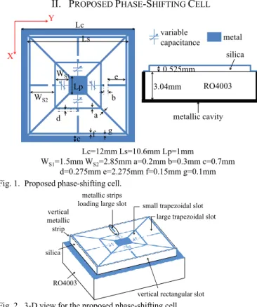
II. PROPOSED PHASE-SHIFTING CELL
Fig. 1. Proposed phase-shifting cell.
Fig. 2. 3-D view for the proposed phase-shifting cell.
The proposed phase-shifting cell (Fig. 1) is designed using a technological process that is fully compatible with the fabrication of MEMS capacitive elements. It is thus a preliminary step towards a future reconfigurable cell. The cell is printed on a chip of fused silica of relative permittivity 3.78 and of thickness 0.525mm placed on a 3.04mm thick RO4003 substrate of relative permittivity 3.55. It consists of two orthogonal sets of trapezoidal slots. Each of the smallest slots in the centre of the cell is loaded with just one capacitance. Modifying the value of this capacitance permits to modulate the electric length of the corresponding slot and to control the phase of the reflected wave. Six slots are combined for each polarization in order to enhance the bandwidth. The longest slots, rectangular ones, are located on the vertical edges of the chip of silica (Fig. 2). The resonant frequency of the largest trapezoidal slot was optimized by adjusting the dimensions of the metallic strips loading this slot. The x-oriented slots are used for y-polarization and vice versa. The connection between the metallization on silica and the metallization on RO4003 is provided using vertical metallic strips in the four corners of the chip (Fig. 2).
X Y Lc Ls WS1 WS2 Lp d c f g a b e 0.525mm 3.04mm RO4003 silica metallic cavity metal variable capacitance Lc=12mm Ls=10.6mm Lp=1mm WS1=1.5mm WS2=2.85mm a=0.2mm b=0.3mm c=0.7mm d=0.275mm e=2.275mm f=0.15mm g=0.1mm silica RO4003 vertical metallic strip
small trapezoidal slot large trapezoidal slot
vertical rectangular slot metallic strips
loading large slot
Phase-Shifting Cell for Dual Linearly Polarized
Reflectarrays with Reconfigurable Potentialities
Tony Makdissy, Raphaël Gillard, Erwan Fourn, Etienne Girard and Hervé Legay
III. INITIAL CELL PERFORMANCES
The performances of the proposed topology have been assessed at 12.5GHz with periodic (master/slave) boundary conditions and Floquet port for the excitation, using HFSS® electromagnetic simulator.
When the loads of the central slots evolve from an open-circuit to a short-open-circuit through interdigital capacitances for the intermediate states (Fig. 3), the phase range provided at the central frequency is 326° (Fig. 4). As a possible application, 8 different phase states with a uniform 45° separation could be produced. The maximum difference in frequency dispersion between two phase states is 54°/GHz at 12.5GHz which reflects the parallelism between the phase responses. Moreover, losses are less than 1dB above 11.7GHz (Fig. 4). The dimensions (in µm) of each interdigital capacitance are summarized in Table I. Table II shows the values of the ideal capacitances (lumped elements in HFSS simulations) providing the same phase responses as the used interdigital capacitances.
TABLEI
DIMENSIONS OF THE CAPACITANCE (µm) FOR THE INTERMEDIATE STATES
State L α β σ ai bi ae be 2 870 0 40 30 120 120 95 120 3 1190 0 40 30 120 120 95 120 4 1080 0 20 20 130 130 80 130 5 1600 20 40 30 120 120 120 120 6 1440 0 20 20 130 130 110 130 7 1860 0 20 20 130 130 170 130 TABLEII
VALUES OF THE IDEAL CAPACITANCES PROVIDING THE SAME PHASE
RESPONSES AS THE INTERDIGITAL CAPACITANCES
State 2 3 4 5 6 7
C (fF) 50 64 73 83 95 120
Fig. 3. Open-circuit, interdigital capacitance and short-circuit loading the central slots.
Fig. 4. Simulated reflected phase and losses for x-polarization when the capacitances loading the oriented central slots change (for any state of the y-polarization).
Furthermore, both polarizations are independent; indeed, when the capacitances loading the y-oriented central slots are modified and the capacitances loading the x-oriented central slots are maintained fixed, the reflected phase and losses of y-polarization are not modified (Fig. 5). Note that similar results are obtained for all the possible states in y-polarization.
Fig. 5. Superimposed curves (simulations) for the reflected phase and for losses in y-polarization when the y-oriented central slots are loaded with variable capacitances (C varying from open-circuit to short-circuit) and the x-oriented central slots are loaded with fixed capacitances (C of “State 3”).
The longest slots, rectangular ones, located on the vertical edges of the chip of silica are essential for the good functioning of the cell. They permit to provide a good parallelism between the different phase responses, over a large bandwidth, without increasing cell size. In order to demonstrate their contribution to the linearity and parallelism of the curves, an additional simulation has been achieved where these vertical slots are short-circuited (Fig. 6). A comparison with Fig. 4 clearly shows that the bandwidth is now severely reduced with a sharp resonance at higher frequencies.
Fig. 6. Simulated reflected phase and losses for x-polarization when the slots on the vertical edges of the chip of silica are short-circuited.
IV. CELL PERFORMANCES UNDER INCIDENCE
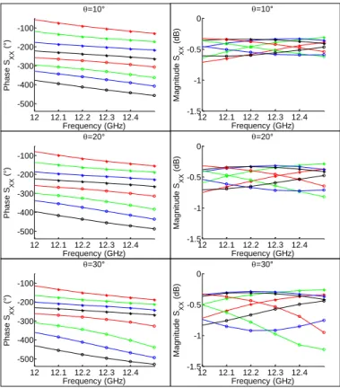
A unit cell must operate over a range of angle of incidence representative of the real illumination conditions of the array. To do so, the cell is now placed in an infinite periodic array. It is illuminated with a plane wave under oblique incidence (Fig. 7). In this section, just the TM polarization (E plane) is presented as the TE polarization (H plane) will be treated in the next section where the cell is simulated inside a metallic waveguide. For the TM polarization (E plane), parasitic resonances appear, even for a slight angle of incidence θ=10°, as it is shown in Fig. 8 for state 4. These resonances appear at frequencies higher than 12.5GHz and lower than 12GHz.
Fig. 9 illustrates the phase responses and losses of the cell for the TM polarization (E plane), for all states, with incidence angle up to 30°, in the reduced bandwidth (12-12.5GHz). The provided phase range is around 320° regardless the angle of incidence. When the incidence angle is increased, losses L ai bi a e be σ β α
State 1: open-circuit capacitanceinterdigital State 8: short-circuit 0.2mm 0.15mm baee 11.5 12 12.5 13 13.5 -500 -400 -300 -200 -100 0 Frequency (GHz) Phas e SX X (° ) 11.5 12 12.5 13 13.5 -1.5 -1 -0.5 0 Frequency (GHz) M agnit ude SX X (dB) State 1 : open-circuit State 2 State 3 State 4 State 5 State 6 State7 State 8 : short-circuit 11.50 12 12.5 13 13.5 100 200 300 Frequency (GHz) Phas e SY Y (° ) 11.5 12 12.5 13 13.5 -1.5 -1 -0.5 0 Frequency (GHz) M agnit ude SY Y (dB) State 1 : open-circuit State 2 State 3 State 4 State 5 State 6 State7 State 8 : short-circuit 11.5 12 12.5 13 13.5 -500 -400 -300 -200 -100 0 Frequency (GHz) P h a s e S X X ( °) 11.5 12 12.5 13 13.5 -10 -8 -6 -4 -2 0 Frequency (GHz) M a g n itu d e S X X ( d B )
become higher and the different phase responses of the cell are slightly shifted toward lower frequencies. However, for incidence angle up to 20°, losses are less than 1dB all over the band (4%), and the different phase responses are maintained parallel.
Fig. 7. Proposed phase-shifting cell under oblique incidence (considering x-polarization).
Fig. 8. Losses of “State 4” for the TM polarization (E plane) for different incidence angles (for any state of the y-polarization).
Fig. 9. Phase responses and losses of the cell for the TM polarization (E plane) in a reduced frequency band for different incidence angles (for any state of the y-polarization).
An additional simulation, for a particular incidence angle (θ=20°, φ=30°) when the cell is loaded with the same capacitances in both polarizations, shows that the magnitude of the cross-polarization reflection is maintained below -25dB over the bandwidth 12-12.5GHz (Fig. 10) which demonstrates the isolation between both polarizations.
Fig. 10. Simulated magnitude of the cross-polarization reflection for the cell loaded with the same capacitances in both polarizations for an incidence angle θ=20°, φ=30°.
V. WAVEGUIDE APPROACH AND EXPERIMENTAL
VALIDATION
In order to initiate an experimental validation of the performances, the cell is now simulated using the waveguide approach by placing two identical cells at the end of 24×12mm² rectangular metallic waveguide (Fig. 11). This specific waveguide configuration corresponds to an incidence angle θ=30° in TE polarization (here at 12.5GHz). The behavior is globally similar to the case under normal incidence. The phase range provided at 12.5GHz is 331° and a good parallelism between the phase responses is preserved.
Fig. 11. Proposed phase-shifting cell in the waveguide.
Different layouts have been fabricated and measured in order to validate the performances of the cell. Fig. 12 illustrates two identical cells inside the metallic waveguide. Each of the vertical metallic strips in the corners of the cell, used in simulations to provide the connection between the metallization on silica and the metallization on RO4003, are replaced with three bondings in the real implementation.
Fig. 12. Two identical cells in the waveguide.
X Y Z TM polarization θ E plane X Y Z θ H plane TE polarization E E (parallel to x-direction) 11.5 12 12.5 13 13.5 -8 -6 -4 -2 0 Frequency (GHz) M agnit ude S X X (dB) =10° =20° =30° 12 12.1 12.2 12.3 12.4 -500 -400 -300 -200 -100 Frequency (GHz) Phas e SX X (° ) =10° 12 12.1 12.2 12.3 12.4 -500 -400 -300 -200 -100 Frequency (GHz) Phas e SX X (° ) =20° 12 12.1 12.2 12.3 12.4 -500 -400 -300 -200 -100 Frequency (GHz) Phas e SX X (° ) =30° 12 12.1 12.2 12.3 12.4 -1.5 -1 -0.5 0 Frequency (GHz) M agnit ude SX X (dB) =30° 12 12.1 12.2 12.3 12.4 -1.5 -1 -0.5 0 Frequency (GHz) M agnit ude SX X (dB) =10° 12 12.1 12.2 12.3 12.4 -1.5 -1 -0.5 0 Frequency (GHz) M agnit ude SX X (dB) =20° 12 12.1 12.2 12.3 12.4 -35 -30 -25 Frequency (GHz) M agnit ude Syx (dB) 12 12.1 12.2 12.3 12.4 -80 -70 -60 -50 -40 -30 Frequency (GHz) M agnit ude Sxy (dB) 24mm 12mm 24mm θ=30º X Y •E bondings
Fig. 13. Comparison between simulated and measured reflected phase in the waveguide for x-polarization when the capacitances loading the y-oriented central slots change for any state of the y-polarization (here it is state 1).
A comparison between the simulated and measured reflected phase is illustrated in Fig. 13. The slight difference observed is due to the uncertainty on the fabrication of the interdigital capacitances. Measurements of the capacitances loading the cells were made using a binocular loupe coupled to a PC. The measured accuracy in the width of the gap separating the interdigited fingers is ±3μm. A difference in dimensions between the capacitances of the same polarization was observed. This difference generates a non-symmetrical loading in the cell which may result in a parasitic resonance [10]. Fig. 14 shows that, in our case, parasitic resonances appear at 11.85GHz and 12.7GHz respectively for the configurations called “State 7” and “State 5” in Table I.
Fig. 14. Measured losses in the waveguide for x-polarization when the capacitances loading the oriented central slots change for any state of the y-polarization (here it is state 1).
A retro simulation of the configuration “State 5” with non-symmetrical capacitances (due to the ±3μm accuracy in the dimensions) shows that the parasitic resonance appears around 12.6GHz (Fig. 15) which demonstrates the detrimental role of this asymmetry in the appearance of these resonances. Despite this weakness, the cell can operate efficiently on the 12-12.5GHz band (4%).
Fig. 15. Simulated losses for “State 5” in x-polarization when it is loaded with ideal and non-symmetrical interdigital capacitances.
VI. CONCLUSION
A new phase-shifting cell for dual linearly polarized reflectarrays is proposed. It uses just four capacitances to control independently the reflected phase in both polarizations. The cell is designed using a technological process fully compatible with MEMS implementation. Simulations show that the phase varies linearly with the frequency providing 325° of phase range with low losses over 11.2% of bandwidth. Different cells were fabricated and measured in a metallic waveguide. Comparison between simulated and measured phase validated the phase range provided when the capacitive loading of the central slots evolves from an open-circuit to a short-circuit. Due to the uncertainty of the fabrication process, parasitic resonances appear reducing the bandwidth to 4%. Furthermore, simulations have demonstrated quite similar behavior when the cell is illuminated with an incidence angle up to 20°.
REFERENCES
[1] S. D. Targonski, D. M. Pozar, “Analysis and design of a microstrip Reflectarray using patches of variable size,” IEEE symposium on antenna and propagation digest, vol. 3, pp. 1820-1823, 1994.
[2] D. Cadoret, A. Laisne, R. Gillard, L. Le Coq, and H. Legay, “Design and measurement of a new reflectarray antenna using microstrip patches loaded with a slot,” Electronics Letters, vol. 41, no. 11, pp. 623-624, 2005.
[3] R. D. Javor, X. D. Wu, and K. Chang, “Offset-fed microstrip reflectarray antenna,” Electronics Letters, vol. 30, no. 17, pp. 1363-1365, 1994. [4] M. R. Chaharmir, J. Shaker, and H. Legay, “Broadband Design of a
Single Layer Large Reflectarray Using Multi Cross Loop Elements,” IEEE Trans. Antennas Propag., vol. 57, no. 10, pp. 3363–3366, Oct. 2009.
[5] J. Encinar and J. Agustin Zornoza, “Broadband design of three-layer printed reflectarrays,” IEEE Trans. Antennas Propag., vol. 51, no. 7, pp. 1662-1664, Jul. 2003.
[6] H. Kamoda, T. Iwasaki, J. Tsumochi, and T. Kuki, “60-GHz electrically reconfigurable reflectarray using p-i-n diode,” IEEE International Microwave Symposium Digest, pp. 1177-1180, 2009.
[7] L. Boccia, F. Venneri, G. Amendola, and G. Di Massa, “Experimental investigation of a varactor loaded reflectarray antenna,” IEEE International Microwave Symposium Digest, vol. 1, pp. 69-71, 2002. [8] J. Perruisseau-Carrier and A. K. Skrivervik, “Monolithic MEMS-based
reflectarray cell digitally reconfigurable over a 360° phase range,” IEEE Antennas Wireless Propag. Lett., vol. 7, pp. 138-141, 2008.
[9] T. Makdissy, R. Gillard, E. Fourn, E. Girard, H. Legay, “Phase-shifting cell loaded with variable capacitances for dual linearly polarised Reflectarrays,” Electronics Letters, vol. 48, no. 21, pp. 1319-1320, 11th October 2012.
[10] R. Pereira, R. Gillard, R. Sauleau, P. Potier, T. Dousset, and X. Delestre, “Dual Linearly-Polarized Unit-Cells With Nearly 2-Bit Resolution For Reflectarray Applications In X-Band,” IEEE Trans. Antennas Propag.,vol. 60, No. 12, pp. 6042-6048, December 2012.
11.8 12 12.2 12.4 12.6 12.8 13 13.2 -500 -400 -300 -200 -100 0 Frequency (GHz) Phas e SX X (° ) __ __ _____MeasurementsSimulations State 1: open-circuit State 8: short-circuit 12 12.5 13 -5 -4 -3 -2 -1 0 Frequency (GHz) M agnit ude S X X (dB) State 5 State 7 12.3 12.4 12.5 12.6 12.7 12.8 -1.5 -1 -0.5 0 Frequency (GHz) Ma g n it u d e S X X (d B) ideal capacitances non-symmetrical capacitances