HAL Id: hal-01201696
https://hal-mines-nantes.archives-ouvertes.fr/hal-01201696
Submitted on 26 May 2018HAL is a multi-disciplinary open access archive for the deposit and dissemination of sci-entific research documents, whether they are pub-lished or not. The documents may come from teaching and research institutions in France or abroad, or from public or private research centers.
L’archive ouverte pluridisciplinaire HAL, est destinée au dépôt et à la diffusion de documents scientifiques de niveau recherche, publiés ou non, émanant des établissements d’enseignement et de recherche français ou étrangers, des laboratoires publics ou privés.
Identification of the manipulator stiffness model
parameters in industrial environment
Alexandr Klimchik, Benoit Furet, Stéphane Caro, Anatol Pashkevich
To cite this version:
Alexandr Klimchik, Benoit Furet, Stéphane Caro, Anatol Pashkevich. Identification of the manipula-tor stiffness model parameters in industrial environment. Mechanism and Machine Theory, Elsevier, 2015, 90, pp.1-22. �10.1016/j.mechmachtheory.2015.03.002�. �hal-01201696�
Identification of the manipulator stiffness model parameters in
industrial environment
Alexandr Klimchik
a,b,
1Benoit Furet
b,c,
Stéphane Caro
b.d,
Anatol Pashkevich
a,ba Ecole des Mines de Nantes, 4 rue Alfred-Kastler, Nantes 44307, France
b Institut de Recherches en Communications et en Cybernétique de Nantes, UMR CNRS 6597, 1 rue de la Noe, 44321 Nantes, France c University of Nantes, Chemin de la Censive du Tertre, 44300 Nantes, France
d Centre National de la Recherche Scientifique (CNRS), France
Abstract
The paper addresses a problem of robotic manipulator calibration in real industrial environment. The main contributions are in the area of the elastostatic parameters identification In contrast to other works the considered approach takes into account elastic properties of both links and joint. Particular attention is paid to the practical identifiability of the model parameters, which completely differs from the theoretical one that relies on the rank of the observation matrix only, without taking into account essential differences in the model parameter magnitudes and the measurement noise impact. This problem is relatively new in robotics and essentially differs from that arising in geometrical calibration. To solve the problem, physical algebraic and statistical model reduction methods are proposed. They are based on the stiffness matrix sparseness taking into account the physical properties of the manipulator elements, stricture of the observation matrix and also on the heuristic selection of the practically non-identifiable parameters that employs numerical analyses of the parameter estimates. In spite of the fact that main theoretical results have been developed for elastostatic calibration, they can be also efficiently applied for geometric case. The advantages of the developed approach are illustrated by two application examples that deal with elastostatic and geometric calibration of industrial robot in real industrial environment.
Keywords:
Robot calibration, elastostatic identification, stiffness modeling, parameter identifiability, parameter-to-noise ratio
1
Introduction
Industrial robots are gradually finding their niche in manufacturing, replacing less universal and more expensive CNC-machines. Application area of robots is constantly growing, they begin to be used not only for the assembly and pick-and-place operations, but also for the machining. The latter requires special attention to the accuracy of the model, which is used to control the manipulator movements. Furthermore, for this process, the robot is usually subject to essential external loading caused by the machining force that may lead to non-negligible deflections of the end-effector [1] and accordingly degrade the quality of the final product. This issue becomes extremely important in the aerospace industry, where the accuracy requirements are very high but the materials are hard to process. In this case, the manipulator stiffness modelling and corresponding error compensation technique are the key points [2-5], where in addition to accurate geometric model a sophisticated elastostatic one is required.
In practice, the robot positioning accuracy can be improved by means of either on-line or off-line error compensation techniques [6-8]. It is clear that both approaches should rely on the accurate model, which is able to describe the end-effector deviation due to manufacturing tolerances and the external loading. Usually main geometric errors (such as offsets and link lengths) can be efficiently compensated by modifying internal parameters of the robot controller [9, 10]. In contrast, the compliance errors (as well as some geometric errors) have to be compensated via modification of the controller inputs. Relevant on-line compensation strategy requires external measurement system that continuously provides the end-effector coordinates, which are compared with the computed ones (obtained from direct geometric model of the robot controller) and the differences are used for adjusting the input trajectory [11, 12]. The most essential advantage of such an approach is ability to compensate all sources of robot inaccuracy. However, suitable measurement systems are quite expensive and often cannot ensure tracking the reference point in a whole robot workspace. Moreover, behavior of some technological processes hampers the end-effector observability (cutting chip in milling, for instance) and may damage the measurement equipment. In such a case, an off-line error compensation technique looks more reasonable; it is aimed at adjusting the target trajectory in accordance with the errors to be
compensated and the geometric model used in the robot controller [7, 13]. It is evident that the efficiency of the latter approach is quite sensitive to the model completeness and the accuracy of its parameters.
To achieve desired degree of accuracy, the manipulator model should be calibrated for each particular [14, 15]. In modern robotics, there exist a number of techniques that allow user to identify geometric and elastostatic parameters of either serial or parallel manipulators. In general, classical calibration procedure contains four basic steps: modeling, measurement, identification and implementation [16]. The first step is aimed at development of a model, which is accurate enough and also is suitable for the identification (i.e. without redundant parameters that can cause numerical problems). Relevant techniques are usually based on different parameterization methods of robot geometry that produce obviously complete (but redundant) models that are subject to further reduction. In early works of Hollerbach [17], Veitschegger and Wu [18], the Denavit-Hartenberg (D-H) parameterization was used, which describes the link-to-link transformations via 4 geometric parameters only that does not guaranty the model completeness in general case. Later, Hollerbach et. al. [19] and Hayati et. al. [20, 21] modified the D-H approach by utilizing 5 parameters to describe these transformations. Further developments led to models with 6 parameters per transformation, they have been used by Stone [22] and Whintey et. al. [23]. Any of these parameterizations can be used for geometric modeling; however to be suitable for calibration, the number of the parameters should be non-redundant. In practice, the maximum number of the identifiable geometric parameters is evaluated using so-called POE formula [24, 25].
In the manipulator stiffness modelling, there are three main approaches: the Finite Element Analysis (FEA), the Matrix Structural Analysis (MSA), and the Virtual Joint Method (VJM). The most accurate of them is the FEA-based technique [26], which allows presenting manipulator components with their true shape and dimension. However, this method is usually applied at the final design stage because of the high computational expenses [27]. The MSA method [28] incorporates the main ideas of the FEA, but operates with rather large elements – 3D flexible beams. This obviously leads to the reduction of the computational efforts, but does not eliminate the disadvantages of FEA. And finally, the VJM method [29-32], is based on the extension of the traditional rigid model by adding the virtual joints (localized springs), which describe the elastic deformations of the links, joints and actuators. This technique provides reasonable trade-off between the model accuracy and computational complexity, which will be further used in this paper.
At the following step, the measurement data are obtained that are required for the identification equations. These data can be gotten using open-loop and closed-loop methods. The first approach provides the Cartesian coordinates of the reference point(s) using external measurement system (laser tracker or coordinate measurement machine, for instance). The second approach uses some physical constraints imposed on the end-effector (by fixing the reference point or assuming that it belongs to a plane, for instance) that create an auxiliary closed-loop providing the desired measurement data. In practice, both approaches are used. For example, Nubiola and Bonev [33], Bai et. al. [34], and Klimchik et. al. [35] used the laser tracker systems for geometric and elastostatic calibrations. An alternative technique was used by Takeda et. al. [36] who utilized the double ball-bar system for calibration in-parallel actuated mechanisms. The end-effector plane constraints were used by Ikits and Hollerbach [37] to calibrate a serial anthropomorphic manipulator.
The next step, identification, is aimed at tuning the model parameters in accordance with the experimental data. It should be mentioned that in the literature there exist different algorithms to solve this problem, which differ in the type of original measurement data (Cartesian coordinates, distance to the reference point/line, end-effector orientation, etc.) and numerical optimization techniques (gradient search, simulated annealing, genetic algorithms, etc.). Some of them are implemented in ROSY software [38], which can be applied for calibration of both serial and parallel robots using measuring tool with two digital CCD cameras. An alternative geometric parameter identification method that is based on a laser-ranger attached to the end-effector was used in [39]. In [40], dedicated differential techniques were applied that use measurement data from structured laser module and stationary camera in order to estimate parameters of 7-DOF humanoid manipulator arm. In [41], the authors applied a backpropagation neural network to compensate the joint errors of the neurosurgical robot system. Santolaria et.al. [42] utilised the ball bar gauge measurement device and identification technique whose objective function includes terms that are regarding repeatability and measurement accuracy. To improve the static positioning accuracy of the PA10-6CE robot, in [43] a 30-parameter model incorporating elastostatic ones has been used. The screw measurement method that utilizes laser tracker with an active target and identification procedure that is based on circle point analysis was used in [44] to identify the kinematic parameters of an industrial robot. In [45], the authors presented a 12-parameter error kinematic model for the three linear actuators of the Gantry-Tau robot and used three types of measurement equipments (laser interferometers, linear encoders and double-ball bars) to calibrate the linear actuators.
The last step, implementation, deals with modification the robot control software in accordance with the parameters identified at the previous step. However, in practice, commercial robot software is not opened and rather limited number of manipulator parameters can be modified directly (to simplify direct and inverse kinematics, it is usually assumed that a number of joint axis are strictly parallel or orthogonal). For this reason, the most common technique is the modification of the robot control program (i.e. adjusting of the robot control inputs related to the target trajectory), which can be also treated as the compensation of the
difference between nominal and real parameters identified from the experimental study . On this level it is not supposed to use any additional measurement equipment (in contrast to general compensation strategies described above). To compensate manipulator positioning errors, both on-line and off-line methods can be applied. The simplest approach here is so-called the “mirror” technique that has been applied in [7, 46] to compensate the compliance errors. The modification of this method proposed by Klimchik et. al. [4, 13] is able to take into account non-linear properties of the geometric and elastostatic model.
To improve identification accuracy, it is possible to include an additional step into the calibration procedure that is aimed at selection of optimal measurement configurations (it can be treated as design of calibration experiments). This idea has been used by a number of authors and allowed them to reduce calibration errors without increasing the cost of experiments. In particular, Borm and Menq [47] showed that proper selection of measurement configurations is more important for the identification accuracy than simply increasing the number of measurements m that yields the improvement factor 1 m [48]. It should be mentioned that even for fully automated measurement systems [49, 50] where the cost of each experiment is relatively low, this issue remains important because it is more efficient if the measurement configurations are selected properly. For this reason, there are a number of works devoted to the optimal measurement configurations selection that are based on different criterion and employ some techniques known from the classical design of experiment theory [48]. For example, Khalil et. al. [51] determined the set of optimal measurement configurations by minimizing the condition number of the observation matrix. Nahvi and J. M. Hollerbach [52] used the noise amplification index to find the measurement configurations. Daney [53] used the constrained optimization algorithm based on the minimization of the singular values product for Gough platform calibration. In [54], the idea from D-optimality criteria has been used to quantify optimal measurement configurations for a general nR planar manipulators. Zhuang et. al. [55] applied simulating annealing to find measuring configurations that are optimal with respect to two considered performance measures. In some works, to qualify sets of measurement configurations, the robot positioning accuracy after calibration has been used as a performance index [56, 57].
It should be mentioned that calibration of the elasto-static model is much more difficult compared to the geometric one. For a simple case, when only elasticity of the actuated joints is taken into account, an efficient approach has been proposed in [58, 59], but this simplification does not allow describing some important deflections of the end-effector. More sophisticated model describing both the joint and link elasticity can be developed use CAD-based technique proposed in our previous work [60]. However, this model includes huge number of parameters that cannot be identified separately using conventional measurement data (describing end-effector deflections caused by external force/torque). It means that from mathematical point of view, this technique may produce redundant models that are not suitable for calibration. For instance, attempts to solve the identification problem for the whole set of the elastostatic parameters (258 for 6 d.o.f. manipulator) leads to the fail of the numerical routines that is caused by singularity of the relevant observation matrix.
As follows from literature review, similar problem is also known in geometric calibration where the concept of
complete-irreducible-continues model has been introduced and relevant algebraical tools for the model reduction have been
developed [61-63]. However, in elastostatic calibration there is an additional difficulty caused by high number of relatively small parameters for which the measurement noise impact is very essential. According to our experience, even for non-redundant models, the identification results may violate fundamental physical properties of the stiffness matrices, such as
positive-definiteness and symmetry, and are not acceptable for the compliance error compensation (more details are given in
Section 3.2 presenting a motivation example). For this reason, this paper introduces a new notion of practical identifiability and proposes corresponding model reduction methods that allow obtaining reliable results in real industrial environment.
To address the above mentioned problem, the remainder of the paper is organised as follows. Section 2 presents the stiffness modelling background. Section 3 describes the elastostatic calibration procedure and contains a motivation example allowing us to define the research problems. In Section 4, the developed model reduction methods are presented. Section 5 contains application examples that illustrate advantages of the proposed technique. And finally, Section 6 summarises the main contributions of the paper.
2
Manipulator stiffness modeling background
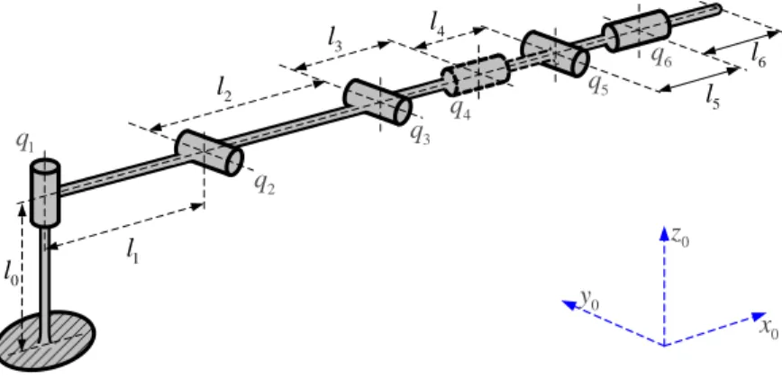
Let us consider elastostatic model of a general serial manipulator, which consists of a fixed “Base”, a serial chain of flexible “Links”, a number of flexible actuated joints “Ac” and an “End-effector” (Figure 1). It is assumed that all links are separated by either rotational or translational joints. Such architecture can be found most of industrial serial robots.
In order to evaluate the stiffness of the considered manipulator, let us apply the virtual joint method (VJM), which is based on the lump modelling approach [64, 65]. According to this approach, the original rigid model should be extended by adding virtual joints (localized springs), which describe elastic deformations of the links. Besides, virtual springs are included in the actuated joints, in order to take into account the stiffness of the control loop. Under these assumptions, the kinematic chain can be described by the following serial structure:
(a) a rigid link between the manipulator base and the first actuated joint described by the constant homogenous transformation matrix TBase;
(b) several flexible actuated joints described by the homogeneous matrix function Joint( Ac)
i i i
q +
T , which depends on the actuated joint variable q and the virtual joint variable i Ac
i
that takes into account the joint compliance; (c) a set of rigid links, which are described by the constant homogenous transformation matrices Linki
T ;
(d) a set of 6-d.o.f. virtual joints that take into account the link flexibility and are described by the homogeneous matrix function VJM( Link)
i
T θ which depends on the virtual joint variables Link ( x, y, z, φx, φy, φz)
i = i i i i i i
θ corresponding
to the translation/rotation deflexions in/around the axis x, y, z;
(e) a rigid link from the last joint to the end-effector, described by the constant homogenous matrix transformation Tool T . ... Link Ac Ac Link Base End-effector ... Link
Ac Rigid Link Link Link 6-d.o.f. spring 6-d.o.f. spring 6-d.o.f. spring
a) kinematic model b) VJM model
Flexible links Actuated joints
w
w
Virtual springs
Figure 1 Serial manipulator and its VJM model
In the frame of these notations, the final expression defining the end-effector location subject to variations of all joint coordinates may be presented as the product of the following homogenous matrices and matrix functions
( )
Base Joint Ac Link VJM Link Tool1 ( ) n i i i i i i q = = +
T T T T T θ T (1)where n is the number of links/joints, and the components Base, , Joint(.), Link, VJM(.), Tool
i i
T T T T T may be factorized with respect to the terms including the joint variables (in order to simplify computing of the derivatives). For further convenience, after extraction from the homogeneous matrix T rotation and translation components [66], the kinematic model can be rewritten in more conventional form
( , ) =
t g q θ (2)
where (.)g denotes relevant vector function, the vector T ( , ) =
t p φ defines the end-effector position T ( , , )x y z = p and orientation T x y z ( , , ) = φ , the vector T 1 2 n ( ,q q , ...,q ) =
q aggregates all actuated coordinates, the vector T
2 nθ
1
( , , ..., ) =
θ collects all virtual joint coordinates, and n is the number of the virtual joints. It should be noted that here θ
the values of coordinates q are completely defined by the robot controller, while the values of the virtual joint coordinates θ depend on the external loading applied to the robot end-effector.
To take into account manipulator stiffness properties, let us assume that variations in the virtual joint variables θ generate the force/torque applied to the corresponding links that are evaluated by the following linear equation (it can be treated as a generalised Hooke's law for the manipulator) τθ =K θ , where θ T
θ =(θ,1,θ,2, ...,θ,nθ)
τ is the aggregated vector of the virtual joint reactions, Kθ =diag(Kθ,1,Kθ,2, ...,Kθ θ,n) is the aggregated virtual spring stiffness matrix, and Kθ,i is the spring stiffness matrix of the corresponding link/joint. Further, let us apply the principle of virtual work assuming that the joints are given small, arbitrary virtual displacements Δθ in the equilibrium neighbourhood. Then, the virtual work of the external wrench w applied to the end-effector along the corresponding displacement Δt=JθΔθ is equal to T
θ) ·
(w J Δθ , where Jθ= f( , ) /q θ θ is the
kinematic Jacobians with respect to the virtual variables θ , which may be computed from (2) analytically or semi-analytically, using the factorization technique proposed in [64]. On the other hand, for the internal forces τ , the virtual work includes only θ one component T
θ Δ
−τ θ . Therefore, since in the static equilibrium the total virtual work is equal to zero for any virtual
displacement, the equilibrium conditions may be written as T
θ = θ
J w τ (3)
This gives additional expressions describing the force/torque propagation from the joints to the end-effector that should be considered simultaneously with the geometric equation (2).
Combining further the virtual joint reaction equation τθ =K θ , the equilibrium condition (3) and the linearized geometric θ model Δt=JθΔθ , it is possible to write statics equations
T
θ =; θ − θ =0
J θ t w J K θ (4)
describing elastostatic properties of the considered manipulator. In these equations, the end-effector displacement Δt is treated as the model input and the external wrench w is the model output, which corresponds to the representation of the manipulator stiffness matrix in the following form
C·Δ =
W K t (5)
where K is the desired Cartesian stiffness matrix of the considered manipulator for given robot configuration q . To find this C matrix, equations (4) may be presented in the matrix form
θ T θ θ = − 0 J w t θ 0 J K (6)
and solved for W . This transformation yields the following force-deflection relation 1 T
θ θ θ Δ
−
=
J K J w t that allows us to
express the manipulator Cartesian stiffness matrix as
(
1 T)
1 C θ θ θ − − = K J K J (7)This expression allows us to compute the Cartesian stiffness matrix assuming that the matrix Kθ =diag(K(1)θ ,K(2)θ , ...), defining elastostatic properties of the manipulator links/joins is given. However, in practice, the matrices
K(i)θ ,i =1, 2,...
are unknown and should be identified from relevant experiments. However, there are a number of numerical problems that may arise here that are in the focus of the remaining parts of the paper.3
Problem of elastostatic parameters identification
3.1
Methodology of elastostatic identification
To estimate the desired matrices describing elasticity of the manipulator components (i.e., compliances of the virtual springs presented in Fig. 1), the elastostatic model (5) should be rewritten as
(
(i) (i) (i)T)
θ θ θ 1 · n i = = t
J k J w (8)where t is the vector of the end-effector displacements under the loading w, the matrices k(i)θ =(K(i)θ )−1 denote the link/joint compliances that should be identified via calibration, and the matrices J are corresponding sub-Jacobians obtained by the (i)θ fractioning of the aggregated Jacobian θ [ (1)θ , (2)θ ,...]
T T
T =
J J J . For the identification purposes, this expression should be transformed into more convenient form, where all desired parameters (elements of the matrices k(i)θ ,i =1, 2,...) are collected in a single vector
(1) (1) ( ) θ11 θ12 θ66 (k ,k ,...kn) =
π . It yields the following linear equation ( , | )· = t A q w π π (9) where 1 1 2 2 ( , | ) [ T , ,...., T ] m m T = A q w π J J w J J w J J w (10)
is so-called observation matrix that defines the mapping between the unknown compliances π and the end-effector displacements t under the loading w for the manipulator configuration q . Below, for the presentation convenience this
matrix will be also referred to as A , where the subscript defines the parameters set for which the observation matrix is
computed. Here, the vectors J are the columns of the matrix i J , i.e. θ Jθ =[ ,J J1 2,....,Jm].
Taking into account that the calibration experiments are carried out for several manipulator configurations defined by the actuated joint coordinates qj,j=1,m, the system of basic equations for the identification can be presented in the following form
( j, j| )· j; 1,
j j m
t =A q w π π ε+ = (11)
where ε denotes the vector of measurement errors. For further convenience, let us also present the system of j m equation (11) in
a matrix form
· ( , | )
a= a a a a
where subscript "a" indicates that matrices/vector aggregate corresponding components for m configurations. Below, the matrix function A q wa( a, a| )π will be also referred to as A . Further, using these notations and assigning proper weights for each a
equation, the identification can be reduced to the following optimization problem
1( ) ( ) min m T T j j j j j F =
= − − → π A π t η η A π t (13)where η is the matrix of weighting coefficients that normalizes the measurement data, Aj = A q w( j, j | )π . This minimization problem yields the following solution
(
) (
1)
1 1 ˆ mj Tj T j · mj Tj T j − = = =
π A η ηA A η η t . (14)If the measurement noise is Gaussian (as it is assumed in conventional calibration techniques), expression (14) provides us with a unbiased estimates for which E
( )
πˆ =π. Corresponding covariance matrix evaluating the dispersion of the parameter estimate ˆπ from one identification session to another can be computed as follows(
)
1(
)
1 2 1 1 1 ˆ cov( ) m T T m T T T m T T j j j j j j j j j − − = = = =
η η
η η η η
η π A A A Σ A A ηA (15)where the matrix Σ2=E( ·ε ε describes the statistical properties of the measurement errors. T)
It can be proved [67] that the best results in terms of the identification accuracy are achieved if η Σ . It leads to the = −1 following covariance matrix of the manipulator compliance parameters
(
)
1 1 1 ˆ cov( ) mj Tj T j − − − = =
π A Σ Σ A (16)Such assignment of the weighing coefficients η also allows us to avoid the problem of different units in the objective function (13), which arises in straightforward application of the leas-square technique to the robot parameters identification if the measurement system provides both position and orientation data. It should be noted that this particularity is usually omitted in conventional robot calibration. Another way to improve the identification accuracy is related to the proper selection of manipulator measurement configurations
qj,j=1,m
that is also known as the calibration experiment planning [68], which directly influences on the observation matrices A q w( j, j| )π and on the covariance matrix (16).It is clear that expression (14) gives reliable estimates of the parameters π if and only if the matrix 1 1 m T T j j j − − =
A Σ Σ A isinvertible. It leads to the problem of the parameter identifiability that have been studied by a number of authors for the problem of geometrical calibration [62, 63]. Relevant techniques are based on the information matrix rank analysis (via either SVD- or QR-decomposition). However, in real industrial practice where the measurement not is non-negligible, the identifiable parameters are not equivalent in terms of accuracy (both absolute and relative) and expression (14) can give rather surprising results for some of them. This motivates revision of the above mentioned notion (parameter identifiability) and its extension taking into account the identification accuracy defined by the covariance matrix (16). In the following sub-sections, the notion of
practical identifiability is introduced and a motivation example is presented, which illustrates potential problems that may arises
in the manipulator elastostatic calibrations if conventional techniques are applied.
3.2
Difficulties in elastic parameters identification
To illustrate the problems that may arise in identification of the manipulator elastostatic parameters, let us consider a numerical example that deals with a single link of the Orthoglide manipulator (Figure 2). Its compliance matrix has been obtained in [64] and is equal to 8 5 4 5 4 3 4 3 4 3 4.50·10 0 0 0 0 0 0 8.01·10 0 0 0 3.98·10 0 0 3.64·10 0 1.71·10 0 0 0 0 3.76·10 0 0 0 0 1.71·10 0 1.09·10 0 0 3.98·10 0 0 0 2.65·10 − − − − − − − − − − − = − k (17)
(a) Principal link of Orthoglide manipulator (b) Architecture of Orthoglide manipulator
W
Figure 2 Manipulator link considered in the motivation example
Let us simulate the calibration process assuming that the matrix (17) should be estimated by means of the identification algorithm described above, where the input data are generated by means of virtual experiments. In the frame of these experiments, the link is assumed to be fixed on one side and the external loading w is applied on the another side. For each loading, the j
corresponding deflection vector is computed in accordance with expression tj=k w· j+εj, where ε is the measurement noise. j
In accordance with the physical properties of the examined link and to conserve the linearity of the force-deflection relation, the loading magnitude has been limited by 10N for the forces and 10Nm for the torques. The measurement noise magnitude has been defined as p=25m for the positional components and as =0.25mrad for the orientation components (these values correspond to the precision of the best industrial measurement systems that currently are available on the market). These virtual experiments has been carried out six times, in order to obtain sufficient number of equations for the identification of 36 desired parameters k . ij
For these virtual experiments, the properties of the observation matrix used in the identification expression are quite good: rank is equal to 36 and the condition number is 1.00. Nevertheless, the identification are rather "surprising": the obtained compliance matrix essentially differs from the original one and is
8 7 7 8 7 7 7 7 7 7 7 7 7 7 6 7 8.71·10 1.86·10 1.59·10 7.72·10 1.15·10 4.53·10 2.07·10 1.98·10 1.14·10 2.29·10 3.76·10 2.25·10 1.13·10 1.42·10 1.83·10 7.05·1 ˆ 0 -8 -5 -4 -5 -4 -3.05·10 8.05·10 3.98·10 3.65·10 -1.71·10 3 − − − − − − − − − − − − − − − − − − − − = − k 6 6 6 6 6 6 6 6 7 8 1.11·10 4.12·10 3.27·10 1.23·10 3.99·10 5.07·10 2.61·10 1.06·10 2.81·10 4.58·10 -3 -4 -3 -4 -3 .76·10 -1.68·10 1.09·10 3.97·10 2.65·10 − − − − − − − − − − − − − − (18)
Detailed comparison analysis of the original matrix k and its estimate ˆk allows us to make the following conclusions concerning the harmful impact of the measurement noise on the identification of the elastostatic parameters in real industrial environment:
(i) the obtained compliance matrix ˆk may lose the properties of positive-definiteness, which completely contradicts to the common physical sense that is based on the energy-based definition of k (in particular, in the above −1
example, kˆ110 is not acceptable);
(ii) the obtained matrix ˆk may be non-symmetric, which also contradicts to the physical sense (for instance, ˆk53 and 35
ˆk , which corresponds to non-zero elements of k, are not equal and differ by 2%);
(iii) for some small elements, the identification accuracy may be extremely low (for example the element ˆk11, which is 3
~ 10 times less than ˆk22 and ˆk33 has been identified completely wrongly);
(iv) in the obtained matrix ˆk, the number of non-zero elements is redundant compared to the original matrix k; moreover, it is difficult to distinguish small elements kˆij from so-called zero elements, which correspond to exact
zeros in k induced by the physical properties of the examined link (for instance, the element ˆk21 that should be equal to zero by definition is the same order of magnitude as ˆk11, which should be small but strictly positive); (v) for the remaining elements, whose magnitude is high enough, the identification errors are quite acceptable (from
0.01% to 1.67%), but they should be further reduced by increasing number of the experiments.
It should be noted that for essentially lower measurement noise (with and p that are 100 times smaller) the above
mentioned problems do not exist, however such measurement precision is not achievable in industrial environment at present. Hence, as follows from this motivation example, the whole set of 36 elastostatic parameters
kij composing the 6 6 matrixelements, corresponding deflections under the admissible loading are comparable with the measurement noise. To detect these indistinct elements, a simple indicator can be applied showing parameter-to-noise ratio (which is similar to signal-to-noise ratio in communication): 0.35 0.74 0.64 0.31 0.46 1.81 0.83 0.79 0.46 ˆ | | 0.91 1.50 0.89 0.45 0.06 0.73 0.28 0.44 1.64 1.31 0.49 1.60 2.02 1.04 0.42 0.11 0.02 ij ij 0.12 322 1593 146 684 1504 -67.3 436 159 1060 k = (19)
where is a corresponding element of the relevant covariance matrix. As follows from these numerical values, 27 of 36 desired ij
parameters can be hardly estimated from the experimental data with realistic measurement noise. Only for 9 parameters k , 22 k , 26 33
k , k , 35 k , 44 k , 53 k , 55 k , 62 k the ratio is high enough (more than 50), so they can be treated as "practically identifiable". It 66 should be stressed that similar indicators computed using exact values of k (which are unknown in practice) give similar result ij
0.18 0 0 0 0 0 0 320 0 0 0 1592 | | 0 0 146 0 684 0 0 0 0 1504 0 0 0 0 68.4 0 436 0 0 159 0 0 0 1060 ij ij k = (20)
allowing us to detect the same set of small or zero parameters whose identifiability is questionable. On the other side, the impact of these parameters on the elastostatic deflections is so small that they can be reasonably excluded from the desired stiffness model. These results confirm importance of the above pointed problems, which below are considered in details.
Summarising theoretical background and simulation results presented above, it is possible to make the following conclusions: (i) complete elastostatic model of robotic manipulator includes huge number of parameters (258 for conventional 6 d.o.f. serial robot), whose simultaneous identification in presence of measurement noise is rather difficult or even impossible;
(ii) before applying the least-square identification technique , the manipulator elastostatic model should be reduced and
redundant parameters should be eliminated, in order to ensure invertibility of the information matrix; this step can
be performed using techniques similar to those developed for the geometrical calibration;
(iii) among the remaining non-redundant parameters, there are a number of non-significant ones, whose absolute values are relatively small, the identification accuracy is quite low and the impact on the compliance of the of the entire manipulator is almost negligible; these parameters can be treated as "practically non-identifiable" and should be also eliminated from the model, but relevant techniques are not available yet;
(iv) while developing relevant techniques allowing detection of "practically identifiable" parameters, it is prudent to take into account some specific properties of the compliance matrices induced by the elasticity physics such as the compliance matrix symmetry, presence of strictly zero elements (matrix sparseness), positive-definiteness, etc. Hence, to obtain reliable stiffness model that is suitable for calibration, and that contains only significant and practically identifiable parameters while describing manipulator elastostatic properties sufficiently good, it is necessary to develop dedicated model reduction techniques and relevant rules allowing us to minimise number of parameters to be estimated and to reconstruct the original VJM-based model from these data taking into account mathematical relations between the model parameters caused by their physical sense.
4
Practical identifiability in manipulator calibration
4.1
Basic assumptions and terminology
Let us assume that the vector of desired elastostatic parameters π should be identified from the set of the linear equations (11) whose least square solution is defined by the expression (14), where the observation matrices A q w( j, j| )π are computed for certain set of measurement configurations
qj and loadings
wj . Depending on the matrix set
Aj , corresponding systemof linear equations can be solved for π either uniquely or may have infinite number of solutions. In general, if the information matrix is rank-deficient, a general solution of the system (11) can be presented in the following form
(
)
ˆ = +· + − + ·π A B I A A λ . (21)
where the superscript "+" denotes the Moore–Penrose pseudoinverse, A =
mj=1ATjη ηT Aj , 1m T T
j j
j
=
= η ηB A t and λ
is an arbitrary vector of the same size as π. Using the later expression, all desired parameters contained in the vector π can be divided into the following groups [63]:
G1: Identifiable parameters that can be obtained from (21) in unique way and are independent from the arbitrary vector
λ;
G2: Non-identifiable parameters that cannot be computed uniquely from (21) and can take on any value without
influence on the right-hand side of the equation (9), they correspond to the zero columns of the observation matrix
A ;
G3: Semi-identifiable parameters that are also cannot be computed uniquely but have influence on the right-hand side of
the equation (9); they are united in subgroups where a single one can be treated as identifiable if the remaining ones are fixed.
To present typical examples of the parameters belonging to the groups G1, G2 and G3, it is possible to use the ideas similar to geometrical calibration. For instance, the elastostatic parameters of the actuated joints and adjacent links are redundant in their totality and belong to the group G3. Besides, if the loading direction cannot be altered, a number of parameters belong to the group G2 and cannot be identified from the corresponding experimental data. So, complete and irreducible model should contain all parameters from the group G1 and partially parameters of the group G3. More details on issue will be given in Section 4.3.
In this paper, in contrast to previous works, this classification is enhanced taking into account practical issues related to the limited precision of the measurement system. The main idea is to compare the absolute value of the estimated parameter with the range of possible fluctuations of the estimate caused by the measurement noise. For computational reasons, it is convenient to introduce a numerical indicator similar to the signal-to-noise ratio in communication, which is defined as follows
ˆ / , 1, 2,...
i i i i
= = (22)
where i is the standard deviation of the parameter estimate ˆi extracted from the diagonal of the covariance matrix (16). It is
clear that i can be treated as the inverse of the relative accuracy, which allows us to avoid the problem of division by zero. In the
following sections this indicator will be referred to as parameter-to-noise ratio.
Using the above defined indicator, the set of parameters belonging to the group G1 (theoretically identifiable) can be further divided into three subgroups:
G1+: Practically identifiable parameters, for which the accuracy indicator is high: i 0 +
; this subgroup describes principal elastostatic properties of the manipulator and should be certainly included in the reduced model used in the identification routines;
G1-: Practically non-identifiable parameters, for which the accuracy indicator is low: i 0−; this subgroup contains non-essential parameters that can be assigned to zero in the VJM-model without essential impact on its precision (in practice, the majority of these parameters are nominally equal to zero due to the physical nature of the compliance matrices);
G1~: Practically semi-identifiable parameters, for which the accuracy indicator is intermediate: 0 i 0 − +
; the parameters belonging to this subgroup are practically non-identifiable for the current experimental setup but, hypothetically, can be converted into practically identifiable ones by increasing the experiment number, improving the measurement precision of by modification of the measurement configurations.
An open question however is related to justified assigning of the upper and lower bounds 0+ and 0−. From practical point of view that is adopted below, it is reasonable to use 0+ = and 5 0−= , which is in a good agreement with the quantiles of the 2 normal distribution. However, the user may modify these values in accordance with the specificity of the problem of interest.
The above presented definitions allow us to revise the concept of "suitable-for-calibration" model that in previous works included all parameters of the group G1 (this model is also referred to as the "complete and irreducible" one). In this work, this model is limited to include only parameters of the subgroup G1+ (practically identifiable) that can be estimated with reasonable accuracy and provide good approximation of the original complete model. The following subsections address different aspects of model reduction allowing us to obtain the desired model suitable for the elastostatic calibration.
It should be noted that, in spite of the fact that the main focus of the paper is on the elastostatic modelling, similar ideas can be also successfully applied in manipulator geometric calibration.
4.2
Model reduction: physical approach (
π→π)
Straightforward approach to the manipulator stiffness modelling leads to the exhaustive but redundant number of parameters to be identified. For instance, each links is described by a 6 6 matrix that includes 36 parameters that are treated as independent ones. However, as follows from physics, number of the pure physical and independent parameters is essentially lower (for a trivial prismatic beam, for example, there are only five physical parameters: three describing the geometry and two describing the material properties). Hence, there are strong relations between these 36 parameters but this fact is usually ignored in elastostatic calibration. Besides, due to fundamental properties of conservative system, the desired compliance matrices should be strictly symmetrical and positive-definite. In addition, for typical manipulator links, the compliance matrices are sparsed due to the shape symmetry with respect to some axis, but this property is also not taken into account in identification of the elastostatic parameters. To take advantages of the compliance matrix properties and to increase the identification accuracy, two simple methods can be applied that allows us to reduce the number of parameters to be computed in the identification procedure (14). They can be treated as the physics-based model reduction techniques and formalised in the following way.
M1:Symmetrisation. For all compliance matrices k to be identified, replace the pairs of symmetrical parameters
kij,kji
by a single one kij,i .jFor each link, this reduction procedure is equivalent to re-definition of the model parameters vector in the following way
· =
π M π (23)
where the binary matrix M of size 36 21 describes the mapping from the original to reduced parameter space. It can be proved that corresponding basic expression for the identification (9) can be rewritten as
( , | )· =
t A q w π π (24)
where A q w( , |π =) A( ,qw π| )·M denotes the reduced observation matrix. The later can be also computed as
θ 1 θ θ 2 θ θ 21 θ
( , | =) [ T , T , ... T ]
A q w π J ω J w J ω J w J ω J w (25)
where ω ω1, 2,... denote the binary matrices of size 6 6 for which non-zero elements (i.e. equal to 1) are located in the following way: for the parameter l corresponding to the matrix elements kij,i , the non-zero elements are j ij =ji = . It is clear that 1
this idea allows us to reduce the number of links compliance parameters from 36 to 21 (and from 258 to 153 for the entire 6 d.o.f. manipulator).
M2:Sparcing. For all compliance matrices k to be identified, eliminate from the set of unknowns the parameters kij
corresponding to zeros in the stiffness matrix template 0
k derived analytically for the manipulator link with similar
shape.
To obtain a desired template matrix, is convenient to use any realistic link-shape approximation. For example using the trivial beam [69], the desired template can be presented as
0 * 0 0 0 0 0 0 * 0 0 0 * 0 0 * 0 * 0 0 0 0 * 0 0 0 0 * 0 * 0 0 * 0 0 0 * = k (26)
where the symbol "*" denotes non-zero elements. It allows further reducing the number of the unknown parameters from 21 to 8, taking into account only essential ones from physical point of view. It can be also proved that the template (26) is valid for any link whose geometrical shape is symmetrical with respect to three orthogonal axes. But it is necessary to be careful if this property is not kept strictly.
It should be stressed that the actuated joint compliances cannot be identified separately. So, they should be included in the compliance matrix of the previous link by means of modification of the corresponding diagonal elements.
M3:Aggregation. Eliminate from the set of model parameters the ones that corresponds to joint compliances before
which there is an elastic link; in terms of parameters identifiability the compliance of those joints cannot be split from the links.
Summarizing these methods, it should be mentioned that the above presented approach essentially reduce the number of parameters to be identified (by the factor 4.5) but they do not violate such basic properties as the mode completeness, i.e. the ability to describe any deflection caused by the external loading. Below, these reduced set of the original model parameters π
will be referred to as π . However, the obtained reduced model may still have some redundancy in the frame of entire manipulator, where the virtual springs of adjacent joints/actuators cause similar impact on the end-effector deflections under the loading.
To illustrate efficiency of the methods M1 and M2, the identification problem considered in section 3.2 have been solved for reduced set of the compliance parameters. It yielded the following result
8 5 4 5 4 3 4 3 4 3 3.05·10 0 0 0 0 0 0 8.05·10 0 0 0 3.98·10 0 0 3.64·10 0 1.71·10 0 0 0 0 3.76·10 0 0 0 0 1.71·10 0 1.09·10 0 0 3.98·10 0 0 0 2.6510 ˆ · − − − − − − − − − − − − = − k (27)
which is essentially better compared to (18). In particular, the identification errors for the most of the desired parameters are less than 0.4%, i.e. 4 times lower. The only exception is the small element ˆk11 that is still negative and contradicts to the physical sense. This motivates further efforts to obtain reliable stiffness model whose parameters can be calibrated in real industrial environment.
From the geometrical calibration it is known that in spite of the fact that redundant model is suitable for direct and inverse computations it cannot be used in identification since the observation matrix does not have sufficient rank. Similar problem arises in elastostatic calibration where some stiffness matrix elements of adjacent links/joints are coupled and cannot be identified separately. The problem of construction complete and irreducible model has been widely studied in geometrical calibration and the developed techniques can be adopted for the elastostatic calibration.
4.3
Model reduction: algebraic approach (
π→π)
The physical approach described in the previous sub-section allows us essentially reducing the number of model parameters. However, it does not guarantee that the obtained model is suitable for calibrations (i.e. that the model is non-redundant and the number of parameters is equal to the observation matrix rank). In practice, the following inequality is often satisfied:
(
)
(
a a, a|)
dim( )
rank A q w π π . To overcome the problem, this sub-section presents some algebraic tools aimed at further reduction of the model parameter set from π to π , which ensures full identifiability:
(
)
(
a A, a|)
(
a(
a, a|)
)
dim( )
rank A q w π =rank A q w π = π (28)
These tools are based on the partitioning of the parameters set π into three non-overlapping groups (identifiable, non-identifiable and semi-identifiable), which are either eliminated from the model or reduced to ensure the equality (28).
To introduce relevant algebraic technique, let us apply the SVD decomposition and present the aggregated observation matrix
(
, |)
a a a
A q w π as the product of three matrices U Σ V· · T (orthogonal, diagonal and orthogonal, respectively):
(
)
(
)
(
)
1 1 1 1 2 2 2 ' 2 1 ' ' ' 2 0 0 , | 0 0 , | · · 0 , ,.. 0 , | . c c T T r n T n m r m r m m m n = U A q w π V A q w π 0 V A q w π 0 V U U 0 (29)Here U U U=[ , ,... ]1 2 U andm V V V V are orthogonal matrices of the size =[ , ,... ]1 2 v m m and n n respectively whose columns
are denoted as U and i V ; the second factor j Σ is a rectangular diagonal matrix of the size m n containing r positive real
numbers 1, ,...2 r in descending order; m =dim
(
ta)
is the number of rows in the observation matrix (i.e. number ofequations used for the identification), n=dim
( )
π is current number of the model parameters, and r is the rank of theaggregated observation matrix, m m r'= − , n n r'= − . It is clear that r defines the maximum number of parameters that can be identified using given set of manipulator configurations
qi and corresponding wrenches
wi .Further, after substitution (29) into (12) and left-multiplication by UT, the original system of m identification equations (12)
1 1 1 2 ' 2 2 ' ' ' 0 ... 0 0 ... 0 ... ... ... · · · ... ... 0 0 ... r T T T T r n a T T n m m r m n = V U 0 V π U t V U 0 0 ... ... ... ... ... ... (30)
where the number of equation is equal to n and perfectly corresponds to the vector π dimension (it is obvious that n m ).
Taking into account particularities of the sparse matrix Σ (with r non-zero elements only), it is possible to rewrite the system
(30) in the form ; · · · 1,2,..., 0· · · ; 1,. .., T i T i T i i a T i a i r i r n = = + = = U V π t V π U t (31)
where the second group of m m r'= − equations should be excluded from further consideration because relevant residuals do not depend on the parameters of interest π (since they are multiplied by zero matrix). It can be proved that T· a
i t
U 0 for i r if the measurement vector ta does not contain noise. It is also worth mentioning that for real identification problems (with the
measurement noise), the second group of equations produces constant residuals that cannot be minimised in the least-square objective (13) by varying the vector of unknown parameters π .
Hence, for the identification of n parameters included in the vector π , a system of r linear equations have been obtained that cannot be solved uniquely in a general case. Its partial solution can be found by dividing on i0 each of r linear equations · ·T ·
i i Ti a
V π =U t and further straightforward multiplication of the left and right sides by the matrix
V1,V2,. ,..Vr
,which yields
1 1 1 2 2 2 1 2 1 2 / / ,..., · ,..., · ... ... , / , T T T T r r a T T r r r = V U V U V V π V V t V U V V (32)Using the first set of r equations of system (31) one can obtain partial solution of system (30)
(
1)
0 1 · · r T i i i a i − = =
π V U t (33)This allows us to present the general solution (21) as the sum of this partial solution and an arbitrary vector from the subspace with the basis V Vr+1, r+2,...Vn 1 ˆ o n i i i r = + = +
V π π (34)where i, i r= +1,n are arbitrary real values.
Hence, as follows from analysis of (31) and (34), depending on the properties of the matrix V , all model parameters π can
be partitioned into three groups: G1 − identifiable parameters that are uniquely defined by the equation (34) and do not depend on the arbitrary values i, for these parameters the corresponding row of the sub-matrix [Vr+1,..., ]V is equal to zero; G2 −m
non-identifiable parameters that do not effect the residuals of system (31), for these parameters the corresponding row of the
sub-matrix [ ,..., ]V1 V is equal to zero; G3 − semi-identifiable parameters that effect the residuals but cannot be identified r
uniquely, couplings between these parameters is defined by the vectors V ,i i=1,r. Thus, based on this decomposition, the algebraic-based model reduction techniques can be formalised in the following way:
M4a:Partitioning. Divide the reduced set of the model parameters π into three non-overlapping groups G1, G2 and G3 in accordance with the following rules applied to all i , i =1,dim( )π :
Rule 1: Include the parameter i into the group G1 if the ith row of the sub-matrix [Vr+1,..., ]V is equal to zero;m
Rule 2: Include the parameter i into the group G2 if the ith row of the sub-matrix [ ,..., ]V1 V is equal to zero;r
Rule 3: If the parameter i is not included in G1 or G2, include it in the group G3.
M4b:Elimination. Eliminate from the set of unknowns (model parameters) non-identifiable parameters that correspond


![Table 5 Compliance error compensation efficiency for full and reduced set of model parameters Residuals Coordinate-based Distance-based max RMS max RMS Deflections magnitude, [mm] 33.9 9.3 34.8 16.7 Deflections prediction errors, [μm]](https://thumb-eu.123doks.com/thumbv2/123doknet/11508024.293985/18.918.91.860.122.274/compliance-compensation-efficiency-parameters-residuals-coordinate-deflections-deflections.webp)