HAL Id: hal-02409856
https://hal.archives-ouvertes.fr/hal-02409856
Submitted on 27 Nov 2020
HAL is a multi-disciplinary open access
archive for the deposit and dissemination of sci-entific research documents, whether they are pub-lished or not. The documents may come from teaching and research institutions in France or abroad, or from public or private research centers.
L’archive ouverte pluridisciplinaire HAL, est destinée au dépôt et à la diffusion de documents scientifiques de niveau recherche, publiés ou non, émanant des établissements d’enseignement et de recherche français ou étrangers, des laboratoires publics ou privés.
Ni 1-x Co x O y , Ni 1-x Co x S y and Ni 1-x Co x P y
Catalysts Prepared from Ni 1-x Co x -ZIF-67 for
Hydrogen Production by Electrolysis in Alkaline Media
Yuchen Cui, Zhi Liu, Hailing Guo, Yongming Chai, Chenguang Liu, Svetlana
Mintova
To cite this version:
Yuchen Cui, Zhi Liu, Hailing Guo, Yongming Chai, Chenguang Liu, et al.. Ni 1-x Co x O y , Ni 1-x Co x S y and Ni 1-x Co x P y Catalysts Prepared from Ni 1-x Co x -ZIF-67 for Hydrogen Production by Electrolysis in Alkaline Media. ChemCatChem, Wiley, 2019, 11 (20), pp.5131-5138. �10.1002/cctc.201901385�. �hal-02409856�
Ni
1-xCo
xO
y, Ni
1-xCo
xS
yand Ni
1-xCo
xP
ycatalysts prepared from Ni
1-xCo
x-ZIF-67 for hydrogen production by electrolysis in alkaline media
Yuchen Cui[a], Zhi Liu[a], Hailing Guo*[a], Yongming Chai[a], Chenguang Liu[a], Svetlana Mintova[a,b]a State Key Laboratory of Heavy Oil Processing, Key Laboratory of Catalysis, China National Petroleum
Corp. (CNPC) China University of Petroleum (East China), Qingdao 266555, People's Republic of China.
b Laboratoire Catalyse et Spectrochimie (LCS), Normandie University, ENSICAEN, UNICAEN, CNRS,
6 boulevard du Marechal Juin, 14050 Caen, France
* Corresponding author: Prof. Hailing Guo, Fax: +86 0532 86981787, Tel: +86 0532 86984688 and
Abstract: The uniform homeotypic bimetallic Ni1-xCoxOy, Ni1-xCoxSy and Ni1-xCoxPy catalysts were
synthesized from Ni1-xCox-ZIF-67 crystals (120-135 nm) reacting with oxygen, sublimed sulfur and
sodium hypophosphite, respectively under control conditions. The catalysts were deposited on glassy
carbon electrode (GCE), and their electro-catalytic activity for hydrogen production in alkaline media by
electrolysis was investigated. The electrocatalytic activity of the catalysts towards hydrogen evolution
reaction (HER) decreased in the following order Ni0.1Co0.9Py>Ni0.2Co0.8Oy>Ni0.5Co0.5Sy>Ni0.1Co0.9
-ZIF-67. The Ni0.1Co0.9Py exhibited the highest electrocatalytic activity towards HER due to the high
crystallinity, high specific surface area and the synergistic effect of nickel and cobalt that accelerate the
electron transfer process.
Introduction
Transition metals have been recently suggested as appropriate catalysts for hydrogen evolution
reaction (HER)[1]. The transition metal catalysts are used in alkaline media, and the alkaline water
electrolysis is a competitively priced process in comparison to proton exchange membrane water
electrolysis [2]. Due to the low cost, environmental benign, and high theoretical catalytic activity,
Co-based materials are particularly attractive among other transition metal-Co-based electrocatalysts for water
splitting [3]. Multiple methods were used to prepare Co-based materials. For instance, Co4N was
synthesized by simple nitridation reaction and high temperature treatment with Co(OH)F nanowire
arrays[3c]. CoO nanorods (NRs) were fabricated by surface strain engineering [4].
Metal-organic frameworks (MOFs) materials have been recently proven to be promising sacrificial
template or self-template to produce electrocatalysts due to their sufficient exposed active sites, abundant
organic ligands, and mesoporous structure[5]. For example, Li et al.[3a] synthesized Co
3O4 nanocrystals
embedded in N-doped mesoporous graphitic carbon layer/multiwalled carbon nanotube (MWCNT)
hybrids by a facile carbonization and subsequent oxidation of MWCNT-based MOFs, which leaded to
high electrochemical performance. In 2017, Cao et al.[3d] reported the preparation of hollow CoS
2 tubular
self-agglomeration of Co-MOFs materials usually leaded to a high overpotential and decreased reaction
rate.
In order to improve the efficiency and avoid self-agglomeration of Co-based materials, it is important
to understand the structure-activity relationship between their electrocatalytic activities and the dispersion
and valence state of the Co-based materials[6]. Different Co-based materials including sulfides, oxides,
phosphides[7], etc. show diverse electrocatalytic activity for HER[8] [9].In addition, reducing the size of
particles of Co-based materials, especially going to ultra-small nanoclusters or even single atoms[10], is
considered as an effective way to improve their catalytic performance. Furthermore, the introduction of a
second metal component in the Co-based materials improved the resistance to corrosion in the alkaline
media, and prevented the Co nanoparticles from agglomeration [11]. Several investigations have focused
on MOF-derived bimetallic or multi-metallic derivatives, leading to advanced electrocatalytic
performance compared with single Co-based materials [12]. For examples, He and co-workers fabricated
carbon containing Ni–Co mixed metal phosphide nanoboxes (NiCoP/C) by ZIF-67[12a]. Liang and et al.
reported the Ni2P-CoP bimetallic phosphides derived from the NiCo-MOFs, which showed efficient
performance for both HER and the oxygen evolution reaction (OER) [12c]. Mostly Co-MOFs under thermal
decomposition conditions in the presence of a second metal were applied to fabricate new multi-metallic
materials[13]. Firstly, the Co-MOFs was prepared, then the second metal (Ni) under acidic etching or
thermal decomposition was introduced resulting in mesoporous structures collapse with
self-agglomerated metals. The preparation of nanosized homogenous bimetallic MOFs derivatives for HER is
Scheme 1. Schematic diagram representing the preparation of Ni1-xCox-ZIFs-67, Ni1-xCoxOy, Ni1-xCoxSy
and Ni1-xCoxPy from Ni1-xCox-ZIFs-67
This article reports the preparation of homeotypic bimetallic catalysts (Ni1-xCoxOy, Ni1-xCoxSy and
Ni1-xCoxPy) using nanosized bimetallic precursor Ni1-xCox-ZIF-67 (Scheme 1). The uniform bimetallic
Ni1-xCox-ZIF-67 crystals (120-135 nm) were prepared from Co-ZIF-67 at low temperature (0℃) (see
Experimental Section). Hence the Ni1-xCox-ZIF-67 were allowed to convert into Ni1-xCoxOy, Ni1-xCoxSy
and Ni1-xCoxPy materials by temperature-programmed reactions with oxygen, sublimed sulfur and sodium
hypophosphite, respectively. Then, the homeotypic bi-metallic materials were deposited on glassy carbon
electrode (GCE) and applied in alkaline (pH=14) electrolysis for hydrogen production. The effect of the
state of Ni and Co species on the electrocatalytic performance of the catalysts for hydrogen evolution in
alkaline media was studied in detail.
Results and Discussion
Characterization of NixCo1-x-ZIF-67, NixCo1-xOy, NixCo1-xPy, and NixCo1-xSy catalysts
The crystal structure of Co-ZIF-67 and Ni0.1Co0.9-ZIF-67 was characterized by XRD. The XRD
diffraction pattern of Ni0.1Co0.9-ZIF-67 is similar to the mono-metallic Co-ZIF-67 sample (Fig. 1a).
S1a, the XRD patterns of samples NixCo1-x-ZIF-67 with different Ni/Co ratios contain broad peaks, but
their positions are identical with the simulated pattern of Co-ZIF-67[14]. No impurity was found in samples
NixCo1-x-ZIF-67, implying that Ni2+ ions are effectively incorporated into the Co-ZIF-67[15]. The intensity
of the peaks for NixCo1-x-ZIF-67 (Fig.S1a) decreased with an increase of nickel content, which is related
to the changes of charge distribution and electrostatic fields as a result of the existence of both nickel and
cobalt within the framework[16]. While the XRD patterns of samples Co3O4 and Ni0.2Co0.8Oy (Fig. 1b)
contain peaks at 31.3°and 36.8°2Theta corresponding to (100) and (101) planes of Co3O4[17], and a peak
at 43.0° corresponding to (200) plane of NiO[11c, 18]. This result indicates that the NixCo1-x-ZIF-67 is fully
transformed to Ni0.2Co0.8Oy. The XRD patters of samples CoP and Ni0.1Co0.9Py are shown in Fig. 1c. The
Bragg peaks at 31.6, 36.6, 46.3 and 48.7° 2Theta correspond to the (011), (111), (112) and (211) planes
of CoP[3b, 12a, 12c], and the peak at 41.0° 2Theta corresponds to (321) plane of Ni3P[12b, 19], which confirm
the transformation from NixCo1-x-ZIF-67 to CoP and Ni0.1Co0.9Py. The nanosized bimetallic atomic
arrangement in the NixCo1-x-ZIF-67 is demonstrated as well (Fig. S1c). The XRD patterns of Co9S8 and
Ni0.5Co0.5Sy samples are depicted in Fig. 1d. The peaks at 15.3, 29.8, 31.2 and 47.5° 2Theta correspond
to (111), (311), (222) and (511) planes of Co9S8 [20], and the peak at 44.4° is related to the (102) plane of
Figure 1. XRD patterns of Co-ZIF-67 and Ni0.1Co0.9-ZIF-67 (a), Co3O4 and Ni0.2Co0.8Oy (b), CoP and
Ni0.1Co0.9Py (c) and Co9S8 and Ni0.5Co0.5Sy (d).
Figure 2. SEM images of Co-ZIF-67 (a), Ni0.1Co0.9-ZIF-67 (b), Co3O4 (c), Ni0.2Co0.8Oy (d), CoP (e),
The SEM images for all samples (Co-ZIF-67 and Ni0.1Co0.9-ZIF-6, Co3O4 and Ni0.2Co0.8Oy, CoP,
Ni0.1Co0.9Py, Co9S8 and Ni0.5Co0.5Sy) are presented in Fig. 2. The Co-ZIF-67 crystals (Fig. 2a) have a
diameter of 86 nm and nearly spheroidal shape. As shown in Fig. 2b, the Ni0.1Co0.9-ZIF-67 crystals have
similar morphology and a size of 135 nm. After oxidation, the derived Co3O4 crystals (Fig. 2c) have
dodecahedral shape with an average size of 300 nm, while the Ni0.2Co0.8Oy crystals have an average size
of 206 nm (Fig. 2d). The crystal size of the samples increases about twice after oxidation of the NixCo
1-x-ZIF-67, indicating that two or three NixCo1-x-ZIF-67 nanoparticles coalesce into one NixCo1-xOy particle.
In the case of phosphides, the derived CoP showed an average size of 34 nm (Fig. 2e), and the Ni0.1Co0.9Py
crystals have an average size of 23 nm (Fig. 2f), which are smaller than the NixCo1-x-ZIF-67. The derived
Co9S8 crystals have an average size of 15 nm (Fig. 2g), while the Ni0.5Co0.5Sy has a size of 12 nm (Fig.
2h), which are considerably smaller than the NixCo1-x-ZIF-67 crystals. The energy dispersive X-ray (EDS)
elemental mapping and the elements proportion presented in Fig. S3 also confirm the uniform distribution
of all elements in the Co-ZIF-67 (a) (Co ,C ,N ,O), Ni0.1Co0.9-ZIF-67 (b) (Co, Ni), Co3O4 (c) (Co, O),
Ni0.2Co0.8Oy (d) (Ni, Co, O), CoP (e) (Co, P), Ni0.1Co0.9Py (f) (Ni, Co, P), Co9S8 (g) (Co, S) and Ni0.5Co0.5Sy
(h) (Ni, Co, S). Additionally, the chemical composition of the materials was characterized by ICP-AES
(Table S1). The content of metals (Co & Ni) in the oxide, sulfide and phosphide is much higher than in
the Co-ZIF-67 and Ni0.1Co0.9-ZIF-67 samples, indicating that most of the C, N and H elements were
pyrolyzed after the high-temperature treatment and the target products were prepared successfully.The
transmission electron microscopy (TEM) images for all samples (Co-ZIF-67 and Ni0.1Co0.9-ZIF-6, Co3O4
and Ni0.2Co0.8Oy, CoP, Ni0.1Co0.9Py, Co9S8 and Ni0.5Co0.5Sy) are shown in Fig. S2. The TEM results are
consistent with SEM. The Ni0.1Co0.9-ZIF sample contains the same Co lattice with a Co-ZIF-67(111)
interlayer spacing of 0.20 nm (Fig. 2a,b). The lattice fringes of Co3O4 and Ni0.2Co0.8Oy display interplanar
spacings of 0.24 nm, which match well with the (311) planes of the Co3O4 (Fig. 3c,d).TEM images reveal
that the Ni0.1Co0.9Py retained small size with rough surface (Fig. S2 e,f). Moreover, the resolved
interplanar distances of 0.09 and 0.12 nm from the HRTEM image can be ascribed to the (211) and (111)
similar sizes are revealed by both TEM and SEM.The carbon cladding outside the metal particles (Fig.
S2g), the carbon layer of the entire nanoparticle are evenly formed and thinner (Fig. S2h); the
carbon-coated metal particles can be clearly seen. The interplanar distances of 0.14 and 0.15 nm resolved from
the HRTEM image are ascribed to the (311) and (222) planes of Co9S8, respectively (Fig. S2 g,h insert
image).
Figure 3. FT-IR spectra of Co-ZIF-67 and Ni0.1Co0.9-ZIF-67 (a), Co3O4 and Ni0.2Co0.8Oy (b), CoP
and Ni0.1Co0.9Py (c), Co9S8 and Ni0.5Co0.5Sy (d)
The N2 adsorption-desorption study was applied to reveal the porous nature of the samples (Figure
S4). The specific surface area of samples Co-ZIF-67 and Ni0.1Co0.9-ZIF-67 is 1402.4 m2g−1 and 1242.8
m2g-1,respectively. The isotherm of Co-ZIF-67 and Ni0.1Co0.9-ZIF-67 are identified as type I, which is
pore size distribution curve further indicates that Co-ZIF-67 contains the micropores. The BET specific
surface area for sample Co3O4, is 2.2 m2g−1, while for Ni0.2Co0.8Oy is 3.2 m2g−1.The isotherms of CoP and
Ni0.1Co0.9Py are identified as type IV characteristic of mesoporous materials. CoP had a BET surface area
of 19.4 m2g−1, while for Ni0.1Co0.9Py is 12.3 m2g−1 (Fig. S5 a, b). The specific surface area of Co9S8 is
105.1 m2g−1and for Ni
0.5Co0.5Sy is 107.5 m2g−1 (Figure S5 c, d and Table S2.)The above results suggest
that for the oxide and sulfide, the bimetallic catalysts with larger specific surface area would provide
abundant catalytic active sites and facilitates the transport of electron and active species during the
catalysis process. While only the phosphide are characteristic of mesoporous materials, we assume that
the mesoporous structure is beneficial for charge and mass transport for electrocatalysis.
The FT-IR spectra of Co-ZIF-67 and Ni0.1Co0.9-ZIF-67 are shown in Fig. 3a.The IR bands are
primarily attributed to the ligand 2-Methylimidazole (2-MIM). The peaks in the range of 600-1500 cm-1
correspond to the stretching and bending modes of the imidazole rings, whereas the band at 1580 cm-1 is
attributed to the C-N stretching mode of 2-MIM. Additionally, the bands at 2929 and 3135 cm-1
correspond to the C-H stretching mode of the aromatic ring and the aliphatic chain of the 2-MIM,
respectively[21]. This result reveals that the bi-metallic Ni0.1Co0.9-ZIF-67 crystals have been successfully
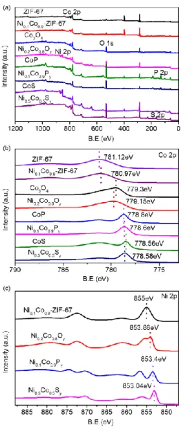
Figure 4. XPS spectra of Co-ZIF-67, Ni0.1Co0.9-ZIF-67, Co3O4, Ni0.2Co0.8Oy, CoP, Ni0.1Co0.9Py,
Co9S8 and Ni0.5Co0.5Sy catalysts in the range 100-1200 eV (a), 775-790 eV Co 2p (b), and 850-890 eV
Ni 2p(c)
While several peaks in the range of 600~1500 cm-1 are not present in the spectra of Co3O4 and
Ni0.2Co0.8Oy, and the stretching mode of C−N bonding and the aliphatic chain of the 2-MIM at 1580 cm -1 and 3135 cm-1, respectively become obscured (Fig. 4b). The C-H stretching mode of the aromatic ring
at 2929 cm-1 is present. The peaks at 661 cm-1 and 570 cm-1 corresponding to the Co-O vibration [22]
confirm that the ZIF-67 structure collapsed and Co is oxidized into Co3O4.
shown in Figure 3c. Several bands in the region of 1150 - 1000 cm-1 are assigned to the P-O vibrations of
the PO4 group [23]. While the signals associated with the C−N stretching and the aliphatic chain of 2-MIM
(1580 cm-1 and 3135 cm-1) are present in the spectra of Co9S8 and Ni0.5Co0.5Sy (Fig. 3d) indicating that
ZIF-67 structure almost collapsed after sulfuration. The new band at 617 cm-1 belongs to the Co-S bending
vibration of the Co9S8 [20b]. The peak at 1125 cm-1 is assigned to the S-O bending vibration [24], indicating
that Co is sulfured into Co9S8. The IR study confirmed that NixCo1-xOy, NixCo1-xPy and NixCo1-xSy
catalysts have been successfully synthesized.
The XPS spectra of all catalysts are shown in Fig. 4. The standard binding energy of the main peak
of cobalt species (Co 2p3/2) at 777.9 eV is present in all as-synthesized catalysts. While the Co 2p3/2 core
level region contains a main peak at 780.97 eV (Ni0.1Co0.9-ZIF-67), 779.15eV (Ni0.2Co0.8Oy), 778.6 eV
(Ni0.1Co0.9Py) and 778.56eV (Ni0.5Co0.5Sy), indicating the differences of the energy shift in the Co 2p
spectra (Fig. 4b). The as-prepared materials show higher binding energy in the Ni 2p3/2 region compared
with nickel species (852.3 eV), for instance, 855 eV for Ni0.1Co0.9-ZIF-67, 853.88eV for Ni0.2Co0.8Oy,
853.4eV for Ni0.1Co0.9Py and 853eV for Ni0.5Co0.5Sy (Fig. 4c).
The XPS spectra of NixCo1-xOy, NixCo1-xPy, and NixCo1-xSy catalysts are shown in the SI (Figs.
S5-S7). The Ni0.1Co0.9Py (Fig. S6), shows low binding energy (Co 2p1/2 and Ni 2p1/2) compared to metallic
Ni, Co, and P. The binding energies of Ni 2p and Co 2p exhibit positive shifts while P 2p is negatively
shifted which is mainly due to the partial electron transfer from Ni and Co to P.
The positive metallic (Ni and Co) and negative P centers can play a role of hydride-acceptor and proton-acceptor sites, respectively, during the electrocatalytic process [19, 25].Therefore, the positively
charged Co and Ni and the negatively charged O, P and S centers could act as hydride-acceptor and
proton-acceptor, respectively. The acceptor could promote the formation of cobalt hydride, which could
facilitate the following H2 evolution by electrochemical desorption [3b, 9a, 19, 25b, 26].
Electrocatalytic performance of NixCo1-x-ZIF-67, NixCo1-xOy, NixCo1-xPy, and NixCo1-xSy for
The electrocatalytic property of the nickel-cobalt based catalysts towards HER is evaluated. Fig.
S5 shows LSV curves in alkaline media (pH =14±0.5) for NixCo1-x-ZIF (a), NixCo1-xOy (b) ,NixCo1-xPy
(c) , NixCo1-xSy (d) at a scan rate of 10 mV s-1, respectively. It was found that at a current density of 10
mA cm-2, the catalysis showed overpotential in the following order, phosphide < oxide< sulfide < ZIF-67
in both mono-metallic and bi-metallic derivatives with specific metal ratio: CoP < Co3O4< Co9S8<
ZIF-67 and Ni0.1Co0.9Py< Ni0.2Co0.8Oy< Ni0.5Co0.5Sy< Ni0.1Co0.9-ZIF-67. The comparison of alkaline HER
activities of as-prepared catalysts with the same ratio in the precursor are listed in the supporting
information (Table S3). Obviously, the phosphide wuith the metal ratio Co: Ni = 10:0, 9:1, and 7:3 showed
the lowest overpotential at current density of 10 mA cm-2, while the others (samples Ni0.2Co0.8Oy,
Ni0.4Co0.6Oy and Ni0.5Co0.5Sy) show the lowest overpotential. The phosphide performed superior in the
high Co: Ni ratio, while the oxide and sulfide showed good performance in the middle ratio, indicating
the optimum synergistic effect of Ni and Co in samples NixCo1-xOy, NixCo1-xPy and NixCo1-xSy. The LSV,
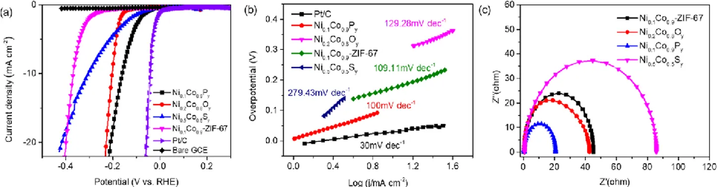
Tafel plot and Electrochemical Impedance Spectroscopy (EIS) results are shown in the Figure. 5. The Fig.
5a shows linear sweep voltammetry (LSV) curves for Ni0.1Co0.9-ZIF-67, Ni0.2Co0.8Oy, Ni0.5Co0.5Sy, and
Ni0.1Co0.9Py catalysts in alkaline media (pH =14±0.5) in comparison with bare glassy carbon electrode
(GCE) and commercial Pt/C catalyst. The Ni0.1Co0.9Py is the most active for alkaline HER with a low
overpotential of 160 mV to deliver 10 mA cm−2. As shown in Table S4, (supporting information),
compared with other as-prepared catalysts and previously reported Co-based catalysts, clearly the NixCo
1-xPy catalysts have relatively lower overpotentials at the current densities of both 10 and 20 mA cm-2.
Moreover, the Ni0.1Co0.9Py has the lowest Tafel slope of 100 mV dec-1, being smaller than that of
Ni0.1Co0.9-ZIF-67 (109.11 mV dec-1), Ni0.2Co0.8Oy (129.28 mV dec-1) and Ni0.5Co0.5Sy (279.43 mV dec-1)
catalysts (Fig. 5b). To evaluate the catalytic activities, the electrochemical impedance spectroscopy
analysis for Ni0.1Co0.9Py catalyst under the same operating conditions was conducted. For Ni0.1Co0.9
-ZIF-67, Ni0.2Co0.8Oy, Ni0.5Co0.5Sy, and Ni0.1Co0.9Py catalysts, low charge transfer resistances of 24.8, 21.0,
49.8, and 10.2 Ω, respectively are measured (Fig. 5c). In the equivalent circuit, Rs is related to the
catalytic kinetics at the catalyst/electrolyte interface, small Rct values contribute to faster charge transfer.
The sharply decreased diameter of Ni0.1Co0.9Py in the Nyquist plots of Fig. 5c suggests a much faster
electron-transfer kinetics. The Ni0.5Co0.5Sy showed the largest Rct which demonstrates the lowest
electron-transfer kinetics.
Figure 5. Polarization curves of Ni0.1Co0.9-ZIF-67, Ni0.1Co0.9Py, Ni0.2Co0.8Oy, Ni0.5Co0.5Sy, commercial
Pt/C catalyst and bare GCE measured in alkaline media (pH =14±0.5, 1 M KOH) (a) ,Tafel plots (b) and
Electrochemical Impedance Spectroscopy (EIS) Nyquist plots (c)
The following trend for the catalysts at the same current density of 10 or 20 mA cm-2 is observed:
Ni0.1Co0.9Py>Ni0.2Co0.8Oy>Ni0.5Co0.5Sy>Ni0.1Co0.9-ZIF-67. To evaluate the stability of the catalysts,
long-term electrolysis in 1.0 M KOH is carried out. The four catalysts show almost the same LSV curve with
negligible cathode current drop after 2000 cycles, which confirms their high stability for alkaline HER
(Fig. S9). To get further insight into the structure-activity correlation between HER performance and
different catalysts, a series of DFT calculations were performed (SI). For an ideal electrocatalyst, a
moderate H adsorption free energy is close to zero (ΔGH* ≈ 0), which is in favor of the adsorption and
desorption steps, thus facilitating the proton−electron-transfer process. Therefore, proton adsorption free
energy was adopted to correlate the HER performance. The results are illustrated in Fig.6 and the
optimized adsorption structures are presented in Fig. S11. We firstly compared the H adsorption free
energy of Co9S8, Co3O4 and CoP (Fig. 6a), and the H adsorption free energy of Co9S8 (1.01 eV), Co3O4
(-0.74 eV) and CoP (0.09 eV) are similar with the experimental results. Due to the lowest H adsorption
simulate the Ni1-xCoxPy (Fig. 6b), of which the ΔGH* are: Co0.7Ni0.1P (0.08197 eV), Co0.6Ni0.2P (0.09327
eV), and Co0.5Ni0.3P (0.116582 eV). As the Ni decreases, the Ni1-xCoxPy showed lower ΔGH* in the order
Co0.5Ni0.3P > Co0.6Ni0.2P > Co0.7Ni0.1P, which is in accordance with the experimental result demonstrating
that the phosphide performance is superior in the sample with high Co: Ni ratio. In conclusion, the CoP
shows superior HER performance in contrast to the Co9S8 and Co3O4. The Co0.7Ni0.1Pshows the highest
electrochemical performances according to the DFT calculations, while sample Co0.9Ni0.1Py with best
HER performance was obtained experimentally.
Figure 6. Calculated free energy diagram of the HER on the Co3O4 (110), Co9S8 (111), CoP (101)
(a), and Co0.5Ni0.3P, Co0.6Ni0.2P, CoP, Co0.7Ni0.1P (b)
The electrochemical activity of the catalysts for HER are comparable and slightly improved than
those reported in the open literature so far [11a, 18, 27]. The HER activity of Ni0.1Co0.9Py in comparison with
the materials already published are summarized in Table S4. The phosphides have high affinities for H2
and they could be suitable for HER electrocatalysis. The best performance of the Ni0.1Co0.9Py catalyst is
attributed to the following reasons: (i) the nanosized bimetallic structure provide abundant active sites for
the electrochemical reaction, (ii) Ni and Co atoms are atomically arranged in the Ni0.1Co0.9Py, (iii) the
electron transfer from Ni and Co to P improve the electron-donating ability of the catalyst, leading to the
high HER activity, (iv) DFT results further indicate that the synergistic effect between Co and Ni with
performance. Overall, the Ni0.1Co0.9Py has been considered as a highly efficient and stable electrocatalyst
for HER.
Conclusions
In summary, nanosized homeotypic bimetallic Ni1-xCoxOy, Ni1-xCoxSy and Ni1-xCoxPy catalysts were
prepared from Ni1-xCox-ZIF-67 by temperature-programmed reactions with oxygen, sublimed sulfur and
sodium hypophosphite, respectively. Compared to the monometallic Co-based materials, the homologous
bimetallic Ni1-xCox-ZIF-67, Ni1-xCoxOy, Ni1-xCoxSy and Ni1-xCoxPy catalysts exhibit better
electro-catalytic activity for hydrogen production in alkaline water electrolysis.
The high HER activity of the Ni0.1Co0.9Py modified electrode is related to the appropriate
nickel-cobalt metal ratio, high crystallinity, and nickel-nickel-cobalt synergistic accelerating electron transfer from Ni
and Co to P. This correlation between the composition and properties of nickel–cobalt nanoparticles and
their electrocatalytic performance for hydrogen evolution in alkaline media are the base for further design
of better transition metals catalyst toward the HER.
Experimental Section
Chemical and reagents
Cobalt acetate (Co(CH3CO2)2•4H2O), nickel acetate (Ni(CH3CO2)2•4H2O), 2-methylimidazole
(C4H6N2), triethylamine ((C2H5)3N), potassium hydroxide (KOH, pellets), thiourea (CH4N2S), nafion (5
wt%), ethanol (C2H6O) were purchased from Sinopharm Chemical Reagent Co., Ltd. All reagents and
solvents were used as received without further treatment.
Preparation of Co-ZIF-67: Co-ZIF-67 nanocrystals were synthesized following the procedure
described by Wang et.al. [14a] with slight modification. In a typical synthesis, solution A was prepared by
dissolving 2-methylimidazole (1.3686 g, 0.0167 mol) and TEA (1.6868 g, 0.167 mol) in 15 ml distilled
water. Both solutions were stirred with 800 r/min for 30 min. Then the two solutions were mixed in
ice-water bath for 10 min. Purple crystals were collected by centrifugation and washed several times with
distilled water and dried at 60 °C oven for 12 h. The obtained samples were denoted as Co-ZIF-67.
Preparation of NixCo1-x-ZIF-67: the cobalt acetate in the synthesis precursor was replaced with a
mixture of cobalt acetate and nickel acetate, the Co/Ni molar ratios were adjusted from 9:1 to 1:1. The
preparation of the NixCo1-x-ZIF-67 was performed in ice-water bath for 10 min. The washing and drying
procedure were same as before. The obtained samples were denoted as NixCo1-x-ZIF-67.
Synthesis of mono- and bi- metallic NixCo1-xOy, NixCo1-xSy, NixCo1-xPy catalysts
Preparation of NixCo1-xOy: the NixCo1-x-ZIF-67 samples were put into a muffle furnace and annealed
at 800 °C for 4 h under air (ramping of 2 °C min-1). The final black powder was collected at room
temperature (the samples are donated as NixCo1-xOy).
Preparation of NixCo1-xSy [20a, 20b]: NixCo1-x-ZIF-67 (0.2g) and sublimed sulfur (0.1g) were placed at
two separate positions in a porcelain boat; the sublimed sulfur was placed at the upstream side of the
furnace. The obtained samples were denoted as NixCo1-xSy.
Preparation of NixCo1-xPy[12c, 26, 28]: NixCo1-x-ZIF-67 (0.2g) and NaH2PO2•H2O (1g) were placed at
two separate positions in a porcelain boat; NaH2PO2•H2O was placed at the upstream side of the furnace.
The molar ratio of Co/P was 1:20. The obtained samples were denoted as NixCo1-xPy.
Characterization
The structure of the samples was characterized by X-ray powder diffraction (Siemens D5005 diffractometer) with Cu Kα radiation (λ=1.5418 Å) in Bragg-Brentano (θ~2θ) configuration. The
structure and morphology of the as-prepared samples were characterized by a field emission scanning
obtained using a JEM 2100 transmission electron microscope operating at 200 kV. The distribution of the
elements of the samples was measured by EDS-SEM using JEOL-7900F SEM and Oxford Instruments
X-MaxN Energy-Dispersive Spectroscopy. The hydrogen and nitrogen adsorption-desorption
experiments were performed at 77K using Quantachrome autosorb iQ3 gas sorption analyzer. The
external surface area was determined by the Brunauer-Emmett-Teller Method (BET).The infrared (IR)
spectra of samples were collected by NEXUS FT-IR using the KBr technique. Chemical composition of
the as-synthesized samples were characterized by X-ray photoelectron spectroscope with PH 5000
Versaprobe system using monochromatic Al Kα radiation (hν=1486.6 eV). Inductively Coupled Plasma
(ICP) was performed by Agilent ICPOES 720.
Electrochemical Measurements
All electrochemical measurements were carried out in nitrogen-purged 1 M KOH solution
(pH=14±0.5) at room temperature on a CHI660E electrochemical workstation using a standard
three-electrode system: a saturated calomel three-electrode (SCE) used as a reference three-electrode, a carbon rod used as
a counter electrode, and a glassy carbon electrode (GCE, 0.1256 cm2, geometric area) used as a working
electrode. The working electrode was prepared as follows. Typically, the catalytic powder (3.6 mg) and
activated carbon (0.09 mg) are added into a mixture of 1 mL ethanol and 80 μL Nafion (5 wt%) and
sonicated for 40 min to obtain a homogeneous mixture further called ink. Then (10 μL) of the catalyst ink
was deposited onto the GCE surface (loading 0.358 mg cm-2).
The polarization curves were obtained by linear voltammetry sweeping (LSV) from 0.27 V to -0.53
V (vs RHE) with a scan rate of 10 mV s-1 in 1 M KOH. Alternating current (AC) impedance measurements
were carried out at -0.3 and - 0.41 V from 100 kHz to 0.1 Hz. The stability of the catalysts was
characterized under continuous cyclic voltammetry (CV) measurements from -0.05 to 0.2 V (vs RHE) at
to eliminate dissolved oxygen. All results were calibrated with respect to the reversible hydrogen
electrode (RHE) by E (RHE) = E (V vs SCE) + 0.245 V + 0.059 pH [14a].
Theoretical calculations were performed using Vienna ab initio simulation packages (VASP) based
on density functional theory (DFT). [29] The core and valence electrons were described by the projector
augmented wave (PAW) pseudopotentials. The generalized gradient approximation (GGA) in the scheme
of proposed by Perdew, Burke, and Ernzerhof (PBE) was adopted to express the exchange correlation
interactions with a cut off energy of 400 eV.[30] A 12 Å vacuum region was used to simulate the adsorption
and all the top two layers of atoms in the structure are allowed to relax. The convergence of energy and
forces were set to 1 × 10⁻⁵ eV and 0.03 eV, respectively. The free energy of hydrogen adsorption (∆GH*)
can be calculated as follows:
∆G (H*) = ∆E + 0.24 eV
And ∆E is the adsorption energy, with defined as follows:
∆E =E (substrate + adsorbate)–Esubstrate–Eadsorbate
Acknowledgements
The authors are grateful to the National Natural Science Foundation of China [Grant No. U1862118],
funding from Thousand Talents Program, China [WQ20152100316], the Fundamental Research Funds
for the Central Universities, China [No. 18CX05018A], the State Key Laboratory of Advanced
Technology for Materials Synthesis and Processing (Wuhan University of Technology), China [No.
2018-KE-13], the Foundation Franco-Chinoise pour la Science et Applications (FFCSA), and the Sino-French LIA “Zeolite”.
Keywords: ZIF-67 • Ni-Co-doping • organized bimetallic atomic arrangement • Hydrogen evolution
reaction
ACS Catal. 2017, 7, 7126-7130.
[2] a) H. Ito, T. Maeda, A. Nakano, Y. Hasegawa, N. Yokoi, C. M. Hwang, M. Ishida, A. Kato, T.
Yoshida, Int. J. Hydrogen Energy 2010, 35, 9550-9560; b) T. Asefa, Acc. Chem. Res. 2016, 49,
1873-1883.
[3] a) X. Li, Y. Fang, X. Lin, M. Tian, X. An, Y. Fu, R. Li, J. Jin, J. Ma, J. Mater. Chem. A 2015,
3, 17392-17402; b) Y. Li, J. Liu, C. Chen, X. Zhang, J. Chen, ACS Appl. Mater. Interfaces 2017, 9, 5982-5991; c) P. Chen, K. Xu, Z. Fang, Y. Tong, J. Wu, X. Lu, X. Peng, H. Ding, C. Wu, Y. Xie, Angew. Chem. 2015, 54, 14710-14714; d) C. Guan, X. Liu, A. M. Elshahawy, H. Zhang, H. Wu,
S. J. Pennycook, J. Wang, Nanoscale Horiz. 2017, 2, 342-348.
[4] T. Ling, D. Y. Yan, H. Wang, Y. Jiao, Z. Hu, Y. Zheng, L. Zheng, J. Mao, H. Liu, X. W. Du, M.
Jaroniec, S. Z. Qiao, Nat. Commun. 2017, 8, 1509.
[5] J.-B. Raoof, S. R. Hosseini, R. Ojani, S. Mandegarzad, Energy 2015, 90, 1075-1081.
[6] T. R. Hellstern, J. D. Benck, J. Kibsgaard, C. Hahn, T. F. Jaramillo, Adv. Energy Mater. 2016, 6,
1501758.
[7] J. Yu, Q. Li, Y. Li, C.-Y. Xu, L. Zhen, V. P. Dravid, J. Wu, Adv. Funct. Mater. 2016, 26, 7644-7651.
[8] G. Anandhababu, Y. Huang, D. D. Babu, M. Wu, Y. Wang, Adv. Funct. Mater. 2018, 28, 1706120.
[9] aX. Chen, M. Cheng, D. Chen, R. Wang, ACS Appl. Mater. Interfaces 2016, 8, 3892-3900; b2013.
[10] C. Zhu, S. Fu, Q. Shi, D. Du, Y. Lin, Angew. Chem. 2017, 56, 13944-13960.
[11] a) Q. Chen, J. Miao, L. Quan, D. Cai, H. Zhan, Nanoscale 2018, 10, 4051-4060; b) Z. Peng, D.
Jia, J. Tang, Y. Wang, Y. Wang, L. Zhang, G. Zheng, J. Mater. Chem. A 2014, 2, 10904; c) J. Yao,
P. Xiao, Y. Zhang, M. Zhan, F. Yang, X. Meng, J. Alloys Compd. 2014, 583, 366-371.
[12] a) P. He, X.-Y. Yu, X. W. Lou, Angew. Chem. 2017, 129, 3955-3958; b) Y. Zhao, G. Fan, L. Yang,
Y. Lin, F. Li, Nanoscale 2018, 10, 13555-13564; c) X. Liang, B. Zheng, L. Chen, J. Zhang, Z.
Zhuang, B. Chen, ACS Appl. Mater. Interfaces 2017, 9, 23222-23229.
[13] Y. Lü, W. Zhan, Y. He, Y. Wang, X. Kong, Q. Kuang, Z. Xie, L. Zheng, ACS Appl. Mater. Interfaces
[14] a) M. Wang, X. Jiang, J. Liu, H. Guo, C. Liu, Electrochim. Acta 2015, 182, 613-620; b) J. Zhou,
Y. Dou, A. Zhou, R.-M. Guo, M.-J. Zhao, J.-R. Li, Adv. Energy Mater. 2017, 7, 1602643.
[15] S. Ding, Q. Yan, H. Jiang, Z. Zhong, R. Chen, W. Xing, Chem. Eng. J. 2016, 296, 146-153.
[16] F. Bai, Y. Xia, B. Chen, H. Su, Y. Zhu, Carbon 2014, 79, 213-226.
[17] X. Yang, J. Chen, Y. Chen, P. Feng, H. Lai, J. Li, X. Luo, Nano-micro Lett. 2018, 10, 15.
[18] T. Gholami, M. Salavati-Niasari, S. Varshoy, Int. J. Hydrogen Energy 2017, 42, 5235-5245.
[19] A. M. Pornea, M. W. Abebe, H. Kim, Chem. Phys. 2019, 516, 152-159.
[20] a) J. He, Y. Chen, A. Manthiram, Energy Environ. Sci. 2018, 11, 2560-2568; b) J. Huang, X. Tang,
K. Liu, Z. Li, Mater. Lett. 2018, 210, 88-91; c) J. Yang, G. Zhu, Y. Liu, J. Xia, Z. Ji, X. Shen, S.
Wu, Adv. Funct. Mater. 2016, 26, 4712-4721.
[21] K.-Y. A. Lin, H.-A. Chang, J. Taiwan Inst. Chem. Eng. 2015, 53, 40-45.
[22] C.-W. Tang, C.-B. Wang, S.-H. Chien, Thermochim. Acta 2008, 473, 68-73.
[23] J. Li, G. Wei, Y. Zhu, Y. Xi, X. Pan, Y. Ji, I. V. Zatovsky, W. Han, J. Mater. Chem. A 2017, 5,
14828-14837.
[24] J. Wang, L. Li, X. Chen, Y. Lu, W. Yang, J. Mater. Chem. A 2016, 4, 11342-11350.
[25] a) I. S. Amiinu, Z. Pu, X. Liu, K. A. Owusu, H. G. R. Monestel, F. O. Boakye, H. Zhang, S. Mu,
Adv. Funct. Mater. 2017, 27, 1702300; b) R. Wang, L. Wang, W. Zhou, Y. Chen, H. Yan, Z. Ren,
C. Tian, K. Shi, H. Fu, ACS Appl. Mater. Interfaces 2018, 10, 9999-10010; c) X. R. Wang, J. Y.
Liu, Z. W. Liu, W. C. Wang, J. Luo, X. P. Han, X. W. Du, S. Z. Qiao, J. Yang, Adv. mater. 2018,
30, e1800005.
[26] M. Liu, J. Li, ACS Appl. Mater. Interfaces 2016, 8, 2158-2165.
[27] a) J. D. Benck, T. R. Hellstern, J. Kibsgaard, P. Chakthranont, T. F. Jaramillo, ACS Catal. 2014, 4,
3957-3971; b) L. Chen, J. W. Ye, H. P. Wang, M. Pan, S. Y. Yin, Z. W. Wei, L. Y. Zhang, K. Wu,
Y. N. Fan, C. Y. Su, Nat. Commun. 2017, 8, 15985; c) S. Dou, X. Li, L. Tao, J. Huo, S. Wang,
Chem. Commun. 2016, 52, 9727-9730; d) B. Y. Guan, L. Yu, X. W. D. Lou, Adv. Sci. 2017, 4,
Z. Liu, K. P. Loh, Adv. Funct. Mater. 2013, 23, 5363-5372.
[28] a) P. Jiang, Q. Liu, C. Ge, W. Cui, Z. Pu, A. M. Asiri, X. Sun, J. Mater. Chem. A 2014, 2, 14634;
b) Y. Li, H. Zhang, M. Jiang, Y. Kuang, X. Sun, X. Duan, Nano Res. 2016, 9, 2251-2259.
[29] a) G. Kresse, J. Furthmüller, Comput. Mater. Sci. 1996, 6, 15-50; b) G. Kresse, J. Furthmüller,
Phys. Rev. B 1996, 54, 11169-11186.
[30] a) G. Kresse, D. Joubert, Phys. Rev. B 1999, 59, 1758-1775; b) P. E. Blöchl, Phys. Rev. B 1994,