Integrated Management of Interface Power (IMIP)
Framework
Par
Hicham Mahkoum
Département d’informatique et de recherche opérationnelle Faculté des arts et des sciences
Mémoire présenté a la Faculté des arts et des sciences en vue de l’obtention du grade de
Maîtrise ès sciences (M.Sc.) en Informatique
Décembre, 2009
Faculté des arts et des sciences
Ce mémoire intitulé:
Integrated Management of Interface Power (IMIP) Framework
Présenté par : Hicham Mahkoum
a été évalué par un jury composé des personnes suivantes :
El Mostapha Aboulhamid, président-rapporteur Abdelhakim Hafid, directeur de recherche
Behcet Sarikaya, codirecteur Stefan Monnier, membre du jury
Résumé
La présence importante de plusieurs réseaux sans-fils de différentes portées a encouragée le développement d’une nouvelle génération d’équipements portables sans-fils avec plusieurs interfaces radio. Ainsi, les utilisateurs peuvent bénéficier d’une large possibilité de connectivité aux réseaux sans-fils (e.g. Wi-Fi [1], WiMAX [2], 3G [3]) disponibles autour. Cependant, la batterie d’un nœud mobile à plusieurs interfaces sera rapidement épuisée et le temps d’utilisation de l’équipement sera réduit aussi. Pour prolonger l’utilisation du mobile les standards, des réseaux sans-fils, on définie (individuellement) plusieurs états (émission, réception, sleep, idle, etc.); quand une interface radio n’est pas en mode émission/réception il est en mode sleep/idle où la consommation est très faible, comparée aux modes émission/réception. Pourtant, en cas d’équipement portable à multi-interfaces radio, l’énergie totale consommée par les interfaces en mode idle est très importante. Autrement, un équipement portable équipé de plusieurs interfaces radio augmente sa capacité de connectivité mais réduit sa longévité d’utilisation.
Pour surpasser cet inconvénient on propose une plate-forme, qu'on appelle IMIP (Integrated Management of Interface Power), basée sur l’extension du standard MIH (Media Independent Handover) IEEE 802.21 [4]. IMIP permet une meilleure gestion d’énergie des interfaces radio, d’un équipement mobile à multi-radio, lorsque celles-ci entrent en mode idle.
Les expérimentations que nous avons exécutées montrent que l’utilisation de IMIP permet d'économiser jusqu'a 80% de l'énergie consommée en comparaison avec les standards existants. En effet, IMIP permet de prolonger la durée d'utilisation d'équipements à plusieurs interfaces grâce à sa gestion efficace de l'énergie.
Mots Clés: MIH (Media Independent Handover), Proxy, Proxied Interface, Energie Consommé, Mise-a-jour de localisation, mode Idle
Abstract
The large availability of wireless networks of different ranges, has contributed to the development of new generation of handheld devices with multi-radio interfaces. Thus, the end-users are able to achieve ubiquitous and seamless connectivity across heterogeneous wireless networks (e.g., Wi-Fi [1], WiMAX [2] and 3G_LTE [3]). However, a mobile node with multi-radio interfaces has its battery energy consumed rapidly, which reduces the operation/usage time of the device. To improve battery usage, wireless network standards have defined (individually) different interface states (transmit, receive, idle, sleep, etc.); when an interface is not transmitting or receiving, it goes to sleep/idle state where energy consumption is very low compared to transmit and receive states. However, in the case of multi-radio handheld devices, the total energy consumed by the interfaces in sleep/idle state is significant. Thus, equipping a mobile device with multiple interfaces increases its seamless connectivity but reduces its operation/usage longevity.
To overcome this inconvenient, we proposed a framework, called IMIP (Integrated Management of Interface Power) that consists of an extension of MIH (Media Independent Handover) IEEE 802.21 standard [4]. IMIP allows a better power management of radio interfaces of a multi-radio mobile node; indeed, it reduces considerably energy consumption. The basic idea behind IMIP is to shut down any interface in idle mode and use a proxy that emulates the interface; the proxy wakes up the interface when it receives a connection request directed to this interface. IMIP requires at least one interface in active mode. Experiments show that using IMIP enables a saving of up to 80% of power consumption compared with existing power management standards. Thus, IMIP allows longer usage of multiple interface devices thanks to its effective energy management.
Keywords: MIH (Media Independent Handover), Proxy, Proxied Interface, Energy Consumption, Location Update, Idle mode
Table of Contents
Résumé ... iii
Abstract ... iv
Table of Contents ... v
List of tables ... viii
Table of figures ... ix
List of acronyms and abbreviations ... xi
Accord des coauteurs ... xiii
Dedication ... xiv
Remerciements ... xv
Chapter 1 ... 8
Introduction ... 8
1.1 Multi-Radio Interface Device ... 8
1.2 Energy consumption issue ... 9
1.3 Motivation ... 10 1.4 Contributions ... 11 1.5 Organization of thesis ... 12 Chapter 2 ... 13 Literature Review ... 13 2.1. Network Standards ... 13 2.1.1 WiMAX Technology ... 13
2.1.3 Media Independent Handover ... 19
2.2 Key related Contributions ... 25
2.1.1. Hybrid location-Update Scheme ... 25
2.1.2 Autonomic Group Location Update for Mobile Networks ... 27
2.1.3 CoolSpots: reducing the power consumption of wireless mobile devices with multiple radio interfaces ... 29
2.1.4 Wake-on-wireless: An event driven energy saving strategy for battery operated
devices ... 31
2.1.5 Cell2Notify: Wireless wakeups revisited: Energy management for VoIP over Wi-Fi smartphones ... 32
2.2. Analysis ... 34
Chapter 3 ... 38
A Framework for Power Management of Handheld Devices with Multiple Radios ... 38
Context ... 38
Abstract ... 39
I. Introduction ... 40
II. Energy Saving Framework ... 42
A. MIH Services ... 43
B. Idle Mode in WiMAX and LTE Networks ... 44
C. Multi-radio mobile node architecture... 45
D. Model of Communication ... 46
III. Mechanisms ... 48
A. MIH Extensions ... 48
B. Idle mode entry mechanism ... 49
C. Waking-up mechanism ... 50
IV. Analysis ... 53
V. Conclusion ... 55
References ... 55
Chapter 4 ... 57
Proxying Location Update for Idle Mode Interfaces ... 57
Context ... 57
Abstract ... 58
I. Introduction ... 58
B. Location update in WiMAX ... 61
C. Tracking area update in LTE ... 62
III. Proxying Location Update ... 63
A. Proxying radio interface ... 63
B. Techniques for proxying LU ... 63
IV. DESIGN of IMIP FRAMEWORK FOR LU ... 69
A. Wrapper Entity on MME ... 69
B. Wrapper Entity on PC ... 70
C. IS and CS primitives extension ... 71
D. Extension of IS database ... 72 V. Analysis ... 73 A. Energy consumption ... 73 VI. Conclusion ... 76 References ... 77 Chapter 5 ... 79
Conclusion and perspectives ... 79
5.1. Conclusion ... 79
List of tables
Chapter 1
Table 1: The power of radio interfaces for different modes. ... 10
Chapter 2
Table 1: Comparing power consumption of Wi-Fi and Bluetooth radio interfaces on different states. ... 30 Table 2: Metric-based comparison of representative energy management contributions .... 36
Chapter 3
Table I. Command Service primitives’ extension ... 48 Table II. Event Service primitives’ extension ... 48 Table III. POWER CONSUMPTION OF WLAN AND 3G INTERFACES ... 53
Chapter 4
Table 1. Proposed MIH CS and IS primitives for proxying LU procedure ... 72 Table 2. Values of the parameters used in the evaluation ... 74 Table 3. Power consumption values of wireless interfaces in different modes ... 74
Table of figures
Chapter 1
Figure 1: Circuit card with 3 fully integrated radio technologies [21] ... 8
Figure 2: Example of inter-technology handover from Wi-Fi, WiMAX than 3GPP network. ... 9
Chapter 2 Figure 1: A mobile node moving from one paging area to another. ... 15
Figure 2: Case scenario of handover in a heterogenous envirement (from Wi-Fi to WiMAX network). ... 22
Figure 3: Simplified sequence diagram of case scenario of a handover from Wi-Fi to WiMAX network. ... 24
Figure 4: Frequency of location updates between two calls in hybrid scheme [12] ... 26
Figure 5: Typical scenario of group location update ... 28
Figure 6: In idle state the Wi-Fi interface consumes approximately 70% of the total power ... 29
Figure 7: CoolSpots model consists of radio interface switching. ... 30
Figure 1: Comparing standby lifetime of a Motorola V60t (cell phone) with an IEEE 802.11b card in PS/CAM modes [18] ………... 31
Figure 9: Comparing power consumption of three radio interfaces (2 Cellular and Wi-Fi) in three modes ……… . 33
Chapter 3 Figure 1. MIH layers, services and services access points (SAPs) ... 43
Figure 2. Multi-radio proxy architecture ... 45
Figure 3. MN Initiated idle mode and proxied mode entry ... 47
Figure 4. Waking-Up a proxied interface ... 52
Chapter 4
Figure 1. Architecture for proxing interfaces of multi-radio interfaces ... 61
Figure 2. LU procedure performed by the Proxy with PC/MME ... 65
Figure 3. Geo-position based LU without PC/MME relocation ... 68
Figure 4. Proxy Design on MME ... 70
Figure 5. Proxy Design on Anchor PC ... 71
Figure 6. Energy saving when proxying (a) WiMAX, (b) 3G idle interface without considering MN ... 76
List of acronyms and abbreviations
Acronyme Description
AP Access Point
BS Base Station
DHCP Dynamic Host Configuration Protocol
DNS Domain Name System
eNB Evolved NodeB
GPS Global Positioning System
IMIP Integrated Management of Interface Power
IS Information Server
LU Location Update
LTE Long Term Evolution
MICS Media Independant Command Service MIES Media Independant Event Service MIH Media Independant Handover
MIIS Media Independant Information Service MME Mobility Management Entity
NSE Network Selection Entity
MN Mobile Node
SIP Session Initiation Protocol
PA Paging Agent
PC Paging Controller
PoA Point of Attachement
PoS Point of Service
WLAN Wireless Local Access Network
WMAN Wireless Metropolitan Access Network WWAN Wireless Wide Access Network
Dedication
To my wife. To my parents. To my family. To my family in law.
Remerciements
Je tiens tout d’abord à adresser mes remerciements et ma gratitude à mon directeur et mon codirecteur de recherche, les professeurs Abdelhakim Hafid et Behcet Sarikaya pour leur patience, leur disponibilité, leur aide et leur support tout au long de ce travail.
J’aimerais remercier ma femme Imane pour sa présence et son soutien permanent. Enfin, que tous celles et ceux qui m’ont apportés leur appui trouvent ici l’expression de mes sincères remerciements
Chapter 1
Introduction
1.1 Multi-Radio Interface Device
Nowadays more multi-radio networks coexist with radios operating on adjacent and overlapping frequency bands. This coexistence has encouraged manufacturers to integrate multi-radio interfaces in one handheld device. This became possible thanks to integrated digital CMOS (Complementary Metal–Oxide–Semiconductor) processes and digital circuits. Fig. 1 shows an example of circuit card [21] containing two chips, ‘W2CBWG01’ and ‘W2CBWG03’, which are fully integrated 802.11b/g WLAN, Bluetooth and GPS solutions designed specifically for ultra-mobile portable electronics.
The new generation of handheld devices, for example iPhone (apple), are now equipped with 3G, Wi-Fi, Bluetooth and GPS radio interfaces. The new generation of iPhone will be equipped also with WiMAX [2] interfaces too. This allows seamless connectivity to the iPhone user, as illustrated in Fig. 2. The user is then able to use the same device, his iPhone, to connect to the local network (WLAN) in his work place or home and establish an internet connection. When leaving his work place or home, he doesn’t need to
reestablish the internet connection using WiMAX interface; he could seamlessly continue
using his internet connection while moving his radio connection to WiMAX network. If the user moves from WiMAX radio area coverage, he could switch again seamlessly to 3G
network and keep using the same internet connection. Obviously, this seamless handover procedure from one radio network to another is possible if the mobility over heterogeneous networks is supported by the network (see MIH IEEE 208.21 [4]).
1.2 Energy consumption issue
Multi-radio handheld devices have limited battery life time. According to [12] and [5] the radio interfaces in a PDA are the main source of energy consumption. A device equipped with multiple radio interfaces has its battery life decreasing rapidly. This is due to energy consumption of each radio interface even if they are not used for transmitting or receiving effective data. When an interface is transmitting, the energy consumption is the highest; lower when receiving and the lowest when in idle/sleep state. According to [12], [6] and [8], energy consumption of radio interfaces (Wi-Fi, WiMAX and 3G) in different states (transmitting, receiving and idle) is presented in Table 1.
Table 1: The power of radio interfaces for different modes.
Mode Wi-Fi WiMAX 3G
Tx(mW) 890 530 1100
Rx(mW) 690 510 555
Idle(mW) 256 80 19
The idle state is defined individually by each network standard. In general, it allows energy consumption reduction when the interface is not used (transmitting/receiving). However, when we put together the power consumption of the multi-radio interfaces in idle state, the consumed power energy is considerable. This is due to the fact that each interface in idle state is managed individually according to (or by) its defined standard.
1.3 Motivation
Energy consumption becomes a critical issue for devices with multi-radio interfaces. Power management has been already addressed by the different wireless network technologies/standards; however, it is considered from single radio interface point of view. We propose to use these solutions, however, from global point of view; indeed, we propose an integrated power management that proxy (and shut down) interfaces in idle mode and makes use of only one active interface. Our proposed approach enables considerable energy savings (see Chapters 3-4 [10, 11]) and it is based on MIH (IEEE 802.21) [4] which is a standard that allows seamless handover from one wireless network technology to another. This seamlessness is realized by a number of services (Command, Event and Information) and primitives defined in IEEE 802.21. It was easy choice for us to consider using IEEE 802.21 as a baseline to define our proposed approach. Indeed, most of service and primitives defined in IEEE 802.21 can be used to realize our approach; thus, we defined new primitives and extended functionalities, as an extension of MIH, called EMIH (Enhanced MIH) to implement our proposed integrated power management.
1.4 Contributions
In this project, we propose a solution for the energy consumption issue, called IMIP (Integrated Management of Interface Power). It consists of proxying idle radio interfaces, of a multi-radio device, when in idle mode. When proxied, the idle interfaces are turned off which allows considerable energy saving. Our contributions can be summarized as follows:
• In the first contribution [10], we proposed two sets of mechanisms that allow the management of idle radio interfaces. The first mechanism defines the procedures to be performed when an interface enters idle mode. The second mechanism defines the procedure to wake up an idle interface after being proxied. It is important to emphasize that during the idle/proxied period, the network believes that the interface is in idle mode; this way the assigned resources (to the corresponding mobile device), by the network, will stay maintained. When the proxied interface is powered-off, to ensure the communication between the MN (Mobile Node) and the network (of the proxied interface) we propose to use the active interface; we assume that a single radio interface is always active to maintain an IP session with the proxies(s) in the network(s). Thus, during the proxing period the communication between the mobile and the network is made through the active interface.
• In the second contribution [11], we propose another proxying mechanism “Proxying Location Update”. The idle interface has to perform a location update to inform the network about its current location. The location procedure is performed either periodically or following location (paging/tracking area) change. This requires that the idle interface has to become available periodically to perform a location update and to check its current location; if it is in a new location it has to perform a location update. This situation is a source of energy consumption which could be saved/reduced if the proxy entity [10] (defined in the first contribution) performs the location update procedure instead of the idle interface. We identified two possible ways to proxy the location update: (1) the MN mobility is not considered and only
the periodic location update is proxied. In this case, the network believes that the mobile didn’t change the location even if it does; and (2) the periodic location update procedure is proxied and the MN mobility is considered; the MN is able to determine its position (e.g., based GPS). In this case, the mobile checks periodically its geographic location and decides whether a location update should be performed or not
• If the response is yes, the proxied interface will be waken-up to perform a location update to inform the network about its new location.
This thesis is presented as 2 papers format. The first paper [10], "A Framework for
Power Management of Handheld Devices with Multiple Radios", was published in IEEE
WCNC 2009 and the second paper, "Proxying Location Update for Idle Mode Interfaces" was accepted in IWCMC 2010, [11].
1.5 Organization of thesis
The rest of this thesis is organized as follows. Chapter 2 presents related work. Chapter 3 consists of the paper “A Framework for Power Management of Handheld
Devices with Multiple Radios” [10]. Chapter 4 consists of the paper “Proxying Location Update for Idle Mode Interfaces” [11]. Chapter 5 concludes the thesis and presents future
Chapter 2
Literature Review
In this chapter, we present an overview of wireless network standards and literature related to our research project. More specifically, we present idle mode and location update mechanisms, as defined in WiMAX/IEEE 802.16 [2] and 3G LTE (third Generation Long Term Evolution) [3] standards and the network entities directly concerned with these mechanisms. We also present the handover mechanism as defined in MIH standard [4] and the network entities supporting this mechanism. Then, we present the key contributions that aim to increase energy savings in wireless devices. We conclude by presenting a critical analysis of these contributions; this analysis gives the rationale behind our contributions in this thesis.
2.1. Network Standards
This section aims to provide an overview of idle mode as a mechanism to achieve a power saving and location update (in idle mode) as a mechanism for tracking the location of MNs. The network entities, PC/MME (Paging Controller/Mobility Management Entity) supporting these mechanisms in WiMAX/3G LTE systems, are briefly presented. This section also provides a brief description of paging/tracking areas used in the schemes that support both idle mode and location update mechanisms.
In this section, we also briefly introduce MIH standard, more specifically MIH services, IS server entities and a scenario describing a handover procedure,
2.1.1 WiMAX Technology
WiMAX is WMAN (Wireless Metropolitan Area Network) technology, also known as IEEE 802.16 [25], which provides up to 10 Mbps broadband wireless access within a range of up to 50/15 km for fixed/mobile nodes and designed to operate in 2-11 GHz
frequency range. WiMAX technology, already, considered as a leading technology for next-generation mobile broadband, intends also to satisfy the requirements of 4G1 standards.
Power saving is one of the key features supported by WiMAX standard; it helps reducing the power consumption of MNs (equipped with a WiMAX interface) not in active mode. To realize this feature, WiMAX defines; (1) Idle mode as a low power state; (2) location update as a procedure to update the system about the current location of the MN; and (3) paging area as a way of grouping base stations. WiMAX has also defined PC (Paging Controller) entity that manages the idle MNs located in paging area(s) that under its (PC) management. The idle MNs need to perform the location update procedure to update the PC about their new/current locations.
Before briefly describing the idle mode and location update in WiMAX networks, we define paging area and paging controller.
Paging Area
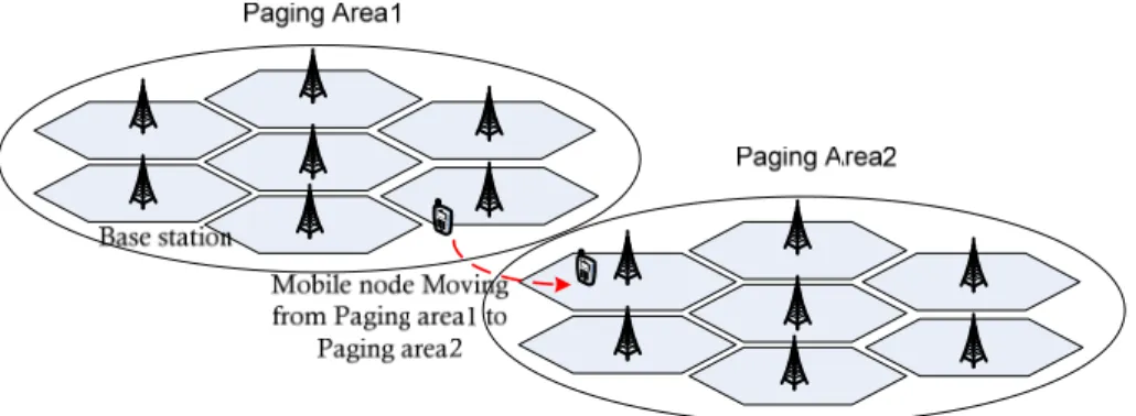
Base stations are divided (grouped) into logical groups called paging areas. They (paging areas) form a contiguous geographic coverage region where the MN does not need to transmit in the upper-link (communication from the user to the system), and can be paged in the downlink (communication from the system to the user) if there is traffic coming for it. The size of the paging areas should be designed large enough in such that the MN will remain within the same paging group most of the time, and small enough that the paging overhead is reasonable. Fig. 1 shows an example of a MN moving from one paging area to another.
1 Refer to fourth generation of cellular wireless standards. Unlike earlier wireless standards (e.g. 2G, 3G), their
Figure 2: A mobile node moving from one paging area to another.
Paging Controller
PC (Paging Controller) is a functional entity that manages the activity of idle MNs in the network. The WiMAX standard [1] requires that each idle MN should be managed by a single PC (anchor PC). The latter manages and maintains the location information, of idle MNs located in the paging area(s) under its management, up to date. The location information maintained in the system is in fact, stored in an LR (Location Register) entity. WiMAX also defined relays PCs (non-anchor PCs) which participates in relaying paging and location management messages (from/to anchor PC). For different reasons (e.g. mobility) the idle MN could be assigned a new (different) anchor PC; this is referred to as PC relocation. The relocation happens mainly during the location update procedure.
Idle Mode
To reduce the power consumption of MNs and allow them to operate for a longer duration, WiMAX/IEEE 802.16 standards define two power-saving modes: (1) sleep mode; and (2) idle mode. When the MN has no traffic (not transmitting/receiving), it switches either to sleep mode or idle mode as the power consumption is lower in these modes. In both modes, the MN radio interface is powered off (in a controlled manner) and becomes occasionally available to receive calls from the network. Unlike in sleep mode, where the
MN has to keep registered with the serving base station and has to perform a handoff2 procedure if necessary, in idle mode the MN has not. This allows it to achieve greater power saving [25].
However, even when not registered with any base station, the idle MN (with the interface in idle mode) still receives downlink broadcasted traffic. The MN exits idle mode (wakes-up) when it receives an indication of down link traffic from the system. To exit idle mode, the system sends a paging message (paging procedure [1]) to all base stations forming the paging area where the idle MN is believed to be currently located (last reported paging area).
Once the MN is paged and exits idle mode, it goes to active mode to handle the received call. Note that the MN (in idle mode) is also required to wake up periodically (for a listening period) to update its stored paging area identification and report it to the network if necessary (see location update mechanism below).
Location Update
When entering idle mode the MN is assigned a PC that manages the serving base station and the paging area it belongs to. The mobility management of idle MNs is based on the location update procedure. For the PC to track the location (paging area identification) of a managed idle MN, the MN should report its current location periodically and after each paging area change. The idle MN uses the location update procedure to report to its managing PC its current location. The PC could also initiate (request) a location-update procedure to update the maintained location information in the system. This location information helps the paging system to locate and page the idle MN efficiently (in terms of response time and deployed resources).
2.1.2 LTE Technology
LTE (Long Term Evolution) is the next generation of mobile telecommunication networks and the last toward the 4G cellular networks. The LTE project is based on a set of enhancements to the existing UMTS (Universal Mobile Telecommunications System) technology and aims to comply with IMT-Advanced (International Mobile
Telephony-Advanced) 4G [29] requirements. LTE is also considered as new generation of WWAN
(Wireless Wide Area Network) technology; it is required (designed) to provide up to 100 Mbps for downlink and 50 Mbps for uplink with a radio latency of 10 ms. The LTE coverage range expected to go from 5 Km (full performance) to 100 Km (operational).
LTE specifications also addressed a set of power management requirements including idle mode [26] to reduce the power consumption of the MN when it is not active. In LTE systems, it is the MME (Mobility Management Entity) that manages the mobility of the MN in both modes: active and idle. The MME is also responsible for paging the idle MN when downlink traffic is received. The base stations, called eNB (evolved NodeB) in LTE system, are also grouped in what is called Tracking Areas. To page an idle MN, MME sends a paging message to the tracking area reported (by the MN) during the last tracking area update (procedure).
Before briefly describing the idle mode and location update in LTE networks, we define tracking area and mobility management entity.
Tracking Area (TA)
A tracking area model, in LTE system, is similar to paging area defined in WiMAX. A tracking area is a logical grouping of cells (eNBs) that helps to represent and manage the locations of MNs at higher level. It is important to note that LTE network management considers dynamic re-configuration of the TA(s) based on collected network statistics and monitored performance indicators. Note also that a MN could be assigned multiple tracking areas (in his TAL - Tracking Area List) to avoid unnecessary Tracking Area Updates
Mobility Management Entity (MME)
MME is the network entity that manages and stores MN contexts, generates temporary identities and allocates them to the MN. It is the key access-control network in LTE systems; it checks the authorization of MN to camp on the TA. It is also responsible for idle MN mobility management including tracking its location and performing paging procedure when needed.
Idle Mode
Unlike in active mode, where the MN is in full power mode and its location is determined at cell level, in idle mode, the MN is in power-conservation mode and does not inform the network of each cell change [25]. LTE system needs to track the location of idle MN to the granularity of a tracking area. In fact, idle MN maintains a list of tracking areas, sent by MME during idle mode entry, where the MN can traverse without updating the MME (by performing a tracking area update). To wake-up an idle MN, the MME pages it in the last reported tracking area list.
Tracking Area Update (TAU)
Unlike in WiMAX system, where the MN performs location update with the PC only in idle mode, in LTE systems, the MN may perform a TAU (Tracking Area Update) [30] with its managing MME, in both active and idle mode.
In LTE systems [4], a MN entering the network is assigned a TAL. The MN does not need to perform a TAU as long it is moving within these TAs. When the MN enters a new TA, not in the assigned list (TAL), it has to perform TAU with its MME. Note that if the new entered TA is managed by a different MME, the management of the MN is then relocated to the new MME; this is done during TAU with MME relocation. After performing a TAU, the TAL maintained in the system is updated with the one stored in the MN. The TAU is always initiated by the MN.
The TAU procedure could be also triggered when [30]; (1) a periodic TAU timer has expired; (2) a change of MN capabilities (e.g. radio, network, etc...); and (3) a change in the network configuration (e.g. caused by a load balancing of eNBs, dynamic reconfiguration of the network).
2.1.3 Media Independent Handover
MIH (Media Independent Handover) or IEEE 802.21 is a standard developed to enable mobile devices to seamlessly handover between different types of network technologies (e.g. moving from 802.11 network to 802.16). The handover procedure is composed of three steps:
1. Initiation: This step corresponds to the situation where the mobile device needs to move to another network (e.g. because the current radio link is going down or does not satisfy the application requirements). During this step all the available links in the mobile device neighborhood are discovered and pre-selected for handover.
2. Preparation: In this step, the resources in the future serving network are checked and reserved. The MN is then committed to handover to this network and sets up radio-link layer connection and IP connectivity with this one (called handover commit).
3. Execution: After link setup, with the new network, the mobile device starts handover signaling exchange, context transfer and finally data packet transfer and reception with the new network (also called handover compete).
To perform handover, the mobile device relies on network MIH functional entity called PoS (Point of Service) which could be collocated with AP (Access Point). Note that MIH standard scope mainly focuses on the first two presented steps. The third step, handover execution, is not considered within the scope of MIH. The next sections are brief
presentations of the MIH services, IS (Information Server) and a case scenario illustrating a handover from one network technology to another one.
MIH Services
The communication between the MIH entities makes use of the MIHF (Media Independent Handover Function) layer located between layer 2 (wireless technology) and layer 3 (IP layer). The MIH messages are exchanged between different entities and different layers; they go through the MIHF layer. The exchanged MIH messages are of three types: event, command and information. MIHF layer is composed of three services that generate and handle these messages:
1- MIES (Media Independent Event Service): This service handles the event messages used to indicate the link or physical layer state changes in real time. The events may concern local or remote link/physical layer and are reported to the upper layer to be considered for any decision making. Event messages flow is always from lower layers to upper ones.
2- MICS (Media Independent Command Service): This service handles the command messages generated by higher layers (e.g. as reaction to a received event). The command message may convey a user decision to switch from one radio interface to another. They could concern local or remote decisions and their flow is always from upper layers to lower ones.
3- MIIS (Media Independent Information Service): This service handles the information messages that concerns mainly heterogeneous networks. This information, stored in MIH entity called IS (Information Server), concern mainly the resources of networks (candidates for a handover) in the mobile device neighborhood. This helps MN to achieve a seamless wireless handover. The flow of information messages is either from upper to lower layers or opposite.
Information Server (IS)
Information server is the MIH entity where the heterogeneous information concerning available neighboring networks is maintained; it could be requested by other MIH entities, particularly a MN detecting a handover condition. More specifically, the IS maintains, in its database, a list of available networks (e.g. 802.11/16, GSM, UMTS, LTE etc…), link layer information, higher layer services, operator costs or even vendor specific information. All this information could be requested and used for discovery and selection of networks during a handover.
Handover Scenario
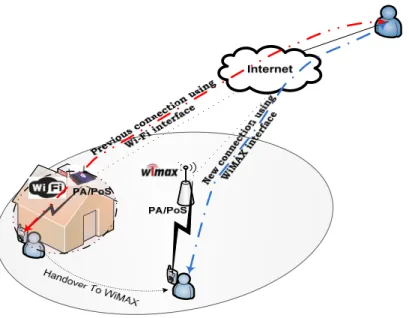
In this case, we provide an overview of a handover in a heterogeneous environment, more specifically from Wi-Fi to WiMAX network, illustrating the MIH operations. Fig. 2 shows a user in communication with another one, using Wi-Fi network connection at home. When he starts leaving the house (getting away from Wi-Fi network), his Wi-Fi connection starts going down; thus, he switches to another available wireless network (WiMAX in this scenario). This network switching (handover) takes place without stopping or interrupting the user conversation (communication).
Figure 3: Case scenario of handover in a heterogenous envirement (from Wi-Fi to WiMAX network).
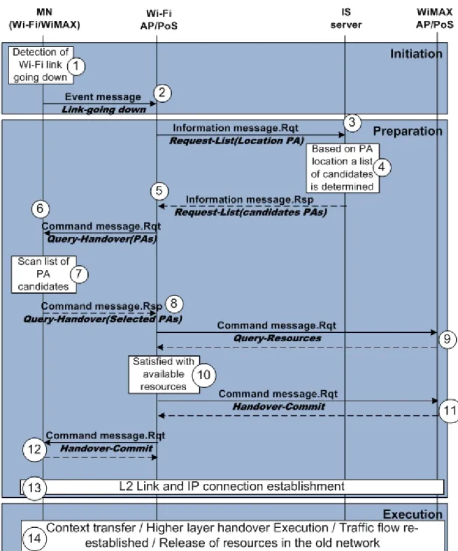
Fig. 3 describes the interactions between the MN and other MIH entities (PoS and IS) that took place in the scenario shown in Fig. 2. These interactions to initiate, prepare and execute the handover from WiFi network to WiMAX network, are as follows:
1- After leaving the house, the MN detects degradation in the radio signal strength received from Wi-Fi serving AP.
2- The MN then uses MIH Event Notification Service to inform the MIHF layer in the Wi-Fi/PoS about the link going down.
3- To prepare for a handover, the Wi-Fi/PoS sends a MIH Information message to the IS requesting the list of the APs (of different networks) in its location.
4- The IS processes and determines a list of candidate APs that are located near the requesting Wi-Fi/PoS.
5- The IS response contains the list of APs candidates for a handover.
6- The Wi-Fi/PoS sends a MIH Command message requesting it to scan the list of candidate APs.
7- The MN uses the received list of candidate PAs (Point of Attachments), performs a radio scan and makes a selection based on the results of the radios scan.
8- The selected PAs are sent back to the Wi-Fi/PoS as a response.
9- The Wi-Fi/PoS sends a Command request asking for the available resources in the selected networks (APs). Only the case of WiMAX is shown here.
10- After processing the response, the Wi-Fi/PoS selects the AP (in this case WiMAX/PoS network) with sufficient available resources.
11- After selecting WiMAX as the new network for the handover, the Wi-Fi/PoS sends a MIH Command, to commit to handover, to the WiMAX network.
12- The Wi-Fi/PoS informs and requests the MN to commit to handover with WiMAX/PoS entity.
13- The MN establishes radio link and IP connection with WiMAX network.
14- At this stage, the handover preparation is achieved, the handover execution is made. This includes MN context transfer to WiMAX network, higher layer handover and traffic flow re-establishment. This step also includes the release of the resources that were used by the MN in the old network (Wi-Fi).
2.2 Key related Contributions
In this Section, we present briefly the most related contributions to our research in this thesis.
2.1.1. Hybrid location-Update Scheme
The hybrid location-update scheme [12] is an approach which combines two approaches (time-based and movement-based) that an MN uses to update the network concerning his location.
Time-based approach consists of updating periodically (every T time-unit) the system about the mobile location and movement-based approach consists of updating the system about the mobile location each time the mobile has crossed N cell-boundaries. The key issue with these approaches is that they may update the system too or less frequently than needed. This may cause either (1) waste of resources (including MN energy) when unnecessary location updates are processed; or (2) non-accuracy of the MN current location; this may introduce considerable delay to locate the MN upon receipt of a call directed to the MN.
With the objective to reduce energy consumption, the authors [12] propose a scheme to compute “optimal” values for T (time between two location-updates) and N (number of crossed cells).
First they define the total update period
𝑇 + 𝑚 (1)
Figure 54 is a time diagram of the hybrid scheme. It shows the location updates taking place between two consecutive calls. Each location update process takes one cycle period time (as defined in equation (1)).
Figure 5: Frequency of location updates between two calls in hybrid scheme [12]
To estimate the total cost CT = Cu + Cv of location-management, the authors
consider two costs: (a) Cu the cost of location update process; and (b) Cv the cost of paging
a mobile after a call arrival. The network cells are considered arranged in rings model. This way, if a call arrives and the MN is not in the last reported cell, the system pages the MN (tries to locate it) in the first ring. If the system does not succeed locating the MN, then it will consider the second ring; the process continues until the MN is located.
The authors define the first cost as follows:
𝐶 = 𝑈
ℎ𝑞 = 𝑈. 𝑔.
ℎ(1 − 𝑔) = 𝑈(
1
𝑔
− 1)
where U is the cost for update message transmit, h is the number of location updates between two consecutive calls, 𝑞 = 𝑔 (1 − 𝑔) is the probability of a call arrival after h
Call Call m0m1 mn 1st Cycle 2ndCycle 𝜎 T T Location Registraion T Location Registraion
location updates and 𝑔 = 𝑃[𝑐 < 𝑇 + 𝑚 + 𝑚 + … + 𝑚 ] is the probability of a call arrival after one location update. Notice that call arrivals are modeled as ‘Poisson’ process. The second cost is defined as follows:
𝐶 = 𝑉
𝜋 𝑤𝜔
where V is the cost for page message transmit, j is the number of rings paged to locate the mobile, 𝜔 is the sum of cells in all the rings (from ring 0 to ring j) and 𝜋 is the probability that a call arrives to the mobile located in the jth ring (refer to [12] for more details about 𝜔 and 𝜋 ).
Based on their numerical results, the authors conclude that the movement-based approach works better when the coefficient of variation of cell residence time is relatively small. The hybrid approach outperforms the time and movement-based schemes when this coefficient is large.
2.1.2 Autonomic Group Location Update for Mobile Networks
The autonomic group location update (GLU) scheme [15] is used to report the location update, of a group of MTs (Mobile Terminals3) forming a mobile network, to the
system. This scheme consists of electing a Leader Mobile Terminal (LMT) responsible of reporting the location update to the system on behalf of all MTs in the group. This scheme helps reducing energy and network bandwidth consumed by each MT when performing a location update. Since the communication range between MTs is shorter compared with the communication range between MTs and the system (Base Station - BS), minimizing the communication between MTs and the system helps definitely reducing energy consumption
of MTs. To realize GLU scheme, new group management procedures and architecture need to be implemented.
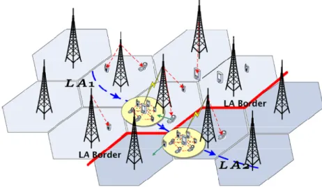
Fig. 5 shows the architecture in GLU where the base stations of the system network are grouped in Location Areas (LAs). As shown in Fig.5 a group of MTs that form a mobile network is moving from LA1 to LA2 which are delimited by LAB (LA Border).
Figure 6: Typical scenario of group location update [15]
In summary, unlike in the classic Individual Location Update (ILU) scheme (where the MTs need to communicate directly with the base stations (vertical communication)), in GLU scheme the MTs communicate with the LMT (horizontal communication); the only one to communicate with the base stations. Obviously, the power cost for horizontal communication is much lower than vertical communication which GLU scheme is exploiting to save power energy of MTs' battery. The location update is then performed by the LMT on behalf of all registered members or GM (Group Members). The information concerning the location of the mobile network [15] is stored in Group Location Database (GLDB). This way, when a call to a MT (or GM) is attempted, the current location of the callee, more exactly the callee group, could be requested from the GLDB. The call can then be established between the caller and the callee of the mobile network. The GLU scheme
realization is based on the implementation of the following operations/procedures: Group establishment, Group leader (re-)selection, join and quit the group, group and location update. More details on these operations can be found in [15]
2.1.3 CoolSpots: reducing the power consumption of wireless mobile
devices with multiple radio interfaces
Pering et al. [17] propose a model called ‘CoolSpots’ that enables a wireless mobile device to automatically switch between multiple radio interfaces. They studied, mainly, the case of switching between short-range to very short-range radio-interfaces, such as between Wi-Fi and Bluetooth. Indeed, only the radio interface that fulfills the need of the MN (of the current running application) will be used and the other interface could be disabled; this will help increasing the battery lifetime of the multi-radio device.
According to Fig. 6, the energy consumption of the main components of a wireless device (in idle state) is dominated by the consumption of Wi-Fi interface; it consumes about 70% of the total energy. In general (according to Table1 page 32), Bluetooth interface is less expensive in term of power consumption than Wi-Fi interface.
Table 1: Comparing power consumption of Wi-Fi and Bluetooth radio interfaces in different states [17].
Interface Low-Power Idle Active Tx
WiFi Cards Cisco PCM-350 390 mW 1600mW NetGear MA 701 264 mW 990 mW Linksys WCF12* 256 mW Bluetooth BlueCore3 5.8 mW 81 mW BlueCore3* 25 mW 120 mW
The authors propose a switching radio interface system (called CoolSpots) that considers power consumption and radio range of each radio interface to determine an optimal radio configuration. In summary, the basic idea behind CoolSpots switching system to determine the radio interface (WI-FI or Bluetooth) to be used (considering their radio states) is to select the one with lowest energy consumption that can satisfy the application requirements (e.g., in terms of bandwidth). As shown in Fig. 7, the interface not in use is switched to PSM (Power Saving Mode) in the case of WI-FI and Sniff4 [28] in the case of Bluetooth; in these modes, the interface energy consumption is reduced.
Figure 8: CoolSpots model consists of radio interface switching.
4 Sniff mode is a low-power mode defined by Bluetooth specifications. The listening rate in this mode is
reduced to conserve battery life.
CoolSpots
Bluetooth Wi-Fi
BT
Experiments [17] show that a substantial energy savings (more than 50% reduction in energy consumption of the MN could be achieved when using CoolSpots.
2.1.4 Wake-on-wireless: An event driven energy saving strategy for
battery operated devices
Generally, PDAs (Personal Digital Assistants) use Wi-Fi to connect wireless LANs; this quickly drains PDA battery after only few hours being in non-active/idle state. Unlike Wi-Fi technology, cellular phones have up to several days for their idle lifetimes. Fig. 8 compares lifetime of a cell phone (GSM Motorola V60t) against a PDA (Compaq iPAQ H3650 equipped with a WiFi interface) both in standby mode. In the case of PDA, two modes are considered CAM (Continuously Awake Mode) and PSM (Power Save Mode) which allows more power saving. Fig. 8 shows that a cell phone has lifetime 3 times bigger than PDA using PSM and 10 times bigger with using CAM.
Figure 9: Comparing standby lifetime of a Motorola V60t (cell phone) with an IEEE 802.11b card in PS/CAM modes [18].
In wake-on-wireless [18], the authors introduce a technique that helps increase the battery lifetime of a PDA ideally make it comparable to the lifetime of a cell phone by reducing the power consumed when it is in ‘idle’ state (as opposed to active state). To reduce this unused power energy, the authors propose to shut down the device and its wireless network card when the device is not in active communication. The device is then powered on only when an incoming call arrives and obviously when sending data.
To wake-up the device wake-on-wireless uses a secondary low-power radio interface (thus consuming far less energy than Wi-Fi and supporting low data rate); the secondary interface uses a frequency band that is different from the frequency band used by Wi-Fi. Thus, when the device is not actively in use, the high-power wireless card (Wi-Fi) is shutdown while low-power interface remains active to receive wake-up messages when an incoming call arrives. Once awake, the device accepts the call on its primary high rate and high power interface (Wi-Fi).
Analysis results show that wake-on-wireless can increase the battery lifetime of PDAs (using PSM) by up to 115%.
2.1.5 Cell2Notify: Wireless wakeups revisited: Energy management for
VoIP over Wi-Fi smartphones
Agarwal et al. [16] propose a solution, called Cell2Notify, to reduce energy consumption of a MN equipped with two radio interfaces, namely Wi-Fi and 3G, used mainly for voice communication. The basic idea of Cell2Notify is to leverage the cellular radio interface (that consumes far less energy, when in idle mode, as shown in Fig. 12) to implement a wake-up mechanism of the Wi-Fi interface (that is powered off when in idle mode).
Fig. 9 [16] shows energy consumption, in different modes, of 2 cellular radio interfaces (VeriZon V620 and SE-GC83) and 1 Wi-Fi radio interface (Netgear WAG511). The power consumption of WiFi interface is smaller (75% less), compared to cellular
interfaces, when in active mode. This is mainly due to the fact that the distance between the cellular device and the serving base station is usually very big (up to miles) which requires high transmit power energy from the device. This is not the case for the Wi-Fi interface which is usually close to the serving access point (a few 100s meters). Thus, ‘Cell2Notify’ (1) uses Wi-Fi interface, whenever possible, for voice communication; and (2) shuts down the Wi-Fi interface when it is not used (idle mode).
A typical setup, when using Cell2Notify, consists of MNs in enterprise environment with access to two networks: (1) WLAN which provides access to Internet; and (2) Cellular network which provides access to PSTN (Public Switched Telephone Network). A MN can be joined through either networks; using the Wi-Fi interface, a MN can use a SIP (Session Initiation Protocol) server in the LAN to establish a communication with MNs connected to PSTN. Cell2Notify architecture is based on classic server/client architecture where the MN (‘Cell2Notify’ client) has to register its Wi-Fi interface at the SIP server (‘Cell2Notify’ server) and then shuts it down. The SIP server maintains a list of registered MNs; it intercepts SIP incoming calls and sends a message through the cellular network (thus via the cellular interface) to wake-up the concerned Wi-Fi interface. Upon wake-up, the Wi-Fi interface re-establishes its wireless connection with the WLAN and gets ready to receive the call.
2.2. Analysis
In this chapter, different techniques, concerning saving battery energy of a handheld device equipped with multiple radio interfaces, were presented. In summary, to save energy in multi-radio devices, existing contributions either focus on a single wireless technology (e.g., Bluetooth or IEEE 802.11b), define switching policies between different radio interfaces (between Wi-Fi and Bluetooth), or extend the SIP server functionality to be able to intercept calls (at application level) coming to its registered client. All these contributions have a limited/restricted scope:
1. Hybrid location-Update Scheme [12] proposes an algorithm that predicts the optimum time and/or conditions (number of boundaries cells crossed) that trigger a location update procedure as a way to save energy. However, it does not address the issue of high energy consumption of a mobile using multiple radio interfaces especially when they are not active (situations where the power/energy consumption is important).
2. The autonomic group location update (GLU) [15] is limited to a mobile network, where one selected MN performs location update on behalf of all the other members. Although, this work does address the issue of consumed energy when the interface is idle and when location update is performed, it does not consider the case of multi-radio devices. In this case, the problem becomes much more important and this solution will be much more complicated to apply. Another limitation of this contribution concerns the location update; it is not clear when the location update should be triggered and when the MN should consider its location has changed.
3. CoolSpots [17] considers a MN with multiple interfaces (Wi-Fi and Bluetooth) of short range. The proposed solution considers switching to the interface that satisfies the currently used application requirements and drains less energy.
Even if this solution helps saving energy, it is still not efficient. Indeed, CoolSpots does not power off interfaces even in idle mode; this causes energy consumption withourt being used for effective communication; furthermore, CoolSpots applies only to WiFi and Bluetooth. .
4. The Wake-on-wireless [18], proposes to use an extra short range wireless interface (low power) to wake up the (powered off) interface used for data communication. Although this solution allows saving energy, it requires the usage of an extra short range wireless interface when the data interface is powered off. To satisfy this requirement, a large number of APs (to cater to the short range interface) is needed; this makes Wake-on-wireless very difficult, if not impossible, to use in general. Furthermore, the usage of Wake-on-wireless, as described in [18], is limited to SIP-based VoIP calls.
5. Cell2Notify [16] powers off the Wi-Fi interface when it is not active to save energy. The second interface (3G interface) is used to wake-up the Wi-Fi interface when an incoming VoIP call arrives. Cell2Notify solution is limited to SIB-based VoIP calls. Indeed, if WiFi is powered off and an incoming call (other than SIP-based VoIP calls) arrives, Cell2Notify will not be able to power on WiFi. Thus, to support different types of calls, Cell2Notify should not power off the WiFi interface; in this case, no energy saving can be provided.
Table 2: Metric-based comparison of representative energy management contributions Approches Considers multi-interface Range of considered interfaces Wake-up mechanism LU
mechanism Complexity Energy Saving
Integrated with a standard
Hybrid LU
Scheme No All No No Simple Low No
Autonomic
GLU No Short No Yes Complex Medium No
Cell2Notify Yes Short Yes but
limited to SIP apps
No Complex High
No
CoolSpots Yes Short No No Simple Low No
Wake-on-wireless Yes Short
Yes but limited limited SIP apps No Complex High No
IMIP Yes All
Yes without
limitation Yes Complex Very High Yes (MIH)
Table 2 shows that unlike some solutions in the literature, IMIP is not limited to a specific type of applications (e.g. VoIP) or upper layer protocols (e.g. SIP). IMIP is designed to provide the power management of wireless interfaces used to establish connections between any upper layer protocols and/or applications. It has no limitations on the types of interfaces that a mobile device can use; it also provides a solution to location update for powered-off interfaces. Furthermore, IMIP extends MIH standard; thus, it has the potential to be adopted in a newer version of MIH (amended MIH). The
experimentations results (see the next 2 chapters) show that IMIP outperforms existing approaches in terms of energy savings. .
Chapter 3
A Framework for Power Management of Handheld
Devices with Multiple Radios
Context
The problem with idle radio interfaces (in idle mode) is that even when not active they still drain the battery. The problem is considerable for mobile devices equipped with multiple radio interfaces as they contribute to reduce the battery lifetime which directly impacts the utility of the mobile device.
It is true that a mobile device equipped with multiple radio interfaces provides the ability to the end-users to achieve ubiquitous and seamless connectivity anytime, anywhere across heterogeneous wireless networks (e.g., Wi-Fi, WiMAX, LTE); however, the existing power management solutions for idle interfaces, defined individually by wireless technologies, are not efficient which ends with considerable amount of battery energy lost.
In this chapter, we present our solution; a framework for integrated power management of handheld devices equipped with multiple radio interfaces. This framework, based on an extension of the MIH standard, allows considerable energy savings. The basic idea of our solution is to proxy idle interfaces using a proxy entity in the network and active interface in the MN. Unlike the existing power management solutions, our solution considers all the radio interfaces as elements of one system (the mobile device) rather than considering them isolated interfaces.
The results of this work are presented in the following paper entitled “A Framework for Power Management of Handheld Devices with Multiple Radios” published in the proceedings of IEEE WCNC2009 [10].
A Framework for Power Management of Handheld Devices
with Multiple Radios
Abstract
The new generation of handheld devices is equipped with multi-radio interfaces that enable radio link connections to a variety of wireless networks (i.e. Wi-Fi, WiMAX).This allows for seamless connectivity; however, this also raises a serious issue concerning the short longevity of the handheld usability due to the high power consumption of the wireless interfaces. In this paper, we present a framework that increases considerably the battery longevity of the handheld devices; it enables efficient power management from a global point of view (and not a single radio interface view) of multi-radio devices. The basic idea behind our proposal is to power off the idle interface but at the same time to keep it in virtual idle mode in the network by extending IEEE 802.21 on both sides (the mobile node side and the network side). On the network side, the 802.21 entity acts as a proxy of the powered-off interface to ensure the assigned resources for the interface are always maintained during the proxying period. In the context of the proposed framework, we present (details of) the mechanisms to proxy an idle interface (after powering it off) and to wake up a proxied interface respectively. The proposed solution is analytically evaluated to quantify the power savings compared with single-radio power management.
Keywords: Multi-Radio Power Management, Idle/Active mode, Proxy,Proxied interface, MIH services.
H. Mahkoum, A. Hafid Network Research Lab.
University of Montreal Montreal, Canada H3T 1J4
Behcet Sarikaya Huawei Technologies, USA
1700 Alma Dr. Plano, TX USA 75075
I. Introduction
Multi-radio devices provide end-users the ability to achieve ubiquitous and seamless connectivity anytime, anywhere across heterogeneous wireless networks (e.g., Wi-Fi, WiMAX); however, these radios consume large amounts of energy. The utility of the devices is directly impacted by the longevity of their operation before batteries need to be replaced or recharged. Thus, the challenge is to design multi-radio devices that use energy efficiently; the objective is to provide the benefits of using multiple radios with low energy consumption.
According to [3] and [4] the radio interfaces in a PDA are the main source of energy consumption. Equipping a device with multiple radio interfaces decreases the time of its operation/usage as its battery gets empty quickly. Energy consumption of each radio interface depends on its radio state. When transmitting data, the consumed energy is the highest; it is less when receiving and almost the lowest when in idle state. Usually, a multi-radio interface device is continuously consuming power because all its multi-radio interfaces, when they are not transmitting or receiving, are in idle state where they continue using the battery power. Researchers, focusing on different wireless technologies, have addressed the energy consumption issue from their own scope and they ended with definitions of idle mode and/or sleep mode as a way to save the energy.
In [1], the authors propose a scheme to reduce energy consumption of a PDA-based phone by reducing its idle power consumption. The device and its wireless network interface (IEEE 802.11b) are shut down when it is not used; the device is powered only when an incoming call is received. This scheme uses a second low-power wireless radio connection; out-of-band control information is sent to maintain connectivity and wakeup the device when necessary. These types of radio typically have very small radio coverage; thus, to support the scheme in [1], a high density wireless infrastructure deployment is needed.
The authors in [2] propose a system that enables a multi-radio mobile device to automatically switch between multiple radio interfaces in order to increase battery lifetime.
More specifically, based on empirical measurements, the proposed system makes 2 decisions: when to “switch-up” to Wi-Fi to increase available bandwidth, and when to “switchdown” to Bluetooth and power-off Wi-Fi to conserve energy.
In order to save energy, the authors in [3] propose a solution that allows powering-off a Wi-Fi interface and waking it up, through a 3G connection (consumes less energy than a Wi-Fi connection), once a VoIP call arrives on the proxy SIP server where the Wi-Fi interface is registered. Although, the proposed solution helps saving energy, its applicability is limited; it is essentially based on the interception of a VoIP call at the application level (SIP server).
In summary, most existing schemes to save energy in multi-radio devices either focus on a single wireless technology (e.g., Bluetooth or IEEE 802.11b), define switching policies between different radio interfaces (between Wi-Fi and Bluetooth), have limited/restricted scope (e.g., intercept a call at application level using a SIP server).
In this paper, we make use of the MIH (Media Independent Handover) standard; and our contribution consists of reusing the predefined MIH messages and defining new ones service access points and the network entities (PoS). The idea is to extend the MIH services to include a new service (called MRPM: Multi-Radio Power Management) that supports integrated power management of multi-radio handheld devices. Because of lack of space, we present, in detail, only two mechanisms to illustrate the processes to (1) proxy an idle interface after powering it off; and (2) to wake up a powered off interface after a call arrival (i.e., connection request, such as VoIP call or data request). Location update, mobility and handover on active interface mechanisms will be described in future papers.
The primary contribution of this paper consists of the extension of MIH standard (called EMIH: Energy-aware MIH) to support efficient power management, from a global point of view (and not a single radio interface view), of multi-radio devices. More specifically, we define a new set of primitives and a new MIH service that supports integrated power management of multi-radio devices; we also present, in detail, the interactions including the exchanged primitives between the framework entities to (1) proxy an idle interface (after shutting it down); and (2) wake up an powered off interface
(upon a call arrival). Our proposed solution can be used with any wireless networking technology; it can be easily augmented with “optimal” policies to switch between radio interfaces, and can be used with any MIH capable system.
The rest of this paper is organized as follows. Section II presents a description of the proposed framework. In Section III, we present the details of the interactions to proxy an idle interface after powering it off and to wake up a powered off interface (upon a call arrival). Section IV evaluates the performance of our proposal. Section V concludes the paper.
II. Energy Saving Framework
We propose a framework for an effective management of power of a multi-radio MN. The framework considers the power management of mobile devices from a global view contrary to the single radio power management proposed by each wireless standard. The best way to save energy is to power-off an interface when it is idle. Then, the problem becomes how to stay connected to the network of the powered-off interface; this connection is needed to process the calls, to the device, that arrive on that interface. In this case, the interface could be powered-on to exit the idle state and get ready to receive the calls.
In this paper, we propose a scheme to solve this issue; the basic idea behind the scheme is to keep a proxy network entity for each powered-off interface. The proxy acts on behalf of the powered-off interface. The proxied interface is considered, by the network, as an interface in idle state. Thus, the network maintains the resources allocated to the interface; if a call arrives, the proxy will be notified by the network and then it will send a wake-up message to the device, through the currently active interface, to wake up the powered off interface (we assume that there is at least one radio interface that is connected and not idle). After waking-up, the interface will handle the incoming call. In this paper the remainder of this Section is organized as follows. Section II.A briefly presents the elements of the MIH standard we will use in the proposed framework. Section II.B describes the idle
mode as defined by WiMAX [6] and LTE (Long Term Evolution) [7]. In this paper, we consider the power management of the radio interfaces independently of any specific wireless technology as long as idle mode is defined. Wi-Fi technology is not considered, because it doesn’t define idle mode (only sleep mode is defined). We consider proxying Wi-Fi interface a special case to be addressed in the future. Section II.C presents the details of the multi-radio node architecture. Section II.D describes the communication model among the entities of the proposed architecture.
A. MIH Services
IEEE 802.21 standard or Media Independent Handover (MIH) [5] defines a framework that enables service continuity while MN transitions between heterogeneous link-layer technologies also known as inter-technology handover. MIH is composed of three layers (see Fig. 1): (1) MIH user; (2) MIHF (Media Independent Handover Function); and (3) Radio media interface.
The MIH user receives the state changes of interfaces as events and consequently sends control signals to the lower layers as commands. MIH Function (MIHF) is the protocol standard which provides three services: ‘Command’ service (CS), ‘Event’ service (ES) and ‘Information’ service (IS). MN uses the specific media to establish the radio link with its corresponding network (CN).
These layers communicate through service access points. MIH user and MIHF layers use MIH_SAP to communicate and MIHF and network interfaces use MIH_Link_SAP (or LinkLayerControl_SAP) to communicate the services primitives. Finally, the network and MN use the MIH_NET_SAP as a service access point to communicate remotely (see Fig. 1).
B. Idle Mode in WiMAX and LTE Networks
When IEEE 802.16e interface is not active, to save power, WiMAX standard [6] has defined the idle mode. In idle mode, the interface is managed by the Paging Controller (PC) and is not specifically connected to a particular base station (BS). The energy savings come mainly from the fact that the interface is not required to be all the time available. But, to be able to respond to the network requests it should periodically become available to check whether there is any call/data coming to it. When a call arrives on the network for the MN, the PC sends a paging message to the BSs that belong to the paging area where the MN is located (has been seen for the last time). The BSs, of that paging area, broadcast the paging message and the MN should now be available to receive the paging message and react accordingly.
In LTE system [7], the UE (User Equipment5) is managed and controlled, at the
level of the control plane, by the MME (Mobility Management Entity) through NAS (Non-Access Stratum) protocol which runs in both sides. MME is a key control-node for the LTE access-network, among its functions for an active UE: network attachment, authentication, setting up of bearers, and mobility management. It is also responsible for tracking and paging procedure for an UE that is in idle mode. In idle state, the UE does not inform the network of each cell change; its location is only known, at the MME, at the granularity of a TA (Tracking Area) which consists of multiple eNBs (evolved Node Bs). So, when a call
arrives for an UE (in idle state), for example, the MME sends a paging message to the TA where the UE lastly registered or is located.
C. Multi-radio mobile node architecture
Fig. 2 illustrates how the proposed framework ensures the communication and coordination between the MN and the proxies, on different networks, concerning the proxied/powered-off interfaces. The figure shows a heterogeneous network composed of 3 different networks (WiMAX, Wi-Fi and LTE) and a mobile node with 3 interfaces, two of them are in power-off state and the third one is in active state. The powered-off interfaces are proxied on their network by the corresponding Proxy entity/Point-of-Service (PPoS), the third one, in active state, is used to maintain the signaling session between PoS and Network Selection Entity (NSE).
Serving PoS is an MIH network entity that exchanges MIH messages with the MN, concerning the current/active interface, to prepare for an eventual handover to another one. The message exchange takes place between the MIHF layers of the MN and the serving PoS when preparing for a handover. To benefit from the PoS services, the MN has to
Parameters Proxied Interface MN IP Address 107.18.90.61 Mac Address 00-08-74-4C-7F-1D IP Address 67.68.93.162 Location (Area / PoA) Paging Area XYZ / ref # abc Duration of absence 30:25 minutes Power Consumption
(Tx, Rx) Tx 0.9 mW / Rx 0.2 mW
Parameters Proxied Interface MN IP Address 107.18.90.61 IMSI 429011234567890 IP Address 70.96.100.22 Location (Area/PoA) Tracking Area XY1 / ref # ab Duration of Absence 10:05 minutes Power Consumption
(Tx,Rx) Tx 1.9 mW / Rx 0.3 mW
![Figure 1: Circuit card with 3 fully integrated radio technologies [21]](https://thumb-eu.123doks.com/thumbv2/123doknet/11344482.284319/16.918.429.569.601.711/figure-circuit-card-fully-integrated-radio-technologies.webp)


![Figure 5: Frequency of location updates between two calls in hybrid scheme [12]](https://thumb-eu.123doks.com/thumbv2/123doknet/11344482.284319/34.918.178.818.264.572/figure-frequency-location-updates-calls-hybrid-scheme.webp)
![Figure 7: In idle state the Wi-Fi interface consumes approximately 70% of the total power [17]](https://thumb-eu.123doks.com/thumbv2/123doknet/11344482.284319/37.918.353.654.695.989/figure-idle-state-interface-consumes-approximately-total-power.webp)
![Table 1: Comparing power consumption of Wi-Fi and Bluetooth radio interfaces in different states [17]](https://thumb-eu.123doks.com/thumbv2/123doknet/11344482.284319/38.918.236.774.209.392/table-comparing-power-consumption-bluetooth-interfaces-different-states.webp)
