HAL Id: hal-02498627
https://hal-mines-albi.archives-ouvertes.fr/hal-02498627
Submitted on 6 Mar 2020
HAL is a multi-disciplinary open access
archive for the deposit and dissemination of
sci-entific research documents, whether they are
pub-lished or not. The documents may come from
teaching and research institutions in France or
abroad, or from public or private research centers.
L’archive ouverte pluridisciplinaire HAL, est
destinée au dépôt et à la diffusion de documents
scientifiques de niveau recherche, publiés ou non,
émanant des établissements d’enseignement et de
recherche français ou étrangers, des laboratoires
publics ou privés.
Experimental evaluation of vitrified waste as solid fillers
used in thermocline thermal energy storage with
parametric analysis
Muhammad Asaad Keilany, Mathieu Milhé, Jean-Jacques Bézian, Q. Falcoz,
G. Flamant
To cite this version:
Muhammad Asaad Keilany, Mathieu Milhé, Jean-Jacques Bézian, Q. Falcoz, G. Flamant.
Experimen-tal evaluation of vitrified waste as solid fillers used in thermocline thermal energy storage with
para-metric analysis. Journal of Energy Storage, Elsevier, 2020, 29, pp.101285. �10.1016/j.est.2020.101285�.
�hal-02498627�
Experimental evaluation of vitrified waste as solid fillers used in thermocline
thermal energy storage with parametric analysis
M.A. Keilany
a,b,⁎, M. Milhé
a, J-J. Bézian
a, Q. Falcoz
b, G. Flamant
baCentre RAPSODEE, Universite de Toulouse, Ecole des Mines d'Albi, CNRS, Albi F-81013, France bCNRS-PROMES, 7 Rue du Four Solaire, 66120 Font Romeu-Odeillo, France
Keywords:
Thermal energy storage Pilot-scale thermocline for CSP Performance parameters Discharge/charge efficiencies Thermolicne thickness
This work presents the first use of Cofalit® (vitrified asbestos-containing waste) as a solid filler in pilot-scale thermocline thermal energy storage (TES). The thermocline size is 4 m³ connected to the MicroSol-R installation at the PROMES research facility in Odeillo, France. The study compares the thermal performance of the ther-mocline filled with Cofalit® to the reference case of alumina spheres for typical charge and discharge operations. It evaluates the actual thermal behavior of thermocline considering three leading performance indicators: process duration, thermocline thickness, and process efficiency. The investigation shows a 22% shorter charge duration in Cofalit® compared to alumina and 16% shorter discharge duration. Cofalit® exhibits about 16% lower thermocline thickness during both charge and discharge compared to alumina. The charge efficiency is slightly better in Cofalit® than alumina with an efficiency of 82% and 78%, respectively. Also, Cofalit® has a better discharge efficiency, 90% with respect to 84% for alumina. These results confim a good thermal per-formance of Cofalit® as filler material in thermocline TES. Considering the cost-saving and positive environ-mental impact of using Cofalit® as well as the good thermal performance of the thermocline filled with it, Cofalit® appears a very good filler material in TES. The obtained temperatures from radial positions indicate no significant variation during charge and discharge, and this confirms the one-dimensional thermal behavior of this setup. A parametric analysis is performed using a 1D continuous solid (C-S) model to investigate the in-fluence of particle diameter, porosity, thermal conductivity, and volumetric heat capacity on the thermal per-formance of the thermocline. The analysis confirms the experimental findings, and it indicates that about a 10.9% longer process duration is associated with a 10% larger volumetric heat capacity and less affected with other parameters. Thermocline thickness is mainly affected by the diameter as well as the volumetric heat capacity of the solid filler; it grows 2.2% for each 10% diameter increase and around 3.23% for doubling the volumetric heat capacity. Charge efficiency demonstrates independency from evaluated properties. While dis-charge efficiency increases sharply at a tiny particle diameter before an optimum diameter value is reached, then it starts to decrease by 1.4% to each 10% bigger diameter.
1. Introduction
Thermal energy storage (TES) is playing a significant role in re-newable energy resources development, as well as energy conservation applications. From one side, it allows intermittent solar energy supply to fill the gap with the demand side and increase competitiveness against fossil fuel resources[1]. And from the other hand, it has a vital contribution in developing efficient thermal applications similar to air conditioning heat sinks, space, water heating, and cooling [2]. There are three main categories of TES: sensible heat, latent heat, and thermo-chemical heat storage. Moreover, there new approach to combine both sensible and latent heat storage media in the same tank to improve the
performance of TES[3–5]. Sensible heat thermal storage is currently commercially dominant[6] because it satisfies most of the required criteria for TES, such as materials availability at low cost, thermal and chemical stability at various working temperatures, relatively high volumetric heat capacity and low thermal expansion[7].
Thermocline TES systems could be an economically viable solution for TES in concentrated solar power plants (CSP) and thermal energy recovery systems. It can replace the two-tank TES system by a single tank filled with cheap solid filler materials to increase the volumetric heat capacity of the TES and decrease the need for expensive heat transfer fluid (HTF). Pacheco et al.[8]concluded that such a solution could reduce the cost of the two tanks molten salts TES by 34%.
⁎Correspondign author at: Centre RAPSODEE, Universite de Toulouse, Ecole des Mines d'Albi, CNRS, Albi F-81013, France.
E-mail address:mkeilany@mines-albi.fr(M.A. Keilany).
However, during a charge/discharge process, a thermal gradient layer typically develops between the hot and cold regions of the tank, which is called the thermocline region. The quality of stored/released energy is degraded inside this region, while this layer is expanding during the operation. It could account for up to 33% of total tank height[9], which reduces the efficiency of the system by shortening the useful time of operation and available heat. Mira-Hernández et al. [10]concluded that using solid filler material in thermocline TES implies a larger thermocline thickness when compared to solely liquid storage, and the author ascribed that to the higher thermal diffusivity of the solid filler materials compared to the HTF. However, heat exchange limitation between HTF and solid filler when introducing the latter could be the first reason for a bigger thermocline thickness, then the thermal diffu-sion of solid filler. The most influencing parameters on thermocline thickness are tank height, and more generally, the aspect ratio of tank height over diameter and thermos-physical properties of the solid filler
[11], higher tank and more thermal diffusive materials lead to a larger thermocline thickness. Other parameters have less impact on cline thickness, such as the diameter of the solid filler, porosity, thermo-physical properties of the HTF, and charge time, while Bonanos and Votyakov[11]did not evaluate the mass flow rate. J.F.Hoffmann at el
[12] demonstrated that there is an optimal mass flow rate for each particle size that leads to maximum efficiency. Below a specific value of mass flow rate, the thermal losses in the system will dominate and negatively affect the thermal behavior of the thermocline; while at high mass follow rate, strong force convection could induce a higher heat flux within the HTF compared to the one exchanged between HTF and solid filler.
When selecting a suitable solid filler material for TES, numerous thermo-physical, chemical, mechanical, environmental, and economic characteristics must be considered [13]. Different materials in-vestigated for potential use as sensible heat storage for CSP. For ex-ample, many reserachs evaluated HIETC solar salt, mineral oils, syn-thetic oils, silicone oil, nitrite salts, carbonate salts, and liquid sodium
as liquid storage media, and as solid strogae media materials such as sand, rock, concrete (various grade), NaCl (solid), cast iron, cast steel
[14–16] are observed. However, commercial solar power plants are using only molten salts, mineral oils, sand[17].
In this context, the use of recycled materials as solid filler in com-mercial TES is of high interest, because it helps to reduce the cost as well as the environmental impact of TES. For example, France produced about 250,000 ton of asbestos-containing wastes (ACW) a year in the last two decades, out these only 6000 tons re-used in roads construction
[18], while the rest stays in a highly controlled waste landfill, under rigors rules of stockpiling, expected to be treated. France's case could be projected to other industrial countries, unveiling the high potential of ACW recycled materials.
There are five main catagories of recycled materials[19]: municipal wastes, fly ashes, slags from the metal producing process, by-products from salts industries, and ACW. Various studies examined the potential use of these materials as solid filler in TES: municipal waste was eval-uated in [[19],[20]], fly-ash was tested in[21–23], and a wide ranges of waste products from metal production process were considered in
[11–14], secondary products from salt industry were assessed as sen-sible or latent heat TES in[25–27], while ACW was studied extensively in [[18],[21],[28–35]]. However, most of these studies were conducted only to characterize the materials as well as evaluating thermo-physical properties, stability, or compatibility with different HTF, but none evaluated the performance of filler materials in pilot or plant scale TES. Motte et al.[36]numerically evaluated a structured thermocline TES using vitrified ACW filler. The TES was specially designed in a wall shape structure, while the solid filler is ACW in building brick shape, and the HTF is solar salt. The convective heat transfer coefficient was found lower in this configuration when compared to a more common packed-bed thermocline, and this makes such a setting is undersirable. Ortega-Fernández et al.[37]experimented with a 3 m³ thermocline TES a steel slag as filler materials. The storgae recovered heat from high-temperature exhaust gases of an electric arc steelmaking furnace
Nomenclature
ATank int Internal Tank cross-sectional area [m2]
Awall cross section Tank’ wall cross-sectional area [m2]
Af↔w Exchange heat transfer area between fluid and tank's wall
[m2]
Aw↔ext Exchange heat transfer area between tank's wall and
sur-rounding environment [m2]
as Shape factor [1/m]
Cp Heat capacity [Joul/kg.K]
dr The average diameter of a particle [meter]
dch Hydraulic diameter (characterize diameter) of rocks
[meter] E Energy [Joul]
Htank Thermocline's Height [m]
HThick Thermocline thickness size [m]
hv Volumetric convection heat transfer coefficient between
HTF and Solid filler particles [watt/m3.K]
hf p Convection heat transfer coefficient between HTF and
Solid filler particles [watt/m2.K]
hw convection heat transfer coefficient HTF - tank's wall
[watt/m2.K]
hext convection heat transfer coefficient between the tank's
wall and the surrounding atmosphere [watt/m2.K]
k Thermal conductivity [watt/m.K] kc Charge factor [ ]
kd Discharge factor [ ]
k Heat conductivity [watt/m.K]
Lch Characterized length [m]
T Temperature [K]
Tz, t The temperature at axial position z at time t [K]
Tlow The lowest temperature inside the system initial
tem-perature during charge/ Inlet temtem-perature during dis-charge [K]
Thigh The highest temperature inside the system inlet
tempera-ture during charge/ initial temperatempera-ture during discharge [K]
t Time [second] V Volume [m3]
vf The local velocity of HTF [m/sec]
z Axial coordinate [m]
Greek symbols
ɛ Tank porosity (void fraction) [ ]
α Thermal diffusivity [m2/second]
ρ density [kg/m3]
θ Non-dimensional temperature [ ]
δ Non-dimensional thermocline thickness [ ]
η Efficiency Subscripts
f Heat transfer fluid p Solid filler particles w Tank's wall (wall) * Non dimensional
during charge, and during discharge, the thermocline provided a con-tinuous heat source for the batch operation of the stove with 85% ef-ficiency. No further analysis of either other performance parameters or comparison to other materials was applied.
Other experimental and numerical analysis of thermocline TES used referenced filler materials such as alumina spheres [38–41], and a various type of rocks such as quartzite, [[8],[42–44]] and pebbles
[45–48].
This study is the first experimental testing of vitrified recycled ACW as a solid filler inside a pilot-scale thermocline TES integrated with a small CSP plant. Furthermore, the thermal performance of the ther-mocline TES filled with two different materials, Cofalit® and alumina spheres (the reference case), is assessed. This work takes a new ap-proach to evaluate the thermal behavior of thermcoilne TES based on three main performance parameters: process duration, thermocline thickness and process efficiency. Finally, it conducts a parametric study using a previously validated one-dimensional continuous solid model
[49], to evaluate the most influencing property on the thermal per-formance of thermocline TES.
2. Materials and methods
2.1. TES storage filler materials
Cofalit® is an inert and low-cost post-industrial process rock (re-cycled material from asbestos wastes), supplied by the French company Inertam [30]. The company produces around 3000 tons yearly by subjecting ACW to plasma torch furnace at 1400 °C, then leaving the molten resultant to cool down to ambient temperature without specific operation to control the process[34]. The liquid nature of the primary products allows forming molten Cofalit® in the required shape as molded. It was identified as a chemically inactive material[31]and is thermally stable up to 1200 °C[30]. It was found compatible with two common HTF: the binary salt composed of 60% wt. sodium 40% wt. potassium nitrates, and the ternary salt composed of 42% wt. calcium, 15% wt. sodium, 40% wt. potassium nitrates [32]. Furthermore, its stability was confirmed when evaluated with synthetic oil used in this experimental setup at 300 °C[33].
Various studies reported a low environmental impact of Cofalit®, as
it has no toxicity on the environment and is not subject to lixiviation [[18],[28],[30]]. Although Jeanjean et al. [50]estimated a carbon footprint of 27.48 gCO2/kg for Cofalit® production, the environmental
impact is due to asbestos thermal treatment (melting) and not to its re-use in a TES tank[34].
In addition to safety consideration, the re-use of Cofalit® provides an economic advantage when compared to an organic HTF, because it costs about 12 $/ton[30], while the latter costs about 1962 $/ton[51]. Based on these properties, Cofalit® is an interesting solid filler for sensible heat TES, with significant advantages, such as low cost, rela-tively high volumetric heat capacity, and revalorization of waste ma-terials. This study selects alumina spheres as reference material with controlled geometry and well-known thermo-physical properties. Alumina was studied as solid filler materials in thermocline TES in various studies[38–41].
2.2. Experimental setup
The experimental setup used in this work to carry out the compar-ison between Cofalit® and alumina is the one used by Fasquelle et al.
[52]. MicroSol-R is a pilot-scale CSP plant consisting of three parabolic troughs (12 m long, 5.76 m aperture, and focal length 1.7 m, equipped with 7 cm in diameter receiver) with total nominal power 150 kW(th). The TES is a 4 m³ thermocline tank 3.17 m height and 1.276 m internal diameter. The filler arrangement consists of four vertical bas-kets, reducing the possibility of thermal ratcheting and allowing easy access to change the filler materials. The installation is using thermo-couples to record HTF temperature every 2 s with a precision of ± 0.6 C°, and they are distributed in the axial and radial positions, as illustrated inFig. 1.
The solid bed height is 2.64 m, and two buffer zones enable a homogeneous HTF distribution. During charge, the charge pump flows hot HTF through the top of the tank and extracs cold HTF out of its lower port. For the discharge, the discharge pump injects cold HTF in the thermocline from the bottom and circulates hot oil out of its top. This process design limits the thermal stratification due to the density difference between hot and cold HTF. An electrical heater 70 Kw heats the HTF, in addition to the parabolic troughs when needed during charge, and three stages heat exchangers cool it down during discharge.
Total masses accepted by the same thermocline volume were 4000 kg of Cofalit® rocks and 6380 kg of Alumina spheres, resulting in tank por-osities (void fraction) of 0.614 and 0.485, respectively. Although the Cofalit® rocks in this work have irregular shapes, the final cooling process of ACW treatment could control the size and shape of resultant material, and hence it can easily produce the final product with any required size and shape to fits into the intended application. The solid fillers available for this experiment are a rock with an average diameter of 2 cm and 2 cm alumina spheres (as reference material)Fig. 2.
Table 2summarizes the most cited values of temperature-dependent thermo-physical properties for synthetic oil, alumina spheres, and Co-falit® valid in a temperature range of 200–300 °C.
Discharge tests apply constant operating conditions, with similar HTF mass flow rate as well as temperature difference for both solid fillers. During the charge tests, the same approach was chosen but with a lower mass flow rate and smaller temperature difference compared to the discharge one to achieve constant inlet temperature using the electrical heater.Table 3illustrates the experimental operating condi-tions.
Thighis considered as the highest temperature during a process, and
Tlowis the lowest temperature during the same process, while Toutletis
the HTF temperature at the tank's outlet. Non-dimensional HTF tem-perature and non-dimensional axial coordinate are defined in Eq. (1)
and(2)respectively: = T T T T z t low high low , (1) = z z H * tank (2)
At the beginning of charge operation, both medias are at Tlow, while
HTF at Thighflows downward the tank: then the temperature inside the
tank starts to increase from top to bottom. Reversely during discharge, the filler materials start at Thigh, and cold HTF at Tlowpumps in upward
the tank: then the temperature inside the tank descends from top to bottom.
In this experimental setup, there is no limitation on the HTF tem-perature flowing out of the tank. However, in a real case scenario, a threshold temperature should be taken into account for charge and discharge processes. It is defined for the charging process as the highest temperature that can be sent back to the solar field during the
operation, referred to as Tthr c k, , c in Eq. (3) [40]. This threshold
tem-perature limits the charge state of the TES in real operation.
= +
Tthr c k, ,c Tlow k Tc(high Tlow) (3)
kcis an arbitrary charge factor related to operational aspects of solar
filed, previous studies considered it 20% [[24],[25]]; the non-dimen-sional charge threshold temperature is thr c, , 20%= 0.2. The process of
charging the tank should end when the outlet temperature reaches the charge threshold valueToutlet=Tthr c k, ,c( outlet= thr c, , 20%=0.2).
Similarly, the threshold temperature of the discharge process is the lowest temperature that the downstream thermal process can utilize
Tthr d k, , d.Eq. (4)calculates the discharge threshold temperature:
=
Tthr d k, ,d Thigh k Td( high Tlow) (4)
kdis an arbitrary discharge factor related to the operation of the
downstream process, generally a steam generator. As in previous stu-dies [[24],[25]], the non-dimensional discharge threshold temperature is at thr d, , 20%= 0.8. Discharge operation ends once the HTF
tempera-ture at the outlet of the TES reaches the discharge threshold value.
2.3. Uncertainty of measurements
The experimental setup uses PYRO-SYSTEM® thermocouples type PT100 1/3 B, which has ± 0.6 °C uncertainty, by neglecting the un-certainty of data acquisition switch, this results in 1.71% unun-certainty in temperate reading. Moreover, each thermocouple has position un-certainty of ± 1%, and the mass flow-metering device (Foxboro® Model 84F) has ± 0.5% uncertainty, which will accumulate 4.08% of ex-panded combined uncertainty.
2.4. Thermocline performance indicators
This approach selects three main parameters to evaluate the op-erational behavior of the thermocline TES: process duration, thermo-cline thickness ratio and process efficiency.
2.4.1. Process duration
Charge (resp. discharge) duration is the time required for the tank outlet temperature to reach its charge (resp. discharge) threshold temperature, θthr, c, 20%(resp. θthr, d, 20%).
Process duration is not only important to extend the time of useful utilization of stored energy, but it also helps to increase the efficiency of the discharge process as introduced in section (3.1.3 Charge and dis-charge efficiencies).
2.4.2. Thermocline thickness ratio
The size of the thermocline (thermocline thickness) is the height of the zone inside the tank that is bounded by the two threshold tem-peratures during charge and discharge (Eq.(5)). It is the part of the storage that the power plant cannot utilize during real operation.
=
HThick H T(thr d, ,20%) H T(thr c, ,20%) (5) The thermocline thickness ratio is the ratio between the thermocline thickness to the total tank height, as perEq. (6).
= H H
Thick
Tank (6)
Fig. 2. Filler materials shape.
Table 1
presetns the axial positions of the thermocouple: Thermocouples axial positions.
Thermocouple TC1 TC2 TC3 TC4 TC5 TC6 TC7 TC8 TC9 TC10 TC11
Axial position (m) 0.05 0.13 0.23 0.36 0.57 0.61 0.78 0.85 0.96 1.09 1.19
Thermocouple TC12 TC13 TC14 TC15 TC16 TC17 TC18 TC19 TC20 TC21
This ratio is required to be as small as possible because large ther-mocline thicknesses characterize low TES efficiency TES [11]. The thermocline thickness ratio is the thermocline thickness in the fol-lowing.
2.4.3. Process efficiency
Due to the significant contribution of the steel in the stored energy in this pilot thermocline, all calculations take into account the volu-metric heat capacity of the wall and the baskets. Furthermore, effi-ciency calculations assume that all internal components of the tank (HTF, solid filler, and wall) are at the same temperature.
The efficiency of the charging process is the ratio between the ac-cumulated energy and the potential stored energy in the tankEq. (7) [51]: = = + + t E t E A Cp A Cp T T dz V Cp V Cp T T ( ) ( ) ( . ( . ) . ( . ) ). ( ). [ . ( . ) . ( . ) ]. ( )
charge accmax H
Tank int eff wall cross section w z t low tank eff w w high low
0 ( , )
(7) Where:( .Cp)eff = ( .Cp)f +(1 )( .Cp)p.
During the discharge process,Eq. (8)calculates the discharge effi-ciency as the ratio of discharged energy to the initial maximum energy stored in the system.
= = + E t E m Cp T T dt V Cp V Cp T T (t) ( ) . . ( ). [ . ( . ) . ( . ) ]. ( ) discharge discharge initial t Kd f f outlet low tank eff w w high low
0 ( )
(8)
2.5. Numerical modeling
There are various physical approaches to model the thermal beha-vior of thermocline TES, such as the Schumann model, the perturbation model, continuous solid models, and concentric dispersion models[56]. Various researchers validated the 1D model approach to providing re-liable temperature prediction of thermocline TES [[39],[49]]. Also, the results from 2D and 3D models did not exhibit any significant tem-peratures variation on the radial axis [[9],[10],[57]]. Moreover, the results of a 1D model generated similar accuracy of a 3D CFD model upon comparsion for the same TES[58].
This experiment setup (Appendix A.1 Experimental radial tem-perature distribution) confirms that there are no significant tempera-ture fluctuations on the radial axis. Hence, it provides a validation of the one-dimensional thermal behavior of the thermocline.
The model used in this study is one-dimensional based on the va-lidated model of Hoffmann et al.[49]. It depicts the thermocline as a cylindrical tank, where heat transfer is occurring only in the axial di-rection. The thermal response on the thermocline depends on heat
Table 2
Thermo-physical properties from literature at temperature range 200–300 °C.
Type Pilot-scale ®oil Alumina spheres Cofalit ®rocks
Tank porosity ε [-] N/A 0.485 0.614
Particle diameter d [m] N/A 0.02 0.02 average
Density ρ [kg/m³] 910–836[7] 3670 [[33],[38]] 3120 [[30],[19],[53]]
Heat Capacity Cp [J/kg.K] 2158–2476[7] 1038–996[33] 900–964[54]
Thermal conductivity K [W/m.K] 0.113–0.105[7] 20–16[55] 1.55–1.49[54]
Volumetric Capacity ρ.Cp [MJ/m³.K] 1.96–2.07 3.8–3.66 2.8–3.0
Thermal diffusivity α [m²/sec].106 0.06–0.05 5.26–4.37 0.55–0.5
Table 3
Experimental conditions.
Process Charge Discharge
Mass flow rate [kg/h] 2600 2950
Temperature range [°C] 248–280 290–220
Table 4
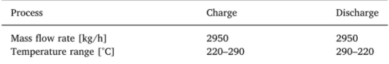
Illustrates the operating conditions for the numerical: Numerical testing conditions.
Process Charge Discharge
Mass flow rate [kg/h] 2950 2950
Temperature range [°C] 220–290 290–220
transfer due to: filler-fluid convection, fluid-wall convection, fluid dis-persion within HTF, conduction between filler, wall-insulation con-duction and convection with ambient air (thermal losses through the tank's wall. The thermal gradient inside the solid filler is neglected (Bi<0.1). Additionally, this work validates the model for both Cofalit® and alumina at the pilot-scale thermoclineAppendix A.2Model Vali-dation). The Model solves three coupled energy balance equations in the HTF, solid filler, and wall temperature profiles (Eqs. (9)–((11), re-spectively).
For the fluid:
+ = + + Cp T t Cp v T z k T z h T T h A V T T . ( ) .f f . ( ) . .f f f f eff. f v. (p f) w. f w. ( ) tank w f . 2 2 (9) For the solid particle:
= + Cp T t k T z h T T (1 ). ( ) .p p p eff. . p v. ( f p) 2 2 (10)
For the wall:
= + + Cp T t k T z h A V T T h A V T T ( ) .w w w. w w. f w. ( ) . . ( ) w f w ext w ext w ext w 2 2 (11)
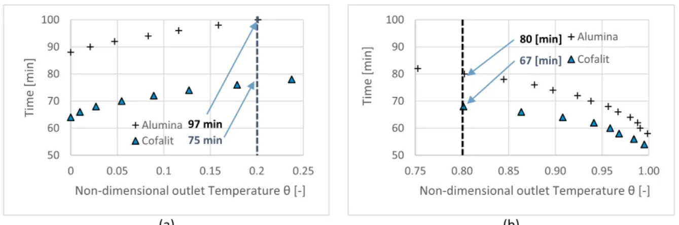
Fig. 4. Alumina and Cofalit® process duration versus non-dimensional outlet temperature (a) charge, (b) discharge.
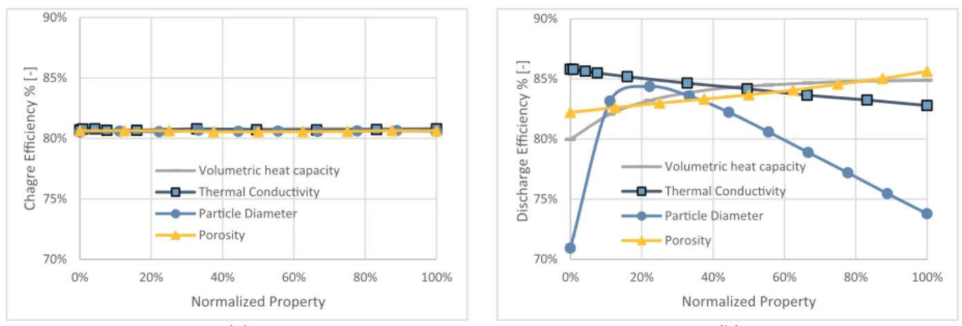
Fig. 5. Alumina – Cofalit® process efficiency versus non-dimensional outlet temperature: (a) charge, (b) Discharge.
WhereEqs. (12)&(13)presents effective thermal conductivities for fluid and solid particle::
=
kf eff. .kf (12)
=
kp eff. (1 ).kp (13)
Eq. (14)calculates the volumetric heat convection coefficient:
= h
h a
v
f p s (14)
asThe shape factor (1/m) identified by the total surface area of all
particles divided by the total volume of the tank[59], as perEq. (15):
= = = = = a A tot V V V V L ( ) (1 ) s p tank V L tank V V L tank V V V L tank ch . (1 / ) p ch tank f ch tank f tank ch (15) And Eq. (16) evaluates the characteristic length for a spherical particle, Lch: = L Volume Area d 6 chdef p (16)
For the Cofalit® simulation, the rocks depicted as regular spheres with a diameter equal to the hydraulic diameter, as it is defined by Li et al.[60]inEq. (17): = d .d 4. (1 ) ch r (17)
dris the average diameter of the rocks.
A Matlab® program was developed to solve the above equations. The model is implicit in time and uses the Crank-Nicholson dis-cretization scheme. The program obtained the numerical solution of the three coupled equations by applying the Newton method with con-vergence criteria of 10 4for each time step. Thermo-physical properties
of HTF and solid filler were considered temperature-dependentTable 2.
3. Results and discussion
3.1. Experimental comparison between alumina and cofalit®
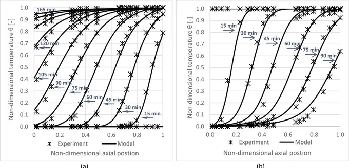
Fig. 3shows non-dimensional temperature profiles inside the TES, against non-dimensional axial positions over the time during (a) charge and (b) discharge test for alumina and Cofalit®. During charge, the temperature profile plots initial conditions (θ ≈ 0) at 0 min, 15 min, 45 min, and 75 minFig. 3(a). It indicates that alumina reached a fully charged status (θ ≈ 1) after 165 min, and Cofalit® required only 120 min, while both materials exhibit similar behavior and profile steepness.
During discharge, the temperature profile demonstrates initial
condition at a fully charged state (θ ≈ 1) 0 min, 15 min, 30 min, and 45 minFig. 3(b). The discharge test stopped before the fully discharge status due to operational limitations. Similar to the charging process, the temperature profiles have similar behavior for both materials. Only the alumina thermocline discharged slower compared to the Cofalit® one.
3.1.1. Process duration
Fig. 4(a) plots charge time against non-dimensional outlet tem-perature for both materials. It indicates that Cofalit® reached threshold temperature(outlet=0.2)23 min faster than alumina spheres, which takes about 98 min. For discharge,Fig. 4(b) reflects that Cofalit® has 13 min shorter discharge time than alumina spheres. This can be at-tributed to lower thermal capacity in Cofalit® thermocline compared to alumina affected by two factors: first, lower material density and higher thermocline porosity resulted in a smaller mass inside the thermocline 4 and 6.4 ton respectively, second, the heat capacity of Cofalit® is lower than alumina 0.93 and 1.01 K.J/kg.K respectively.
Consequently, alumina spheres need more time to charge and can provide useful energy longer than Cofalit®. However, the ratio of dis-charge time to the dis-charge time in Cofalit® is 89% compared to 82% for alumina, which indicates a better total cycle performance (charge/ discharge) with Cofalit®.
3.1.2. Thermocline thickness
The thermocline thickness δ was measured at the end of the charge, it reached about 26% in Cofalit® compared to 31% in alumina, while, for discharge, it was around 20% and 26% respectively. Lower ther-mocline thickness in Cofalit® can be explained by a smaller thermal diffusivityTable 2. Mira-Hernández et al.[10]observed a similar trend previously, thermocline thickness increases with the filler material thermal diffusivity. Moreover, a higher convection coefficient is ex-pected in the Cofalit® case compared to alumina, due to non-homo-geneities in the particle shapes.
For both materials, thermocline thickness was around 6% smaller during discharge compared to charge, the difference between hot and cold thermal front velocity could explain the difference in thermocline thickness between discharge and charge. The thermal front in the cold part of the thermocline region is traveling faster than the thermal front in the hot part[61], which leads during discharge to a smaller tem-perature gradient, and consequently, a thinner thermocline thickness compared to charge.
Cofalit® has a significantly lower thermal conductivity than alumina (1.52 and 18 W/(m.K) respectively) and lower volumetric heat capacity at average temperature (2.9 and 3.73 MJ/(m3K), respectively).
Furthermore, thermocline thickness was found smaller in Cofalit® during charge and discharge in respect of alumina, which means lower thermal diffusion and better energy utilization during both operations.
3.1.3. Charge and discharge efficiencies
Fig. 5 plots the efficiencies against the non-dimensional outlet temperature for charge and discharge processes. Fig. 5(a) shows that both materials have similar charge efficiency trends. Although, in theory, 100% efficiency is possible by definition inEq. (7), in real op-eration, the charge should stop at a process threshold temperature. Charge efficiency for Cofalit® at( outlet=0.2)is 82%, 4% higher than with alumina.
Fig. 5(b) illustrates the discharge efficiency against non-dimensional outlet temperature, showing that Cofalit® has a better discharge effi-ciency than alumina, with 90% and 84% respectively at( outlet=0.8). Better efficiency with Cofalit® can be attributed to the lower thermo-cline thickness, which leads to higher efficiency, as it was previously observed[11].
Furthermore, smaller particle diameter results in better efficiency
[49], and Cofalit has a smaller average diameter that alumina, due to its selection method, which is using a large sieve with a maximum size of 2 cm with mechanical vibration, this leads to having many smaller rocks than maximum 2 cm.
3.2. Parametric analysis
The parametric analysis used the model presented in section (2.5 Numerical modeling) to study the influence of particle diameter, por-osity, thermal conductivity, and volumetric heat capacity on the thermal behavior of TES. The value of each parameter is varied in-dependently from the others between ranges that represent different materials used for TES.
The model changes the volumetric heat capacity of the reference materials (alumina spheres) by multiplying with a factor between 0.25 to 2.5 inclusive. For example, factor one corresponds to alumina, and factor 2 corresponds to cast iron (6.6 MJ/m³.K) [7]. The prrogarm manipulates the thermal conductivity between (0.25 and 30 W/(m.K)), and it changes the particle diameter between (0.005–0.05 m), and the porosity in a range between (0.3–0.7).
To facilitate the analysis, the normalization of parameters follows
Eq. (18): = X x x x x min max min (18) 3.2.1. Process duration
Fig. 6plots the process duration against the normalized parameter (a) for charge and (b) for discharge. It shows that the significant factor in controlling the process duration is the volumetric heat capacity. Where a 10% increase in volumetric heat capacity generates a 10.9% longer charge as well as discharge duration. Increasing particle dia-meter leads at the beginning to prolong process duration until an
optimum, and then it starts to be shortened. The use of more thermally conductive materials refletcs on a minor improvement in the time duration, and the porosity also has negligible influence. The experi-ments resembled similar behavior where Alumina spheres showed a longer process duration than Cofalit, mainly due to its higher volu-metric heat capacity.
3.2.2. Thermocline thickness
Fig. 7 illustrates the development of thermocline thickness as a function of studied parameters for (a) charge (b) discharge. It demon-strates the significant increase of thermocline thickness due to the in-crement of the sphere's diameter, which could be increased by 2.2% for each 10% diameter increase for both process charge/discharg. Less prominently, volumetric heat capacity and thermal conductivities in-crement result in thicker thickness, while porosity has no significant influence. The experimental findings also reflect larger thickness in Alumina compared to Cofalit, linked to relatively particle diameter as well as bigger volumetric heat capacity.
Moreover, thermocline thickness during charge is about 6% wider compared to discharge for the evaluated parameters, similar to the experimental finding; this could be explained by the higher velocity of the cold front compared to the hot front. The thermal's front speed depends on the volumetric heat capacity of the solid filler, and thus at a similar mass flow rate, lower volumetric heat capacity will result in faster thermal front velocity [[61],[62]]. Furthermore, for the same material, cold front velocity is faster than the hot front due to lower volumetric heat capacity at lower temperatures.
3.2.3. Efficiency
Fig. 8(a) shows that the efficiency of charge is independent of evaluated parameters. This behavior is confirmed by the experimental evaluation that indicates a very close charge value for Alumina and Cofalit. On the other hand,Fig. 8(b) suggests that particle diameter has a prominent influence on the discharge efficiency. Moreover, an in-crease of the volumetric heat capacity results an inin-crease in the dis-charge efficiency before it reaches a plateau. While using more con-ductive material reduces discharge efficiency. Contrarily, high values of porosity increase it. Similarly, in the experiment, Cofalit has a lower average diameter, lower thermal conductivity, and larger porosity than Alumina, which result a higher discharge efficiency.
The discharge efficiency versus particle diameter exhibits a max-imum at about 20% normalized property after a rapid increase, and then it starts to be reduced at 1.4% to each 10% diameter increase rate. Hoffmann et al.[12]concluded that a higher ratio of heat flux (carried out) by the HTF to heat flux (exchanged) between HTf and solid fillers, explains the lower efficiency at a smaller particle diameter, and thus the mass flow rates needed to be lowered to minimize this ratio and
improve the storage efficiency at more minor solid fillers. After reaching the optimum particle diameter, increasing the diameter re-duces the heat exchange area, hence reducing the discharge efficiency. This finding suggests that it is possible to find an optimum particle diameter for a given solid filler at a specific mass flow rate. This optimum value allows for a longer discharge time as well as high discharge effi-ciency and a low thermocline thickness. Moreover, it is recommended to avoid very small filler materials that may lead to three main problems. First, the degradation of HTF thermo-physical properties due to con-tamination with the fine particles, second, small particles could pre-cipitate at thermocline's bottom during charge, preventing the tank's wall to go back to its original shape when cooled down at discharge, and this results in a severe strain on the tank wall[18]; finally, it may fall below the optimum value which can reduce the discharge efficiency.
Thermal conductivity separated from other properties has very little influence on the thermal behavior of thermocline TES. For example, Cofalit® has an order of magnitude smaller thermal conductivity than alumina, but it has a better thermal performance.
Numerically, the bed porosity shows no significant effect on the performance. However, in reality, bed porosity depends on the particle diameter.
4. Conclusions
The experiments in this work evaluated two materials as solid fillers in thermocline TES for CSP plants. The performance of asbestos-based waste material known as Cofalit® compared against alumina sphers as reference ceramic material. Cofalit® has a lower volumetric heat capacity (2.9 MJ/m³.K) compared to alumina (3.73 MJ/m³.K), which results in a 12% faster charge time and 16% shorter discharge time compared to alumina. Non-dimensional thermocline thickness is found lower than with alumina, 26% against 31% for the charge, and 20% against 26% for the discharge processes, respectively. The process efficiencies for Cofalit® are better than for alumina with 82% against 78% for the charge and 90% against 84% for the discharge respectively. These results suggest that Cofalit® outperforms alumina ceramic at the temperature level of this work, 300 °C, due to its smaller average diameter as well as lower volumetric heat capacity and inhomogenius shape.
Using Cofalit® as solid filler inside thermocline TES offers many advantages: it helps to reduce the environmental impact of ACW and increases the potential of sustainable energy solutions such as con-centrated solar power and energy recovery system. Moreover, it has suitable thermo-physical properties as well as good thermal behavior inside the TES, which makes it economically competitive.
Cofalit® exhibits outstanding thermal performance in this experimental setup when compared to reference materials. In addition to a synthetic oil that is used in this work as HTF, it can be used with other HTF such as air or combustion gas, because it is chemical and thermal stable at high temperatures [[30],[31]]. Furthermore, it can be produced with any re-quired size or shape[28]along to the 2 cm average rock size used in this experiment, which allows broader applications and different designs.
These performance advantages of Cofalit plus its positive environ-mental impact as recycled ACW provides a considerable potential to solid filler material in TES.
A parametric analysis applying a 1D C-S model evaluated the influ-ence of particle diameter, porosity, thermal conductivity and volumetric
heat capacity of a solid filler on the thermal behavior of a thermocline TES. It indicated that there could be an optimum particle diameter for a given material at specified operating conditions, which provides a high discharge efficiency and smaller thermocline thickness. Volumetric heat capacity has an essential influence on the thermal behavior of the ther-mocline. An increase of volumetric heat capacity increases the process duration and the thermocline thickness, while it decreses the discharge efficiency. Thermal conductivity and porosity (assumed independent from particle diameter) have less influence on the thermal behavior.
During the selection of solid filler material for TES, volumetric heat capacity is usually desired to be as high as possible because it offers a bigger thermal storage capacity, smaller tank size, and longer operation time. However, drawbacks such as higher operational cost, lower effi-ciency and higher thermocline thickness are often underestimated, which is emphasized by the comparison between Cofalit® and alumina spheres. Furthermore, the small particle diameter is usually favorable when selecting solid filler materials because it provides a better heat ex-change area. However, considering operating conditions, it is re-commended to avoid inefficient thermal performance, while respecting thermal ratcheting and HTF contamination issues with tiny sizes.
In this study, discharge experiments and numerical simulations started from ultimately charged TES, and conversely for charge ex-periments or simulations, which is not realistic for the daily operation of TES integrated with a plant. Therefore, the effect of cycling must be evaluated to take into account the evolution of the thermocline inside the tank after partial charge and discharge.
CRediT authorship contribution statement
M.A. Keilany: Data curation, Formal analysis, Investigation,
Methodology, Resources, Software, Validation, Visualization, Writing -original draft, Writing - review & editing, Project administration. M.
Milhé: Formal analysis, Methodology, Software, Validation, Writing
-review & editing. J-J. Bézian: Conceptualization, Formal analysis, Funding acquisition, Methodology, Project administration, Validation, Writing - review & editing. Q. Falcoz: Formal analysis, Methodology, Resources, Supervision, Validation, Writing - review & editing. G.
Flamant: Conceptualization, Formal analysis, Funding acquisition,
Methodology, Project administration, Validation, Writing - review & editing.
Declaration of Competing Interest
The authors declare that they have no known competing financial interests or personal relationships that could have appeared to influ-ence the work reported in this paper.
Acknowledgments
This work was supported by the French ``Investments for the Future'' program managed by the National Agency for Research under contract ANR-10-LABX-22 (LABEX SOLSTICE) and ANR-10-EQPX-49-(Equipex SOCRATE). The authors acknowledge Thomas Fasquelle for his cooperation in the experimental setup and Nicolas Boullet for his technical assistance during tests.
Appendix
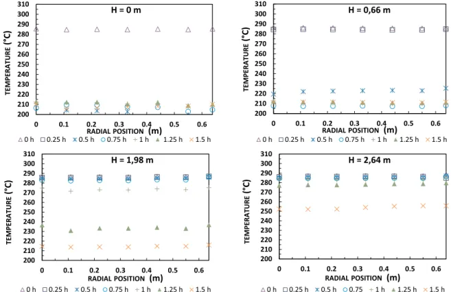
A.1. Experimental radial temperature distribution
The radial temperature distribution in this experimental setup was evaluated each 15 min for alumina spheres at four axial locationsFig. 1(at the bottom and top of first and last basket).Fig. 9shows that during the charging process, there is no significant temperature variation between the thermocouples, where position (0 m) represents the center of the thermocline, and location (0.64 m) is at the thermocline's wall. Similarly,Fig. 10presents minimal temperature fluctuation in the radial temperature distribution during discharge. This finding validates the 1D thermal behavior of thermocline TES during charge and discharge operation. However, Fasquelle et al.[51]noted that radial temperature variation is more prominent during standby mode.
Fig. 9. Radial temperature evolution during charge at four axial reference positions.
A.2. Model Validation
Model validation evaluates the accuracy of the model predictions against temperature readings from the thermocouples.Fig. 11plots the non-dimensional temperature profile against non-non-dimensional axial coordinates each 15 min for both model predictions and experimental results. It shows that for alumina spheres, the model accurately predicts the temperatures inside the thermocline during the charge test (a). While for discharge (b), a slight deviation appears at temperatures lower than 20% of the maximum temperature in the thermocline.
Fig. 12(a) exhibits that the model consistently predicts the experimental temperature during charge, except when the temperature was lower than 10% of maximum temperature, where a small mismatch appears.
Fig. 12(b) exhibits very close temperatures profiles during the discharge process between simulated and test results; however, a repetitive minor deviation appears at temperatures close or lower than 10% of maximum temperature.
The model shows a reliable prediction for both materials during charge and discharge tests. A slight variation between experimented and simulated temperatures appears during discharge phases at some thermocouples. This difference is probably due to the uncertainty of reading as well as the position of the thermocouple inside the tank. Hence, the model is valid, as it is consistent with the previous finding by Hoffman et al.[49].
Fig. 11. Non-dimensional temperature profiles for alumina, model against experiment (a) charge (b) discharge.
References
[1] A.M. Abdulateef, J. Abdulateef, A.A. Al-Abidi, K. Sopian, S. Mat, M.S. Mahdi, A combination of fins-nanoparticle for enhancing the discharging of phase-change material used for liquid desiccant air conditioning unite, J. Energy Storage 24 (2019) 100784February.
[2] I. Dincer and R. M. A, Thermal Energy Storage Systems and Applicaations, second ed., WILEY, 2011.
[3] P.A. Galione, C.D. Pérez-Segarra, I. Rodríguez, A. Oliva, J. Rigola, Multi-layered solid-PCM thermocline thermal storage concept for CSP plants. Numerical analysis and perspectives, Appl. Energy 142 (2015) 337–351.
[4] B. chen Zhao, M. song Cheng, C. Liu, Z. min Dai, Thermal performance and cost analysis of a multi-layered solid-PCM thermocline thermal energy storage for CSP tower plants, Appl. Energy 178 (2016) 784–799.
[5] V. Becattini, L. Geissbühler, G. Zanganeh, A. Haselbacher, A. Steinfeld, Pilot-scale demonstration of advanced adiabatic compressed air energy storage, Part 2: tests with combined sensible/latent thermal-energy storage, J. Energy Storage 17 (2018) 140–152.
[6] A. Elouali, et al., Physical models for packed bed: sensible heat storage systems, J. Energy Storage 23 (2019) 69–78 February.
[7] R. Tiskatine, et al., Suitability and characteristics of rocks for sensible heat storage in CSP plants, Sol. Energy Mater. Sol. Cells 169 (2017) 245–257 May.
[8] J.E. Pacheco, S.K. Showalter, W.J. Kolb, Development of a molten-salt thermocline thermal storage system for parabolic trough plants, J. Sol. Energy Eng. 124 (2) (2002) 153–159.
[9] C. Xu, Z. Wang, Y. He, X. Li, F. Bai, Sensitivity analysis of the numerical study on the thermal performance of a packed-bed molten salt thermocline thermal storage system, Appl. Energy 92 (2012) 65–75.
[10] C. Mira-Hernández, S.M. Flueckiger, S.V. Garimella, Numerical simulation of single-and dual-media thermocline tanks for energy storage in concentrating solar power plants, Energy Procedia 49 (2014) 916–926.
[11] A.M. Bonanos, E.V. Votyakov, Sensitivity analysis for thermocline thermal storage tank design, Renew. Energy 99 (2016) 764–771.
[12] J.-.F. Hoffmann, T. Fasquelle, V. Goetz, X. Py, Experimental and numerical in-vestigation of a thermocline thermal energy storage tank, Appl. Therm. Eng. 114 (2017) 896–904.
[13] S. Khare, M. Dell'Amico, C. Knight, S. McGarry, Selection of materials for high temperature sensible energy storage, Sol. Energy Mater. Sol. Cells 115 (2013) 114–122.
[14] A.I. Fernandez, M. Martnez, M. Segarra, I. Martorell, L.F. Cabeza, Selection of materials with potential in sensible thermal energy storage, Sol. Energy Mater. Sol. Cells 94 (10) (2010) 1723–1729.
[15] D. Barlev, R. Vidu, P. Stroeve, Innovation in concentrated solar power, Sol. Energy Mater. Sol. Cells 95 (10) (2011) 2703–2725.
[16] S. Kuravi, J. Trahan, D.Y. Goswami, M.M. Rahman, E.K. Stefanakos, Thermal energy storage technologies and systems for concentrating solar power plants, Prog. Energy Combust. Sci. 39 (4) (2013) 285–319.
[17] M. Medrano, A. Gil, I. Martorell, X. Potau, L.F. Cabeza, State of the art on high-temperature thermal energy storage for power generation. Part 2-Case studies, Renew. Sustain. Energy Rev. 14 (1) (2010) 56–72.
[18] X. Py, et al., Recycled material for sensible heat based thermal energy storage to be used in concentrated solar thermal power plants, J. Sol. Energy Eng. 133 (3) (2011) 031008.
[19] A. Gutierrez, et al., Advances in the valorization of waste and by-product materials as thermal energy storage (TES) materials, Renew. Sustain. Energy Rev. 59 (2016) 763–783.
[20] N. Lopez Ferber, et al., Ceramics from municipal waste incinerator bottom ash and wasted clay for sensible heat storage at high temperature, Waste Biomass Valorization 0 (0) (2019) 0.
[21] T. Fasquelle, Q. Falcoz, P. Neveu, G. Flamant, J. Walker, Compatibility tests be-tween Jarytherm?? DBT synthetic oil and solid materials from wastes, AIP Conf. Proc. 1734 2016.
[22] F. Motte, Q. Falcoz, E. Veron, X. Py, Compatibility tests between solar salt and thermal storage ceramics from inorganic industrial wastes, Appl. Energy 155 (2015) 14–22.
[23] A. Meffre, X. Py, R. Olives, C. Bessada, E. Veron, P. Echegut, High-Temperature sensible heat-based thermal energy storage materials made of vitrified MSWI fly ashes, Waste Biomass Valorization 6 (6) (2015) 1003–1014.
[24] A. Faik, J. Rodríguez-Aseguinolaza, I. Ortega-Fernández, B. D'Aguanno, A. Gil, N. Calvet, Thermophysical characterization of a by-product from the steel industry to be used as a sustainable and low-cost thermal energy storage material, Energy 89 (2015) 601–609.
[25] L. Miró, M.E. Navarro, P. Suresh, A. Gil, A.I. Fernández, L.F. Cabeza, Experimental characterization of a solid industrial by-product as material for high temperature sensible thermal energy storage (TES), Appl. Energy 113 (2014) 1261–1268. [26] S. Ushak, A. Gutierrez, H. Galleguillos, A.G. Fernandez, L.F. Cabeza, M. Grágeda,
Thermophysical characterization of a by-product from the non-metallic industry as inorganic PCM, Sol. Energy Mater. Sol. Cells 132 (2015) 385–391.
[27] J. Gasia, et al., Thermal performance evaluation of bischofite at pilot plant scale, Appl. Energy 155 (2015) 826–833.
[28] a. Meffre, R. Olives, X. Py, C. Bessada, P. Echegut, U. Michon, Design and industrial elaboration of thermal energy storage units made of recycled vitrified industrial wastes, Vol. 4 Energy Syst. Anal. Thermodyn. Sustain. Combust. Sci. Eng. Nanoeng. Energy, Parts A B, 2011, pp. 757–762.
[29] A. Kere, N. Sadiki, X. Py, V. Goetz, Applicability of thermal energy storage recycled ceramics to high temperature and compressed air operating conditions, Energy Convers. Manag. 88 (2014) 113–119.
[30] X. Py, N. Calvet, R. Olives, P. Echegut, C. Bessada, F. Jay, Thermal storage for solar power plants based on low cost recycled material, EFFSTOCK, the 11th International Conference on Thermal Energy Storage, 3 2009.
[31] N. Pfleger, T. Bauer, C. Martin, M. Eck, and A. Wörner, “Thermal energy storage – overview and specific insight into nitrate salts for sensible and latent heat storage,” pp. 1487–1497, 2015.
[32] N. Calvet, et al., Compatibility of a post-industrial ceramic with nitrate molten salts for use as filler material in a thermocline storage system, Appl. Energy 109 (2013) 387–393.
[33] T. Fasquelle, Q. Falcoz, P. Neveu, J. Walker, G. Flamant, Compatibility study be-tween synthetic oil and vitrified wastes for direct thermal energy storage, Waste Biomass Valorization 8 (3) (2017) 621–631.
[34] Y. Lalau, X. Py, A. Meffre, R. Olives, Comparative LCA between current and alter-native waste-based tes for CSP, Waste Biomass Valorization 7 (6) (2016) 1509–1519.
[35] A. Meffre, N. Tessier-Doyen, X. Py, M. Huger, N. Calvet, Thermomechanical char-acterization of waste based TESM and assessment of their resistance to thermal cycling up to 1000 °C, Waste Biomass Valorization 7 (1) (2016) 9–21. [36] F. Motte, S.L. Bugler-Lamb, Q. Falcoz, X. Py, Numerical study of a structured
thermocline storage tank using vitrified waste as filler material, Energy Procedia 49 (2013) 935–944.
[37] I. Ortega-Fernández, J. Rodríguez-Aseguinolaza, Thermal energy storage for waste heat recovery in the steelworks: the case study of the REslag project, Appl. Energy 237 (2018) 708–719 September2019.
[38] J. Felinks, et al., Particle-particle heat transfer coefficient in a binary packed bed of alumina and zirconia-ceria particles, Appl. Therm. Eng. 101 (2016) 101–111. [39] R. Anderson, S. Shiri, H. Bindra, J.F. Morris, Experimental results and modeling of
energy storage and recovery in a packed bed of alumina particles, Appl. Energy 119 (2014) 521–529.
[40] T. Fasquelle, Q. Falcoz, P. Neveu, J.F. Hoffmann, A temperature threshold eva-luation for thermocline energy storage in concentrated solar power plants, Appl. Energy 212 (2018) 1153–1164 January.
[41] R. Anderson, L. Bates, E. Johnson, J.F. Morris, Packed bed thermal energy storage: a simplified experimentally validated model, J. Energy Storage 4 (2015) 14–23. [42] S.M. Flueckiger, S.V. Garimella, Second-law analysis of molten-salt thermal energy
storage in thermoclines, Sol. Energy 86 (5) (2012) 1621–1631.
[43] K.S. Reddy, V. Jawahar, S. Sivakumar, T.K. Mallick, Performance investigation of single-tank thermocline storage systems for CSP plants, Sol. Energy 144 (2017) 740–749.
[44] B. chen Zhao, M. song Cheng, C. Liu, Z. min Dai, Cyclic thermal characterization of a molten-salt packed-bed thermal energy storage for concentrating solar power, Appl. Energy 195 (2017) 761–773.
[45] G. Zanganeh, A. Pedretti, S.A. Zavattoni, M.C. Barbato, A. Haselbacher, A. Steinfeld, Design of a 100 MWhth packed-bed thermal energy storage, Energy Procedia 49 (2013) 1071–1077.
[46] G. Zanganeh, A. Pedretti, A. Haselbacher, A. Steinfeld, Design of packed bed thermal energy storage systems for high-temperature industrial process heat, Appl. Energy 137 (2015) 812–822.
[47] L. Geissbühler, et al., Analysis of industrial-scale high-temperature combined sen-sible/latent thermal energy storage, Appl. Therm. Eng. 101 (2) (2015) 657–668. [48] Z. Liao, et al., Efficiency analyses of high temperature thermal energy storage
systems of rocks only and rock-PCM capsule combination, Sol. Energy 162 (2017) 153–164 January2018.
[49] J.F. Hoffmann, T. Fasquelle, V. Goetz, X. Py, A thermocline thermal energy storage system with filler materials for concentrated solar power plants: experimental data and numerical model sensitivity to different experimental tank scales, Appl. Therm. Eng. 100 (2016) 753–761.
[50] A. Jeanjean, R. Olives, X. Py, Selection criteria of thermal mass materials for low-energy building construction applied to conventional and alternative materials, Energy Build. 63 (2013) 36–48.
[51] T. Fasquelle, “PhD Thesis: Modelisation Et Caracterisation Experimentale D'une Boucle Solaire Cylindro-Parabolique Integrant Un Stockage De Type Thermocline,” Universite De Perpignan Via Domitia, 2017.
[52] T. Fasquelle, Q. Falcoz, P. Neveu, F. Lecat, N. Boullet, G. Flamant, Operating results of a thermocline thermal energy storage included in a parabolic trough mini power plant, AIP Conf. Proc. 1850 2017.
[53] Z.S. Chang, X. Li, C. Xu, C. Chang, Z.F. Wang, The design and numerical study of a 2 MWh molten salt thermocline tank, Energy Procedia 69 (2015) 779–789. [54] H. Agalit, N. Zari, M. Maalmi, M. Maaroufi, Numerical investigations of high
temperature packed bed TES systems used in hybrid solar tower power plants, Sol. Energy 122 (2015) 603–616.
[55] M. MUNRO, Evaluated material properties for a sintered alpha-Alumina, J. Am. Ceram. Soc. 80 (8) (2005) 1919–1928.
[56] T. Esence, A. Bruch, S. Molina, B. Stutz, J.F. Fourmigué, A review on experience feedback and numerical modeling of packed-bed thermal energy storage systems, Sol. Energy 153 (2017) 628–654.
[57] W. Yaïci, M. Ghorab, E. Entchev, S. Hayden, Three-dimensional unsteady CFD si-mulations of a thermal storage tank performance for optimum design, Appl. Therm. Eng. 60 (1–2) (2013) 152–163.
[58] P. Li, B. Xu, J. Han, Y. Yang, Verification of a model of thermal storage incorporated with an extended lumped capacitance method for various solid-fluid structural combinations, Sol. Energy 105 (2014) 71–81.
[59] N. Wakao, S. Kaguei, T. Funazkri, Effect of fluid dispersion coefficients particle-to-fluid heat transfer coefficients in packed beds, Chem. Eng. Sci. 34 (3) (1978) 325–336.
[60] P. Li, J. Van Lew, W. Karaki, C. Chan, J. Stephens, Q. Wang, Generalized charts of energy storage effectiveness for thermocline heat storage tank design and
calibration, Sol. Energy 85 (9) (2011) 2130–2143.
[61] T.R. Davenne, S.D. Garvey, B. Cardenas, M.C. Simpson, The cold store for a pumped thermal energy storage system, J. Energy Storage 14 (2017) 295–310.
[62] Z. Yang, S.V. Garimella, Thermal analysis of solar thermal energy storage in a molten-salt thermocline, Sol. Energy 84 (6) (2010) 974–985.
![Fig. 1. Thermocline tank size and thermocouple positions [52].](https://thumb-eu.123doks.com/thumbv2/123doknet/12278826.322282/4.892.193.691.728.1082/fig-thermocline-tank-size-thermocouple-positions.webp)