PROGRESS IN THE MODELIZATION OF LIGHT
REFLECTION FOR LIGHTING CALCULATIONS
E
MBRECHTSJ.J.
ABSTRACT
A light reflection model for lighting calculations using non-diffuse surfaces has been recently developed. This model is briefly recalled. Then, some improvements are described : investigations in the spectral domain, modifications to the shadowing/masking factor, analysis of the effect of backscattering for very rough surfaces and extension to non-gaussian surfaces.
Keywords : calculations, reflection, radiance factor
1. INTRODUCTION
A general model for light reflection has been proposed in previous publications [1,2]. This model is formulated for lighting applications and, more specifically, for lighting simulation programs. The luminance factor β(θ1,θ2,φ) of any reflecting surface is expressed as a function of the angle of incidence θ and the angles of scattering 1
) ,
(θ2 φ which are defined in figure 1:
) 1 ( )) ( 1 ( )) ( 1 ( cos ) tan exp( cos cos ) , , ( ) ( 2 sin ) ( ) ( 2 ) ( ) , , ( 2 1 4 2 2 2 1 2 1 1 2 1 1 2 1 v surf surf i s sc s s s C α θ ρ θ ρ α α θ θ φ θ θ δ ρ α θ φ δ θ θ δ π θ ρ α φ θ θ β − − + − + − =
The first term is derived from the coherent intensity reflected by the surface which is only significant for slightly rough surfaces. In this specular term, α is a parameter of the surface s
comprised between 0 and 1 [1], and ρs(θ1)is the Fresnel reflection factor depending on the refractive index “n” of the interface and on the angle of incidence. δ is the Dirac pulse function. ()
The second term of (1) is derived from the incoherent intensity due to the roughness of the surface. It contains a parameter of the surface and a Fresnel reflection factor depending on , which is the local angle of incidence on the facets reflecting specularly from
sc α i δ 1 kr to k2 r (fig.1). It also contains a shadowing/masking factor
) , , (θ1 θ2 φ
C depending on a roughness parameter of the surface “s”. The last factor of this second term has been derived assuming a gaussian statistical distribution of the amplitude variations of the surface. The angle α is the angle between the normal to the “specular” facets and the vector
z 1 r
normal to the mean plane of the corrugations. Finally, the third term comes from the intensity reflected by the volume of the material. It contains a parameter of the material called α , v
whereas is the total reflection factor of the surface for an angle of incidence
) (θ
ρsurf
θ . It is defined in [1] as the integral of the two first term of (1) on the variables (θ2,φ). +X -Y -X k 1 θ 1 θ 2 k 2 +Y φ x 1 y 1 z 1
Figure 1 : Definition of the incidence and scattering angles and vectors.
In this expression (1) of the general model, any surface or any object reflecting light is characterised by five parameters : the refractive
PROGRESS IN THE MODELIZATION OF LIGHT REFLECTION FOR LIGHTING CALCULATIONS-EMBRECHTS J.J.
index “n”, the roughness parameter “s” and the three amplitude parameters α , s αsc and α . v
2. SPECTRAL MODELIZATION
Spectroradiometric measurements have been carried out to investigate the assumption that the spectral dependence of the radiance factor is limited to the volume contribution for non-metallic materials, and more particularly to the parameter
v
α . The small spectral dependence in the surface contribution due to the refractive index “n” is not significant for most non-metallic materials.
The spectral radiance factors of some coloured samples have been measured, for several directions of incidence and scattering. In these experiments, the surface and volume contributions are separated by polarization. The comparisons of the measurements with the general model of reflection have shown that :
- the volume contribution has a spectral dependence which is nearly the same for all directions of incidence and scattering;
- the surface contribution is almost independent on wavelength for non-metallic materials, in spectral regions where the separation between both contributions is effective and also where the surface contribution is significant.
These first conclusions are in favour of the assumption that only α is responsible for the v
spectral dependence of light reflection, and therefore for the colour of non-metallic materials. 3. SHADOWING/MASKING FACTOR
In the first version of the light reflection model [1,2], the shadowing/masking factor
) , , (θ1 θ2 φ
C was simply expressed by the product
) ( ) (θ1 Cθ2
C ,C(θ) being defined in [1,2] on the basis of theoretical and experimental studies. A first improvement was an expression for the backscattering half-plane, where the shadowing and masking processes are not independent :
{
( ), ( )}
(2) min ) , , (θ1 θ2 φ π Cθ1 Cθ2 C = =The function C(θ) has also been modified :
) 3 ( ) ( 5 . 0 2 ) exp( 1 ) ( 1 2 − ⎟ ⎟ ⎠ ⎞ ⎜ ⎜ ⎝ ⎛ − − + = erfc a a a C π θ
with a=scotθ. This theoretical expression has been taken from Bass and Fuks [3]. It is a little more complex than the initial function C(θ) , but it is consistent with energy conservation and it can be extended for non-gaussian surfaces. For scattering directions outside the plane of incidence, no simple relation has been found in the litterature, and the following has been adopted :
{
}
) 4 ( ) 2 / ( cos ) ( ) ( ), ( min )) ( 1 ( ) ( ) ( ) ( ) , , ( 3 2 1 2 1 2 1 φ φ θ θ φ θ θ φ φ θ θ = − + = K with C C K C C K CThis corresponds to a continuous variation of the shadowing/masking factor between the half-planes of forward and backward scattering. The factor K(φ) is an approximation based on statistical studies operated on gaussian surfaces.
4. ENHANCED BACKSCATTERING AND SECOND-ORDER SCATTERING
Measurements of light reflected by road pavements have shown the enhancement of backscattering for very rough surfaces. This effect has already been reported by other authors : see, for example, [4]. These authors have suggested that this enhancement was due to multiple scattering between surface elements.
At present, an experimental correction to the model (1) has been adopted to take this effect into account. This correction is reported in another communication [5].
In addition, some analysis have been performed on the second-order reflections ”inside” the surface with ray tracing statistics. It is intended to investigate the possible effect of multiple scattering on enhanced backscattering, and perhaps to propose a theoretical correction of the second term of the model (1).
Most results and conclusions about enhanced backscattering have been derived for “perfectly conducting” surfaces characterised by ρs =1. However, for non-metallic surfaces (which is a frequent situation in lighting calculations), second-order reflections depend on terms proportional to
. Therefore, it is not evident that second-order reflections have a significant effect. An expression has been derived for the contribution of
second-2
s
ρ
PROGRESS IN THE MODELIZATION OF LIGHT REFLECTION FOR LIGHTING CALCULATIONS-EMBRECHTS J.J.
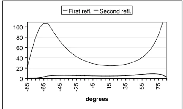
order reflections. This expression is not reported here. Only some significant results of its application are shown in figs.2 and 3. It is seen that:
(
)
) 5 ( , cos 1 cos cos 4 ) , , ( ) ( ) , , ( 1 2 4 2 1 2 1 2 1 ⎟ ⎟ ⎠ ⎞ ⎜ ⎜ ⎝ ⎛ = − = − = = z y z x n n i s q q q q q and k k q with q w C r r r γ α θ θ φ θ θ π δ ρ φ θ θ β ) (γw is the statistical distribution of the slopes - second-order reflections don’t seem to be
highly significant for non-metallic materials. They only become significant if the surface is very rough (s<2) and if the refractive index “n” increases beyond n=1.8, which seems reasonable since Fresnel reflection factors increase with “n”;
γ of the rough surface. If this distribution is gaussian, the second term of (1) is retrieved.
- however, first-order reflections (corresponding to the second term of (1) ) can explain enhanced backscattering at grazing viewing angles, for very rough surfaces (see fig.3). In some cases, second-order reflections also create an enhanced backscattering effect, but this effect is of small amplitude (fig.2).
These first conclusions must of course be confirmed and completed by further investigations.
0 20 40 60 80 100 -85 -65 -45 -25 -5 15 35 55 75 degrees
First refl. Second refl.
0 0.2 0.4 0.6 0.8 1 -85 -65 -45 -25 -5 15 35 55 75 degrees First refl. Second refl.
Figure 3 : Luminance factor (× ) in the plane
of incidence for a rough surface with s=0.75 and n=1.8. Incidence 3 10− ° = 60 1 θ . Surface contribution. REFERENCES
[1] EMBRECHTS J J : Light reflection model for lighting application, Lighting Res.&Technol. 27(4), 231-241, 1995
Figure 2 : Luminance factor ( ) in the plane
of incidence for a rough surface with s=0.25 and n=1.5. Incidence 3 10− × ° = 30 1 θ . Surface contribution.
[2] EMBRECHTS J J: Etude et modélisation de la réflexion lumineuse dans le cadre de l'éclairage prévisionnel (text in english), Collection des Publ. de la Faculté des Sciences Appliquées, N°146 (ISSN 0075-9333), Université de Liège, 1995 5. NON-GAUSSIAN SURFACES
Some differences have been found between measurements and the model (1) for road pavements. A possible explanation would be that the statistical distribution of the surface corrugations is not gaussian. To investigate this, a more general expression for the second term of (1) is now proposed, which will allow to test the model with non-gaussian surfaces :
[3] BASS F G and FUKS J M, Wave Scattering from Statistically Rough Surfaces, Pergamon, Oxford, 1979, chap.7
[4] MACASKILL C, Geometric optics and enhanced backscatter from very rough surfaces,
Jnl. Opt. Soc. Am. A, 8(1), 88-96, 1991
[5] DIJON J M, EMBRECHTS J J and BRUSTEN S, Measurements and modelization of light reflection on road pavement samples, Proceedings
of the 24th Session of the CIE, Warsaw, 1999.
Embrechts J.J , Senior Research Associate at the Belgian National Fund for Scientific Research, Sart-Tilman B28, University of Liège, , B-4000 LIEGE 1 (Belgium)
Tel.:+32 4 3662652, Fax.: +32 4 3662649, e-mail : [email protected]