HAL Id: hal-02152507
https://hal.archives-ouvertes.fr/hal-02152507
Submitted on 11 Jun 2019
HAL is a multi-disciplinary open access
archive for the deposit and dissemination of sci-entific research documents, whether they are pub-lished or not. The documents may come from teaching and research institutions in France or abroad, or from public or private research centers.
L’archive ouverte pluridisciplinaire HAL, est destinée au dépôt et à la diffusion de documents scientifiques de niveau recherche, publiés ou non, émanant des établissements d’enseignement et de recherche français ou étrangers, des laboratoires publics ou privés.
Estimation of the load produced by the electro-thermal
behaviour of lightning strike protection layers on a
composite panel
Audrey Bigand, Christine Espinosa, Jean-Marc Bauchire, Franck Flourens,
Frederic Lachaud
To cite this version:
Audrey Bigand, Christine Espinosa, Jean-Marc Bauchire, Franck Flourens, Frederic Lachaud. Esti-mation of the load produced by the electro-thermal behaviour of lightning strike protection layers on a composite panel. 18th European Conference on Composite Materials (ECCM18), Jun 2018, Athens, Greece. pp.0. �hal-02152507�
an author's https://oatao.univ-toulouse.fr/23471
Bigand, Audrey and Espinosa, Christine and Bauchire, Jean-Marc and Flourens, Franck and Lachaud, Frédéric Estimation of the load produced by the electro-thermal behaviour of lightning strike protection layers on a composite panel. (2018) In: 18th European Conference on Composite Materials (ECCM18), 24 June 2018 - 28 June 2018 (Athens, Greece).
ECCM18 - 18th European Conference on Composite Materials
Athens, Greece, 24-28th June 2018 1
A. Bigand, C. Espinosa, J.M. Bauchire, F. Flourens, F. Lachaud
ESTIMATION OF THE LOAD PRODUCED BY THE
ELECTRO-THERMAL BEHAVIOUR OF LIGHTNING STRIKE PROTECTION
LAYERS ON A COMPOSITE PANEL
A. Biganda,b*, C. Espinosab, J.M. Bauchirec, F. Flourensa, F. Lachaudb
a
Airbus Operations SAS, 316 route de Bayonne, 31060 Toulouse Cedex 9, France b
Université Fédérale de Toulouse MP, Institut Clément Ader CNRS 5312, ISAE-SUPAERO, 3 Rue Caroline Aigle, 31400 Toulouse, France
c
GREMI, Université d’Orléans, 14 Rue d’Issoudun, 45067 Orléans, France
*audrey.a.bigand@airbus.com ; audrey.bigand@isae.fr
Keywords: lightning, damage, carbon fiber reinforced plastics, numerical simulations, phase change
Abstract
The lightning damage mechanism for carbon laminate aeronautical structure is a complex multi-physical phenomenon. The lightning current entering into the surface metallic protection, called LSP (Lightning Strike Protection) and the carbon plies generates Joule heatings and magnetic forces which both induce mechanical forces and surface explosion that has a significant mechanical impact. In this paper, the focus is made on the contribution of the surface explosion. An electro-thermal model of the vaporization profile has been first validated with lightning test results for an accurate dynamic profile. In a second step an overpressure profile combined with the vaporization front has been implemented in a mechanical model. The deflection profiles of the mechanical model are in good correlation with measurements. The contribution of the explosion is the major contributor in the loading of composite panel. A next step will consist in the determination of the contribution of the CFRP (Carbon Fiber Reinforced Plastic) explosion in the first plies which initiates the damage in the composite by breaking the fibers.
1. Introduction
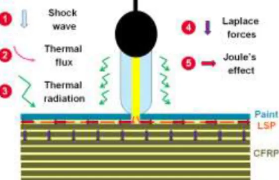
It is today difficult to predict the damage that could be generated by a lightning strike on a composite structure due to its complex phenomenology and the different forces involved [1]. The arc itself generates mechanical force as an acoustic shock wave and thermal constraints as a thermal flux transferred to the panel and thermal radiation from the arc. In addition, the lightning current of 100kA reached in about 20µs flowing into the structure (both lightning metallic protection and composite laminate) generates magnetic force (Laplace force) and Joule heating. The different forces are illustrated in Figure 1:
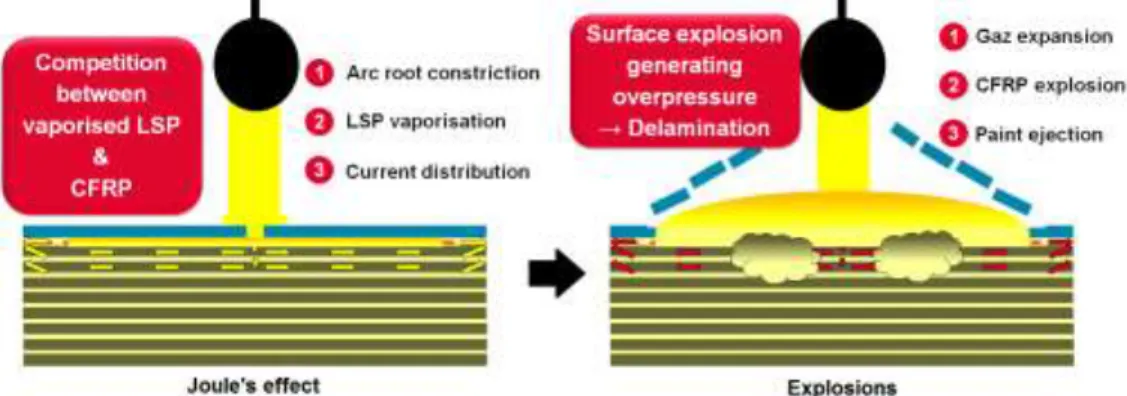
This latest phenomenon leads to a quick elevation of temperature of the LSP up to an explosion phase. The arc constriction due to the presence of a thick paint layer changes the current injection into the LSP and can lead to current injection into the first plies of CFRP that will explode due to Joule heating. The paint is ejected lately due to the gas expansion thus has enhanced the overpressure generated on the surface as presented in Figure 2:
Figure 2 Lightning explosion
This will lead to important delamination into the composite structure in addition to the thermal damage which is important to predict aircraft structure safety.
Most of the works have been focused on the damage generated by a thermal process on bare CFRP panel [2-6], but the reality of the use of CFRP in an aeronautical context is very different.
The complexity of this phenomenon is enhanced by the fact that the damage is not only dependent on the structure configuration but also on the lightning strike protection and the paint thickness which are not part of the sizing of the composite structure against “nominal” stress loads. Indeed, those two parameters are of major importance in the surface explosion generation [7]. A continuous metallic protection like SCF (Solid Copper Foil) will prevent any damage to the composite structure as a shield but usual LSP like ECF (Expanded Copper Foil) is not efficient enough when combined with thick paint configuration.
Figure 3 Lightning Strike Protection principle
For an identical structure and ECF, the increase of paint leads to a significant increase of damage as it increases the overpressure generated on the surface by its confining effect and the amount of current flowing into the CFRP. In
Figure 4
, top section illustrates the increase of visual damage from intact structure when there is no paint to an increase of dry and broken fibers when paint thickness increases. Bottom section illustrates, with the green and blue colors from the ultrasonic scan giving a different echo throughout the plies, the increase of delaminated plies with the increase of paint thickness.ECCM18 - 18th European Conference on Composite Materials
Athens, Greece, 24-28th June 2018 3
A. Bigand, C. Espinosa, J.M. Bauchire, F. Flourens, F. Lachaud
It is therefore important to understand the electrical current distribution impacted by the type of LSP and the paint thickness that will generate the surface explosion in order to create a representative loading on the structure.
2. Vaporisation profile study
Lightning strike generated in laboratory is composed of a first peak of current of about 100kA reached in 17µs defined as waveform D in ED-84 [8]. This sudden and extremely high amount of current generates significant Joule heating in the metallic protection up to vaporization. The vaporization profile is dependent on the material properties and on the current density. For an identical LSP, the vaporization profile will be modified by the presence of paint as it modifies the current injection from the confined plasma.
2.1. Lightning Tests
In order to simplify and decompose this complex phenomenon, specific samples have been manufactured replacing the CFRP panel by an insulating panel made of 11 plies of GFRP (Glass Fiber Reinforced Plastic) of 250µm thick. The purpose of this configuration is to ensure that all the current will flow into the LSP installed on top of panel and focus only on the surface explosion. Indeed, arc root constriction due to paint leads to current injection into the composite when protected with ECF and the modified vaporized area is difficult to determine as illustrated in Figure 5.
Figure 5 Vaporisation profile on CFRP vs GFRP
It is important to noticed that SCF profile is not modified when installed on CFRP which that no current flew into the structure in opposition to ECF. Also, the profile of vaporized ECF is not a diamond shape as shown in Figure 4 when the arc is free but more symmetric when confined by paint.
2.1.1. Set up
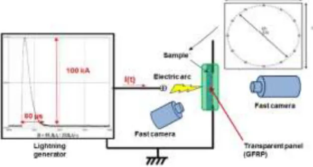
Due to the high luminosity of the electrical arc, it is almost impossible to record the vaporization profile of the LSP. In this set up, the panel is fixed on a circular frame of Ø370mm. The Waveform D current is injected on the front by an electrical arc and high speed camera (1Mfps) is installed on the back to follow the vaporization profile through the transparent panel as presented in Figure 6.
2.1.2. Test results
The contamination of plasma with copper vapor is very bright, this is the reason why it is possible to record its evolution with high speed camera, a simple filter and data picture treatment as illustrated in Figure 7.
Figure 7 Vaporization profile example
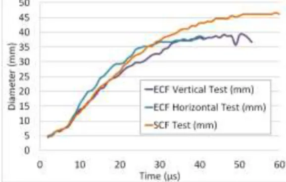
SCF88 (88 gsm) and ECF195 (195gsm) vaporization profiles (both covered by 400µm of paint) are compared in Figure 8. It is important to notice that their profiles are similar up to Ø 35mm which means that current distribution is not only imposed by the material conductivity [9] which is anisotropic for ECF but limited and confined by the paint.
Figure 8 Vaporization profile comparison 2.2. Theory
To study the vaporization profile due to Joule heating, the resolution of the heat equation considering an adiabatic system as defined in equation (1) is necessary:
(1) m is the mass and Cp is the specific heat of the material. The power P is provided by the electrical current flowing into the metallic protection. Above equation is therefore translated for each phase and at the phase change state as defined in equation (2), (3) and (4).
(2)
(3)
(4) The electrical conductivity σ and the specific heat Cp are dependent on the temperature which
significantly increases during the phenomenon. It is important to have those tabulated values that usually available for metallic elements for solid and liquid state. At a first stage, the density ρ is considered constant as macroscopically, the volume doesn’t change in the preliminary stage as the metallic protection is confined by the resin. The enthalpy of fusion ΔHmelt is used to assess the energy
consumed in the phase change. Finally, the electrical current density j depends on the injected current (waveform D), its distribution into the metallic protection but also how the plasma interfaces with it. For this purpose, electro-thermal models have been developed.
ECCM18 - 18th European Conference on Composite Materials
Athens, Greece, 24-28th June 2018 5
A. Bigand, C. Espinosa, J.M. Bauchire, F. Flourens, F. Lachaud 2.3. Model
For isotropic lightning strike protection, a simple 2D axisymmetrical model has been developed with COMSOL in order to predict the vaporization profile of a solid copper foil of 10µm thick, equivalent to SCF88. For anisotropic protection due to their geometrical pattern as ECF, a more complex 3D equivalent foil model has been developed introducing electrical conductivity anisotropy combined to a specific injection model area based on test results presented in 2.1.2.
Figure 9 Vaporisation profile model comparison
In Figure 9, vaporization diameter evolution is well predicted with COMSOL. Anisotropic 3D equivalent model demonstrates already quite good results thanks to the use of tests for injection model but additional arc root interaction models with the paint are planned in order to refine the results.
3. Explosion model
As developed by Soulas [10] and Lepetit [11], a lightning impact could be simulated by an equivalent overpressure. But due to the quick evolution of the loading, it is important to consider time and space evolution to represent lightning mechanical loading and be able to predict the damage distribution. Liu [12] developed an interesting approach by using JWL model in order to generate an explosion but the parameters of the blow-off would need to be determined per surface explosion type.
3.1. Theory
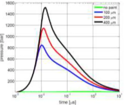
Karch [13] developed several models for the different mechanical loadings due to lightning strike: acoustic shock wave, Laplace forces and surface explosion. This last loading considering the impact of the paint thickness provides the time evolution of the pressure. It is based on a laser shock model combined with an inertial model to take into account the paint impact. This model has been coupled with the vaporization profile developed in the previous chapter which provides the space evolution of the overpressure. In this study, we will focus on ECF195 configuration with 400µm of paint as illustrated in Figure 10:
Figure 10 ECF195 surface explosion pressure
This is a significant overpressure delivered in about 1µs compared to magnetic pressure and acoustic shock wave of about few MPa. This will be the major contributor of the plate deflection in the early stage.
3.2. Lightning test
As presented in 2.1.1, the set up is similar except that, instead of one high speed camera, two cameras are installed on the back of the sample in order to generate deflection profiles by stereocorrelation, with a recording every 3,8µs [14]. The same samples with 11 plies of GFRP covered by ECF or SCF with 400µm of paint have been tested and the deflection in center and the deflection profile on a horizontal section of 80mm in the center of the panel have been recorded. Figure 11 illustrates the deflection of the GFRP panel at several times for SCF and ECF configuration where 0 is the center of the panel on the horizontal section taken. ECF profile is slightly sharper than SCF which doesn’t fully explain the difference in the damage generation. In order to assess this point, fiber breakage due to direct current injection from the plasma shall be added.
Figure 11 Lightning test deflection 3.3. Model
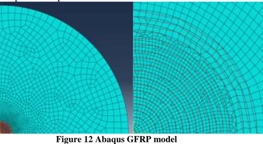
In Abaqus explicit, the GFRP plate has been modeled as a shell without damage model since no delamination has been measured on those panels. Only the area maintained by the circular frame (Ø370mm) has been considered with perfect embedded boundary conditions. A destructured mesh with local refinement on the different injection rings has been built. As presented in Figure 12 each ring is 1mm wide and will be used to apply the surface explosion overpressure defined in 3.1 following the temporal vaporization profile.
Figure 12 Abaqus GFRP model
The rings have been fitted in order to represent the explosion of ECF confined by 400µm of paint. The profiles of deflection at different time up to 100µs, presented in Figure 13, demonstrate a good
correlation between the model and the test results. Upon 100µs the comparison is more difficult since the deflection starts to be bigger than the recording window. This sudden vaporization of the metal is thus the main contributor of the panel deflection.
ECCM18 - 18th European Conference on Composite Materials
Athens, Greece, 24-28th June 2018 7
A. Bigand, C. Espinosa, J.M. Bauchire, F. Flourens, F. Lachaud Figure 13 ECF195 deflection profile comparison
4. Conclusion
Damage generation in composite due to lightning strike is an extremely complex phenomenon which has to be decomposed in order to solve this problem by reasonable steps. This first step has consisted in modelling the surface explosion which is a major parameter in the damage generation. In a simplified approach, specific configurations have been studied in order to ensure surface phenomena only with no interaction to the structure by the use of insulated panels. The dynamic profile of this surface explosion has been first determined through an electro-thermal model based on Joule heating validated by original lightning tests. This spatial vaporization profile has been used in order to load the panel with an explosive overpressure with an evolving radius in a mechanical model. This first approach is presenting promising results. The next step will be to consider this loading on CFRP panels with the combination of fiber breakage due to Joule heating in the first plies and a damage model low in order to predict the delamination.
References
[1] L. Chemartin, P. Lalande, B. Peyrou, A. Chazottes, P.Q. Elias, “Direct Effects of Aircraft Structure: Analysis of the Thermal, Electrical and Mechanical Constraints”, Journal of
Aerospace Lab, Issue 5 (2012)
[2] Chippendale, Richard. “Modelling of the Thermal Chemical Damage Caused to Carbon Fibre Composites.” PhD, University of Southampton, 2013
[3] Dong, Qi, Yunli Guo, Xiaochen Sun, and Yuxi Jia. “Coupled Electrical-Thermal-Pyrolytic Analysis of Carbon Fiber/Epoxy Composites Subjected to Lightning Strike.” Polymer 56 (January 2015): 385–94
[4] Ogasawara, Toshio, Yoshiyasu Hirano, and Akinori Yoshimura. “Coupled Thermal–electrical Analysis for Carbon Fiber/Epoxy Composites Exposed to Simulated Lightning Current.”
Composites Part A: Applied Science and Manufacturing 41, no. 8 (August 2010): 973–81
[5] Wang, Y., and O. I. Zhupanska. “Evaluation of the Thermal Damage in Glass Fiber Polymer-Matrix Composites in Wind Turbine Blades Subjected to Lightning Strike.” In Proceedings of
[6] Wang, F.S., Y.Y. Ji, X.S. Yu, H. Chen, and Z.F. Yue. “Ablation Damage Assessment of Aircraft Carbon Fiber/Epoxy Composite and Its Protection Structures Suffered from Lightning Strike.” Composite Structures 145 (June 2016): 226–41
[7] A. Bigand, Y. Duval, “Quantification of the mechanical impact of lightning strike protection explosion confined by thick paint”, Int. Conf. on Lightning and Static Electricity (Nagoya) 2017.
[8] EUROCAE, “ED-84 - Aircraft lightning environment and related test waveforms”, (July 2013). [9] Rafael Sousa Martins, “Experimental and theoretical studies of lightning arcs and their
interaction with aeronautical materials”, Ph. D. thesis, Université Paris-Saclay (2016).
[10] F. Soulas, C. Espinosa, F. Lachaud, S. Guinard, B. Lepetit, I. Revel, Y. Duval, “A method to replace lightning strike tests by ball impacts in the design process of lightweight composite aircraft panels”, International Journal of Impact Engineering 111 (2018) 165-176.
[11] B. Lepetit, F. Soulas, S. Guinard, I. Revel, G. Peres, “Analysis of composite panel damages due to a lightning strike: mechanical effects”, Int. Conf. on Lightning and Static Electricity (Seattle) 2013.
[12] Liu, Z. Q., Z. F. Yue, F. S. Wang, and Y. Y. Ji. “Combining Analysis of Coupled Electrical-Thermal and BLOW-OFF Impulse Effects on Composite Laminate Induced by Lightning Strike.” Applied Composite Materials 22, no. 2 (April 2015): 189–207
[13] C. Karch, R. Honke, J. Steinwandel, K.W. Dittrich, “Contributions of lightning current pulses to mechanical damage of CFRP structures”, Int. Conf. on Lightning and Static Electricity
(Toulouse) 2015.
[14] F. Lago et al., “Measurement by a digital image correlation technique of the deflection of panels submitted to lightning pulse currents”, Int. Conf. on Lightning and Static Electricity (Oxford) 2011.