Par
Reza Sadat Alhosseini
Mémoire présenté à :
L'Université du Québec à Chicoutimi
Comme exigence partielle de la maitrise en ingénierie
DEVELOPMENT OF AN ARTIFICIAL NEURAL NETWORK (ANN) MODEL FOR ESTIMA TING CEMENTED PAS TE BACKFILL PERFORMANCE
AVRIL 2009
Ce mémoire a été réalisé a l'Université du Québec en Abitibi-Témiscamingue (UQAT) dans le cadre du programme de maitrise en Ingénierie de l'Université du Québec a
Mise en garde
La bibliothèque du Cégep de l’Témiscamingue et de l’Université du Québec en Abitibi-Témiscamingue a obtenu l’autorisation de l’auteur de ce document afin de diffuser, dans un but non lucratif, une copie de son œuvre dans Depositum, site d’archives numériques, gratuit et accessible à tous.
L’auteur conserve néanmoins ses droits de propriété intellectuelle, dont son droit d’auteur, sur cette œuvre. Il est donc interdit de reproduire ou de publier en totalité ou en partie ce document sans l’autorisation de l’auteur.
RÉSUMÉ
L'utilisation de la technologie des remblais numers en pâte cimenté est devenue une pratique courante dans les opérations minières modernes. Cependant, l'optimisation de la recette est capitale pour satisfaire les contraintes techniques d'exploitation (propriétés mécaniques) et en même temps pour garantir une utilisation économique et sécuritaire de tels matériaux. Par ailleurs, cette optimisation de recette se fait souvent sur la base de batteries de tests expérimentaux en laboratoire qui sont couteux, demandent du temps et quelque fois difficiles à mettre en œuvre. Dans ce travail, les réseaux de neurones artificiels (RN As) sont testés afin de développer un modèle prédictif pour l'estimation des résistances ciblées. Les RN As se basent sur des paramètres d'entrée qui sont dans notre cas la granulométrie, le teneur en sulphate dans l'eau de mélange, la recette de liant et le temps de cure. Plus de 600 échantillons on été nécessaire pour mener a bien une batterie de tests laboratoire utilisant la silice broyée comme rejet minier. Ceci dans le but de bien contrôler les principaux paramètres affectant la résistance mécanique. Le travail a permis d'obtenir un modèle global et l'approche développée et testée montre que la corrélation entre les valeurs prédites et celles obtenues est excellente
Mots-clés : Environnement numer, remblai cimenté en pâte, compresswn uniaxiale, réseaux de neurones artificiels.
ABSTRACT
Paste backfilling becomes a world wide attractive technology used by most modern underground mining industries. However, optimizing the recipe of paste backfill is of utmost importance to reach the technical requirements (the needed mechanical properties) and at the same time it ensures that the safeness and economical purposes are satisfied. Moreover, achieving this optimization on the basis of the only experimental laboratory testing could be expensive, time consuming and in sorne cases difficult to succeed. In addition, these studies are often affected by subjectivity. In this work, Artificial Neural Networks (ANNs) are tentatively applied for developing predictive models to estimate needed strength values. The ANN s are based on the input parameters of grain size distribution, sulphate content, binder recipe and curing time. In this work, to provide the input data for the neural networks, more than 600 samples were carried out by using silica as artificial tailings. Silica was used in this work to weil control the main tailings properties effects on the UCS and to obtain a global mode!. The approach developed and tested in this study shows that the correlation between the predicated and achieved strength of the pas te backfill is excellent.
KEYWORDS: Mining environment, cemented paste backfill, unconfined compressive strength, artificial neural networks.
ACKNOWLEDGMENTS
I would like to first acknowledge my advisor Dr. M. Benzaazoua and my co advisor Dr. T. Belem for supporting me. This thesis would not have been possible without their constant guidance.
I give special thanks to the faculty, staff and students in the department of Engineering at the University of Quebec in Abitibi-Temiscamingue for their support, in particular: Dr. Erchiqui, Dr. Kandi! and Dr. Koubaa.
I am also indebted to Erol Yilmaz for his help during my study.
My thanks extended to Brian Will. It's a pleasure working with you at Wyeth Organic.
Table of Content RÉSUMÉ ... ! ABSTRACT ... II ACKNOWLEDGMENTS ... III Table of Content ... IV List of Tables ... VI List of Figures ... VII
Introduction ... 1
CHAPTER 1. Literature review on the backfill ... 4
1.1. Introduction ... 4
1.2. Wh y mine fil!? ... 5
1.2.1. Waste disposai ... 6
1.2.2. Excavation exposure ... 6
1.2.3. Sulphide reactivity limitation and metal fixation ... 7
1.3. Backfill performance and Measurement of mechanical strength ... 8
1.4. Types of backfill used in underground mines ... 10
1.4.1. Hydraulic fil! ... 11
1.4.2. Rockfill ... 12
1.4.3. Paste backfill ... 13
1.5. Basic paste backfill material ... 15
1.5.1. Tailings ... 16
1.5.2. Water ... 19
1.5.3. Binder ... 19
CHAPTER 2. Optimization and predictive methods for backfill properties ... 22
2.1. Introduction ... 22
2.2. Statistical methods ... 25
2.2.1. Experimental studies ... 26
2.2.2. Design of experiments ... 27
2.3. Predictive modeling and Regression techniques ... 30
2.4. Artificial Neural Networks ... 35
2.4.1. Inputs ... 36
2.4.2. Transformation functions with weight and summations ... 36
2.4.3. Learning ... 37
2.5. Conclusion ... 38
CHAPTER 3. Problem statement, results, interpretation and discussion ... 39
3.1. Introduction ... 39
3 .2. Material ... 40
3.2.1. Tailings like material ... 41
3 .2.2. Binding agent ... 44
3.2.3. Mixing water ... 44
3.2.4. Artificial paste backfill preparation ... 45
3.3. Method ... 48
3.3.1. Unconfined compression tests ... 48
3.4. Mode! development of Artificial Neural Networks (ANNs) ... 48
3.4.1. Artificial Neuron (node)-Mathematical aspects ... 49
3.4.2. Structure of Multi-Layered perception type ANN ... 50
3.4.3. Network training ... 50
3.5. Experimental Results ... 52
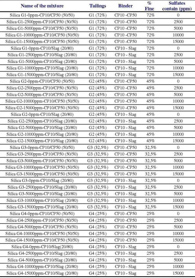
3.5.1. Database obtained ... 52
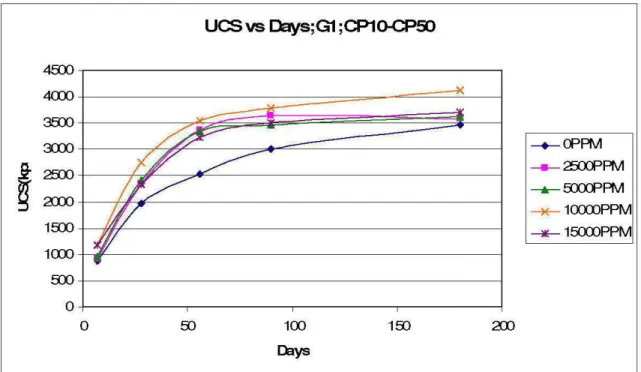
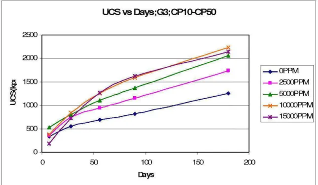
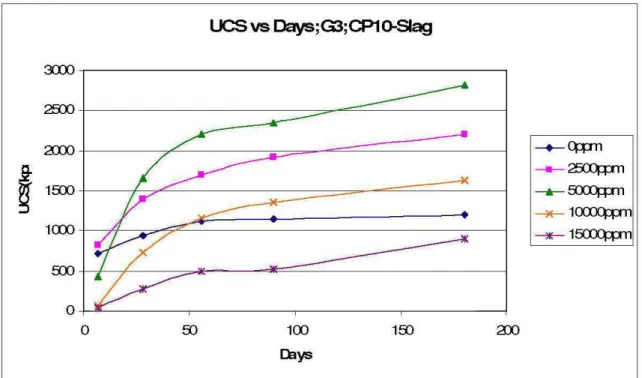
3.5.2. Time dependant backfill performance ... 58
3.5.3. Influence of binder on backfill ... 63
3.5.4. Effect of fine parti cl es content on strength properties ... 65
3.5.5. Effect of sulphate concentration on strength properties ... 71
Conclusion ... 80
List of Tables
Table 1: Property Comparison of the Principal Backfilling Methods ... 15
Table 2: Effect of Parti cie Shape ... 17
Table 3: Particle Characteristic of Silica Powder ... 42
Table 4: Sulfate Concentration and Related Mass of FeSo4,7H2o ... 45
Table 5: Mixture Applied in this Work ... 47
Table 6: UCS for 7 Da ys, 4.5% binder and 75,65% solid ... 53
Table 7: UCS for 28 Days, 4.5% binder and 75,65% solid ... 54
Table 8: UCS for 56 Days, 4.5% binder and 75,65% solid ... 55
Table 9: UCS for 90 Days, 4.5% binder and 75,65% solid ... 56
List of Figures
Figure1: Diagram showing a breakdown of mining methods according to the mine
regional support system used, Brady and Brown (2004) ... 6
Figure 2: Mohr Failure Locus ... 9
Figure 3: The flow chart showing a simplified design chart for underground mine design ... TI Figure 4: The structure of the system analysis software developed by Gunduz (1992) ... 24
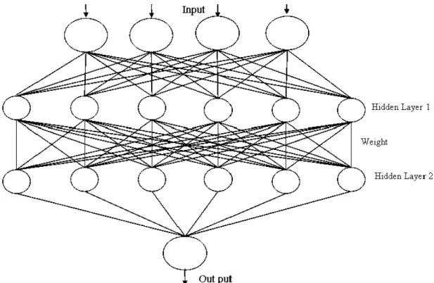
Figure 5: Structure of multi-layered type artificial neural network ... 36
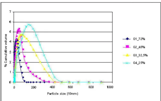
Figure 6: Parti cie size distribution of the silica products ... 42
Figure 7: Particle size distribution curves ... 43
Figure 8: Histogram of Particle size distributions of the silica powder ... 43
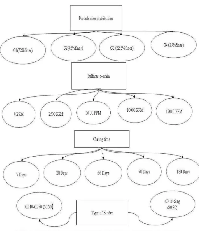
Figure 9: Chemical and physical factors which were considered to prepare laboratory samples ... 46
Figure 10: Simplified diagram of unconfined compression test to obtain UCS value ... 48
Figure 11: Mathematical mode! of an ANN neuron ... 49
Figure 12: UCS vs Days for 72% fine particles; CP10:CP50 ... 59
Figure 13: UCS vs Days for 45% fine particles; CP10:CP50 ... 59
Figure 14: UCS vs Days for 32% fine particles; CP10:CP50 ... 60
Figure 15: UCS vs Days for 25% fine particles; CP10:CP50 ... 60
Figure 16: UCS vs Days for 72% fine particles; CP10: Slag ... 61
Figure 17: UCS vs Days for 45% fine particles; CP10: Slag ... 61
Figure 18: UCS vs Days for 32% fine particles; CP10: Slag ... 62
Figure 19: UCS vs Days for 25% fine particles: CP10: Slag ... 62 Figure 20: UCS according to the content sulfates for the CP1 O-CP50 and CP1 0-Slag (7
~~=~···~ Figure 21: UCS according to the content sulfates for the CP1 O-CP50 and CP1 0-Slag (28 ~~=~···~ Figure 22: UCS according to the content sulfates for the CP1 O-CP50 and CP1 0-Slag (56 ~~=~···M
Figure 23: UCS according to the content sulfates for the CP1 O-CP50 and CP1 0-Slag (56 ~~=~···M Figure 24: UCS according to the content sulfates for the CP1 O-CP50 and CP1 0-Slag (180 ~~=~···~
Figure 25: UCS vs Parti cie size; CP1 O:CP50; 7 da ys ... 65
Figure 26: UCS vs Parti cie size; CP1 O:CP50; 28 da ys ... 66
Figure 27: UCS vs Parti cie size; CP1 O:CP50; 90 da ys ... 66
Figure 28: UCS vs Particle size; CP10:CP50; 90 days ... 67
Figure 29: UCS vs Particle size; CP10:CP50; 180 days ... 67
Figure 30: UCS vs Particle size; CP10: Slag; 7 days ... 68
Figure 31: UCS vs Particle size; CP10: Slag; 28 days ... 69
Figure 32: UCS vs Particle size; CP10: Slag; 56 days ... 69
Figure 33: UCS vs Particle size; CP10: Slag; 90 days ... 69
Figure 34: UCS vs Particle size; CP10: Slag; 180 days ... 70
Figure 35: UCS vs Sulfate content; CP10:CP50; 7days ... 71
Figure 36: UCS vs Sulfate content; CP1 O:CP50; 28 da ys ... 71
Figure 37: UCS vs Sulfate content; CP1 O:CP50; 56 da ys ... 72
Figure 38: UCS vs Sulfate content; CP10:CP50; 90 days ... 72
Figure 39: UCS vs Sulfate content; CP10:CP50; 180 days ... 73
Figure 40: UCS vs Sulfate content; CP10: Slag; 7 days ... 74
Figure 41: UCS vs Sulfate content; CP10: Slag; 28 days ... 74
Figure 42: UCS vs Sulfate content; CP10: Slag; 56 days ... 74
Figure 43: UCS vs Sulfate content; CP1 0: Slag; 90 da ys ... 75
Figure 44: UCS vs Sulfate content; CP1 0: Slag; 180 da ys ... 75
Figure 45: Neural networ k inputs and output ... 77
Figure 46: Evaluation of the ANN performance ... 77
Introduction
In the practice of underground mining, cemented backfill has become more important with the development of large scale bulk mining methods. In wet mill tailings, cement and water are mixed and delivered into underground stop opening by pipelines. The cured fil! then may support the rock walls when an adjacent pillar is recovered (Potvin et al, 2005). Stability of mine backfill is necessary for maximum ore recovery, for safe working conditions and for underground and environmental concerns. The mechanical and rheological properties of cemented paste backfill depends on physical, chemical, and mineralogical properties of the mine tailings, binder types and their proportions, and chemistry as weil as proportion of type mixing water (Benzaazoua et al, 2002).
Generally, backfill stability increases with the binder proportion. Thus, a more stable backfill can be obtained by adding more binder (Hassani et Archibald, 1998). However, due to the fact that backfill cement costs are a significant part of the operating costs in large underground mines, the use of cement should be minimized. A high quality backfill should use minimum binder and be capable of maintaining its stability during the mining process of adjacent pillar recovery (Pal! et al, 2007). In many practical cases, mine engineers have to choose the best recipe, which provides the desired Unconfined Compressive Strength (UCS) with optimum cost, out of a number of alternatives. U suai! y, this number is significant; the decision should be based on an indirect estimation by empirical equations. If it is small, the decision may be based on the comparison analysis. Both methods are time consuming, expensive, and allocated. Then, it has been necessary to apply machine learning methods to optimize the recipe and predict the performance.
Few different ways are available to determine sorne mechanical parameters such as modulus of elasticity
(E)
and unconfined compressive strength(ucs)
of cemented paste backfill (CPB ). For example, Regression- Causal methods have been previously developed for UCS forecasting (Wang et al, 2007). Thus, based on a battery of experimental tests, the authors have established a multiple linear regressive mode! for fil!strength prediction with the help of Matlab software. Moreover, artificial neural networks have been employed for developing predictive models to estimate the needed parameters (Rankine and Sivakugan, 2005).
An artificial neural network (ANN), often called "neural network" (NN), is a mathematical mode! or computational mode! based on biological neural networks. It consists of an interconnected group of artificial neurons that processes information using a connectionist approach to computation. In most cases, an ANN is an adaptive system that changes its structure based on external or internai information that flows through the network during the learning phase (Haykin, 1994).
Rankine and Sivakugan (2005) proved that the correlations between the predicted and achieved strength of the paste for both Cannington mine and paste fil! worldwide using ANN s was excellent. The authors stated that the use of ANN s as part of an integrated planning tool for the design of backfills is very pertinent.
The main objective of this study is to develop an ANN s mode! to predict the pas te backfill performance and study the effects of sorne physical and chemical parameters on the mechanical behaviors of cemented backfill by using artificial tailings. The direct use of mine tailings proves to be hard to study, especially when an individual wants to study few specified parameters among al! of them. For this reason, silica powder is used in this research. It gi v es the power to control and minimize the effects of other mineral compounds presented in the real tailings. The main assumption allowing that tailing grains are not reactive in the condition of paste backfilling. This is weil demonstrated by previous works where sulphide oxidation has been demonstrated as negligible (Ouellet et al, 2005). The methodology of this work is based on two stages: an experimental study which may illustrate the effect of the main chemical and physical properties of tailings (particle size), mixing water (sulphate content) and binder by using silica as simulated tailings. In the second part, the obtained results in terms of unconfined compressive strength (UCS) are used to train and test the implemented neural networks. Then, the obtained network can act as a computer tool to predict the unconfined compressive strength of cemented paste backfill.
The reminder of this work is organized as follows. In chapter 1, a literature review on the backfill is presented. Chapter 2 provides background information on the optimization and prediction models and methods applied for cemented paste backfill. In chapter 3, the experimental apparatus and procedures as weil as experimental results are presented. Also, in chapter 3, it is shawn that the constructed ANN mode! exhibits a high performance for predicting UCS.
CHAPTER 1. Literature review on the backfill
1.1. Introduction
During the last decade, technological advances in ore processing bas increased. As a result of the continuai extraction of high grade ore deposits in the earth' s ernst and development in ore processing, a large volume of waste products including tailings and waste rocks are produced during mining operations.
On the other band, increasing environmentallegislations dictate that waste materials must be treated in an appropriate way. Therefore, the use of cemented paste backfill as an appropriate waste management approach bas increased in the most mines al! around the world (Benzaazoua et al, 2004).
Traditionally, mine tailings were deposited as dilute slurries in large dams. However, it is weil known that dams are at risk of failure due to leakage, instability and liquifaction. To overcome these problems, the best solution is to use dry or half dry disposa! methods such as dry stacking, thickened tailings disposa! and mine backfill.
Mine backfill refers to any material that is used to fil! mine openings for stability, environmental and other economie reasons. Backfilling provides severa! useful fonctions in the mining cycle. For example, backfill is used to improve safety and to increase productivity. In terms of safety, it is used as an engineered structural product to control subsidence, to provide pillar support and to improve ground conditions in deep mines or stressed zones. In other words, backfilling provides an adequate working floor for workers and mine equipment, and also increases productivity by controlling ore dilution (Aitchison et al, 1973). In mining operation, backfilling provides a mean of disposing large quantities of waste products underground away from the surface. Backfill is also used to improve mine ventilation. In a more unique role, backfill is used to establish new mining methods (Annor et al, 1988).
In this chapter, we deal with the identification of potential properties of backfill and we present a comprehensive review of backfill materials, properties, and behaviors from the literature.
1.2. Wh y mine fill?
As mentioned before, the disposa! of tailings is a controversial environmental problem. Early methods such as discharging tailings into ri vers and streams or dumping of coarse dewatered tailings on land are not acceptable anymore.
The best way to deal with tailings is to use them in positive ways such as reprocessing in order to recover additional value or return the coarser fraction of mill tailings underground. Back filling has been used since the beginning of the century in South African mines (Stradling, 1988).
The use of different types of fil! and their specifie functions great! y depends on mining methods, mining strategies and mining sequence.
Brady and Brown (2004) proposed a subdivision of mining methods according to three main categories, Figure 1:
• Unsupported methods; where the voids created are meant to be continuously self-filling with caving material as mining progresses. These include black caving methods where orebodies are undercut to induce caving of the ore. They also include sublevel caving methods where the hanging wall progressively caves to fil! voids produced by ore extraction.
• Naturally supported methods; where pillars are left in place as the main way of controlling the stability of extracted areas. This includes room and pillar methods, often employed in low dipping orebodies. Shrinkage and sorne variations of open stop mining can also rely on naturally supported methods, by using crown and rib pillars to separate stoping blacks. This approach generally yields lower ore recovery and is often practiced in low grade orebodies where the increases in ore recovery does not justify the cost of fil!.
• Artificially supported methods; where fills are used to limit voids exposure so as to not exceed critical stable dimensions. This includes variations of eut and fil! and open stope mining methods. As underground extraction reaches deeper levels, stable void exposure becomes smaller, and reliance on an efficient fills delivery.
Mine fill is generally applicable to artificially supported methods. There are three kinds
of back filling: rock backfill, hydraulic backfill and cemented pas te backfill (CPB).
Underground mmmg methods
naturally supported artificially supported unsupported
1
room and sub leve! and VCR longwall sublevel block
long eut and fil! shnnk stopmg p!llar
hole open stopmg stop mg stop mg cavmg cavmg
Magnitudes of displacement in country rock
Strain energy in near-field rock
Rockmass response to mining
Figurel: Diagram showing a breakdown ofmining methods according to the mine
regional support system used, Brady and Brown (2004)
1.2.1. Waste disposai
Disposai of mining processing wastes, whether land based or into bodies of water, 1s
usually considered as an undesirable consequence of meeting society' s needs for metals and minerais. Environmental disasters associated with the discharge or storage of such wastes can have very important consequences (Aitchison et al, 1973). Then, environmental standards and mine closure requirements are gradually transforming the economies of mine waste disposai. Filling of underground voids is proven to be an environmentally friendly vehicle as well as a cost saving option to permanent disposai of mine waste.
1.2.2. Excavation exposure
The stability of underground excavation is a function of a set of variables including spans, time, and ground conditions. Then, uncovered and large excavations have an increasing risk of collapsing with time. Fill can be used to eliminate this problem. In this
method, fil! acts as a bulking agent and its function is simply to occupy the mining void. If the excavation becomes unstable, loosening material from the excavation boundary is kept in place by fil!, and the rockmass failure is stopped.
As explained before, the application of filling depends on the numng methods. For extraction sequence progressing upward, the fil! mass in the stope below will act as a working floor for the stope above. For extraction sequences such as undercut-and-fill moving downward, fil! may be used as a replacement roof. This is especially appropriate when the ground conditions in the back are deemed unsafe and leaving crown pillars separating stopes is not an option.
The use of fil! to limit excavation exposure can lead to very productive and flexible mining sequences, particularly when mining massive orebodies of reasonable grade. In deep mining conditions, where the in situ stress field is high, the sequence of stope extraction becomes one of the main strategie control measures for managing the effects of mine induced critical stress.
1.2.3. Sulphide reactivity limitation and metal fixation
The mining of certain minerais like gold and nickel is associated with acid drainage problems that can cause long-term impairment to waterways and biodiversity. Also, sorne effluents generated by the metal mining industry contain large quantities of toxic substances, such as cyanides and heavy metals, which cause serious health and environmental impacts.
Acid Mine Drainage (AMD) is formed by uncontrolled bioleaching reactions. Bioleaching is a series of complex geochemical and microbial reactions that occurs when water cornes into contact with pyrite (iron disulfide minerais) for example in coal, refuse, or in the overburden of a mine operation.
Laboratory studies have shawn that sulfuric acid is produced when sulfide minerais are exposed to oxygen and water, but scientists have found that the rate of generation is so slow and it would take decades to oxidize a significant proportion of sulfide. Observations of AMD and other natural systems cl earl y demonstrate that acid production occurs in a short time period, from months to years. This is caused by sorne common
strains of bacteria present in almost al! environments that increase the reaction rate by orders of magnitude.
Once the acid is formed, it leaches to other metals, such as copper, zinc, cadmium, nickel, arsenic, lead, and mercury, from the mineralized vein. High concentrations of these metals are dissolved by the acid and carried away in solution. As the acid solution flows away from the mine, the pH changes and affects the chemistry of the solution and causes different metals to begin to precipitate out of solution.
The underground disposa! of tailings is a significant way to reduce the production of AMD. Ouellet et al (2005) proved that the physical and mineralogical characterization of the CPB and the pore water quality evolution result into deduction in the oxidation rate, which can be related to the high degree of saturation maintained in the paste backfill material.
1.3. Backfill performance and Measurement of mechanical strength
Shear strength is one of the most important properties for cemented fil! s. How a fil! mass will behave when it is exposed during the extraction of the adjacent stope depends on the shear strength of fil!. As explained before, backfill strength is directly attributed to the physiochemical properties such as particle size, binder type, PH, sulpate content and soi! mechanic relationships. In uncommented fills, an apparent (C) results from surface tension forces in pore water that disappears when the fil! is full y dry or full y saturated. In cemented fills, the cementation between particles results in the development of cohesion between particles. If there is no cohesion in a fil! mass, it is not possible to have unsupported vertical faces of fil! mass. However, backfill develops shear resistance through the following mechanisms:
• Frictional resistance between fil! partiel es • Interlocking of fil! particles
• Cohesion or any cementing of fil! particles at the surface or at contact point The total shear resistance of a fil! material can be effective! y represented by the Mohr-Coulomb theory. Mohr -Mohr-Coulomb theory is a mathematical mode! describing the response of brittle materials such as concrete, or paste backfill to shear stress as weil as normal
stress. Most of the classical engineering materials somehow follow this ru le in at !east a portion of the ir shear failure envelope. Generally the theory applies to materials for which the compressive strength far exceeds the. tensile strength (J uvinal, R. and Marshek, K.
1991).
As mentioned above, the total shear resistance of a fil l material can be effectively represented bythe Mohr- Coulomb failure stren ~h equation
·r=a.,tan~+C (1)
The cohesion intercept in a typical Mohar-Coulomb envelope arises due to our representation of the shear stress versus normal stress relationship by a straight line. C is graphically generated and may not be a direct measurement of the strength of cemented bonds as shown in Figure2.
...--.
8.
c:: .Q Cl) Q) ..s::: 0 (_)Mohr Failure Locus
Friction Angle
fjJ
Coulomb F ail ure Locus
Normal Stress{u,.} Figure 2: Mohr Failure Locus
In this work, unconfined compress ion testing is used to define the compressive strength of the samples. By definition, the compressive strength of a material is that value of
unia~ial compressive stress reached when the material fails completely. A cylindrical sample is subjected to a confining stress and a."'\.ially loaded until failure in uniaxial testing. In an unconfined compressive strength test, the sarnp le is subjected to axial
During the test, the axialload and the sample vertical displacement are recorded as is the pore water pressure induced in the sample is also recorded. The results are plotted in a deviator stress versus vertical compressive strain plot (Potvin et al, 2005). It has been proven that the obtained results in the !ab are different from the reality. It is real! y hard to maintain the same physical and mechanical conditions found in an underground stope. Then, the experimental data obtained from mine sites is very important for understanding back fil! behavior as a ground support. Much research has been launched to investigate the backfill behavior in the mine site (Ouellet and Servant, 2000), (Belem et al, 2000) and (Belem et al, 2004). These results are also necessary to develop design criteria for mine fil!. For example, many scientific works demonstrated that the backfill stresses distribution in the horizontal and vertical directions are not equal and strongly depend on the geometry and span of the stope (Aubertin et al, 2003), (Hassani et al, 2004) and (Ouellet and Servant, 2000). Few researchers have tried to investigate the applied pressure of paste backfill. However, they have divided the applied pressure in two different categories (Potvin et al, 2005):
• Backfill acting as a local support would have a pressure less than 10 MPa, • Backfill acting as regional support with a pressure exceeding 100 MPa.
1.4. Types of backfill used in underground mines
There are three kinds of back filling, rock backfill, hydraulic backfill and cemented paste backfill (CPB). The use of backfill can bring sorne advantages:
• To reduce the amount of sulphide-rich tailings on the mine-site surface, reducing potential environmental problems.
• To increase the available ore reserves by acting as secondary pillars support and providing mine stability for equipment.
• To reduce mine operating costs.
• To increase the safety of mine operators.
Mines choose the most suitable backfill system among different types of back filling systems based on:
• Fil! preparation procedure.
• The use of alternative cementing agents. • Backfill transportation and placement. • Desired stability and consolidation.
Mining at greater depths (Canadian mines) are demanding high density backfill and related backfill technologies. These demands have present! y resulted in a growth of usage for cemented back fil!. Then, in the following subsection, we present an overview of the types of backfill.
1.4.1. Hydraulic fil!
Hydraulic fil! is the name given to the class of mine fil! types that are delivered as high-density slurry through boreholes and pipelines to the underground workings. The name is derived from the water -borne delivery method. This may be produced direct! y from coarse sand and/or mill tailings, or by desliming finer tailings with hydrocyclones to meet a nominal standard of < 10% passing lO,u. This widely accepted rule of thumb usually produces an acceptable permeability that ensures a free draining fil!. Target permeabilities of 3 x 1
o-'
ms -l or percolation rates of 60 to 100 mm are usually achievedhr
with these sizing targets. Hydraulic fills should be placed at the highest possible solid density to minimize the amount of the excess transported water that must be drained and pumped to the surface. This is usually in ranges between 70% to 75% solids by weight. Slurry fil! technology has been widely used in mining operations but its efficient application may be limited in modern backfill design. In the following, we review sorne of the advantages and disadvantages of slurry fil! (Hassani et Archibald, 1998).
Advantages:
• Relatively simple to operate and to install with a minimum technical supervision required.
• Ali constituents are controlled at the fil! station which secures the fil! quality and the mixture density.
• Pumping can normal! y be avoided by optimizing the pipeline lay-out. Disadvantages:
• Binder washout.
• Excess water needs to be recovered from stopes and pumped to surface; the placed backfill permeability character is a critical design criterion.
1.4.2. Rockfill
Dry rock fil! is rock waste, surface sands, gravels, or dried tailings. The fil! is either dropped down a raise, or tipped into an open stope by a Load Haul Dump (LHD) or dump trucks. The dry rock fil! is most suited for eut and fil! mining. While slurry fil! or paste fil! can be used to fil! voids and achieve tight filling within stopes, rockfill continues to provide the best strength support and for this reason, it is unlikely to be totally replaced by other types of fil!. In the following, we review sorne of the advantages and disadvantages of rockfill (Hassani et Archibald, 1998).
Advantages:
• Simple preparation system.
• Reduction of waste disposa! on surface.
• High strength can be relatively attained when waste rock is consolidated with cement.
Disadvantage:
• High production and transportation cost.
• Coning of placed rockfill when placed in the stope results in the segregation of coarser material to stope sides and reduces the ability to tight fil! stopes.
• Any tailings produced are only partially utilized. Surface disposais must be considered.
The rock fil! can be modified to suit the mining requirement by:
• Optimization particle size using inclusion of fines or blending materials. • Adding binder such as cement.
• No fines con crete - cement slurry rock fil!.
• Tailings paste added rock fil! that can be reticulated through boreholes and pipe !ines as a true rocky paste fil!.
• RF (Rockfill). Rockfill is made by sized or unsized waste rock, obtained either from surface or underground sources, which is normal! y placed without the use of consolidating materials into underground stopes. Then, regarding the fact that RF remains unconsolidated, it provides limited ground support.
• CRF (Consolidated Rockfill). It consists of sized rockfill aggregate mixed with cement, 5% to 6% by weight of aggregate at a pulp density of 50% to 60%. With use of consolidated rockfill, there is usually no drainage problem, and high fil! quality can often be achieved if materials are placed properly.
• CSRF (Consolidated Sand Rockfill). CSRF is a combination of CRF and sand. It requires higher cement additions in the range of 5-10% by weight. With the use of consolidated sand rockfill, raise layouts become less critical as, CSRF material has relative! y good mobility and it provide less segregation potential than CRF. • CSWF (Consolidated Sand Waste fil!). CSWF is a rockfill. Rock waste can be left
into stopes as ore is mined and consolidated by pouring a cement/sand slurry mixture on top to percolate through the rockfill.
Finally, it is proven that by reducing the porosity of the rock fil! the strength of fil! increasing, for the same leve! of binder content.
1.4.3. Paste backfill
Paste fil! is prepared, retaining more fine particles and dewatered to toothpaste-like consistency. The resulting paste does not drain. To eliminate the risk of subsequent liquefaction and remobilization paste backfill is typically placed at 75% to 80% solid by weight via high pressure boreholes and/or pipelines. Sufficient shear yield stress is required to remobilise paste backfill. Note that the longer the paste is left idle, the greater becomes the yield stress to reinitiate flow. If this yield stress is high, and if there is insufficient energy available to remobilise the paste, the line will become plugged (Revel!, 2002).
The non-segregation behavior of paste materials offers a number of operational and management advantages as an underground filling material su ch as:
• Providing a shorter m1mng cycle due to the earlier development of higher compressive strength.
• Reducing binder consumption for equivalent or better slurry backfill strengths. • Disposing of mining waste materials.
• Creating a fresh work.ing surface. Disadvantages:
• The need for developed dewatering equipment. • The presence of increased pipeline pressure
It is proven that not al! tailings may be used to create paste fil! (Landriault et al, 1996). A paste is a granular material which is mixed with sufficient water to fil! the interstices between the partiel es so that the material behaves as a fluid. In order to form a paste, the water must be retained between the particles and not separated from the mix. Collodial electrical particle charges will bond solid partiel es to water molecules to achieve this, but the colloidal of the granular material must retain enough water to form a paste. The colloidal properties of a material are strongly ruled by particle size. As explained before, in the paste backfill tailings must have at !east 15wt% of fine particles in arder to form paste. However, granular materials with insufficient fines will not be able to retain enough water to form a paste, and will separate into two distinct phases.
A comparison between the properties of slurry fil!, rock fil! and paste fil! is presented in Table 1 (Landriault et al, 1996).
In summary, paste backfill can be used as a substitute for al! other types of underground mine fills. The choice between alternative fills is therefore based on financial and environmental impact.
Table 1: Property Comparison of the Principal Backfilling Methods
Properties Slurry fil! Paste fil! Rock fil!
Placement state 60% to 75% solids 75% to 85% solids Dry
Underground Borehole/pipeline via Borehole/pipeline Raise, mobile equipment, transport system gravity via gravity, can be separate cement system
pumped
Binder application Cemented or Cemented on! y Cemented or uncemented uncemented
Water to cement High w/c ratio, low Low to high w/c Low w/c ratio, higher ratio(w/c) binder strength ratio. Low to high binder strength
binder strength
Placement rate 100 to 200 tonne/hr 50 to 200 tonne/hr 100 to 400 tonne/hr
Slurry seUlement and Stockpile and placement,
Segregation segregation, low No segregation reduced strength and
strength development stiffness
Stiffness Low stiffness Low or high High stiffness if placed
stiffness correct! y
Tight filling Cannot tight fil! Easy to tight fil! Difficult to tight fil! Requires large quantity U suai! y lower Moderate binder Binder quantity
ofbinder quantity of binder quantities
required
Barricades expens!Ve mexpens1 ve . . Not necessary
W ater runoff Excessive water runoff Negligible water No water runoff runoff
Capital costs Low capital cost Higher than slurry Moderate capital costs fil!
Operational costs Low distribution costs; Lowest cost for a High operation costs cemented fil!
1.5. Basic paste backfill material
The use of cemented paste backfill improves ground support by reducing the amount of tailings that have to be sent to surface disposa! facilities. These are sorne of the reasons why CPB is currently receiving more attention than ever before. A survey conducted on
32 mmes showed that 44% of surveyed underground mmes m North America and Australia use CPB as backfilling technology (Benzaazoua et al, 2005).
Then, in this subsection, we try to investigate the properties that affect backfill behaviors, rheological strength and hardened strength. Unfortunately, these properties are often affected by subjectivity and influenced by severa! parameters that can be classified into two main types (Benzaazoua et al, 2002).
• Macroscopic parameters, which include al! phenomena occurring at the scale of a stope filled with paste fil! and its interaction with the adjacent rock;
• Intrinsic parameters, which include al! the parameters related to the three main paste backfill components and their changes during curing process.
As explained before, the strength development within paste backfill depends upon: • The physical, chemical and mineralogical characteristics of tailings;
• Chemistry and the amount of water; • Binder type and proportion.
In the following, we focus on the intrinsic parameters and review sorne of work that demonstrated their effects on the backfill performance.
1.5.1. Tailings
Tailings consist of ground rock and process effluents that are generated in a mme processing plant. Mechanical and chemical processes are used to extract the desired product from the mine ore, and produce a waste stream named as tailings. This process of product extraction is never 100% efficient, nor is it possible to reclaim al! the reusable and expanded processing reagents and chemicals. Even the milling process may add other materials to the tailings stream: cyanide, lime, acid and various agents used to assist in the separation of values from gangue. In addition, other deleterious substance in the tailings stream, for instance sulphides, arsenic and other heavy minerais, may as a result of the processing become unstable. The implication of which should be fully considered in any form of tailing disposa!, including use in fil!.
Tailings can range from fine sand to clay-sized particles. The final sizing depends on the leve! of grinding carried out during processing. The most common means of presenting the sizing is in the form of a cumulative distribution. Particle size of tailings has direct
impact on the micro-structural properties of the CPB. Porosity of CPB has a direct relation with the particle size, which means that fine particle size leads to high porosity and vice versa.
In other words, many researchers demonstrated that porosity, void ratio and degree of saturation is not only related to particle size, but also related to drainage and consolidation conditions. Consolidated and drained CPB leads to lower porosity, void ratio and degree of saturation than unconsolidated and undrained CPB.
Benzaazoua et al, (2002), Hassani and Archibald, (1998) and Fall et al, (2005) presented that coarse and medium tailings produce better strength and stability than fine tailings due to less pore size and porosity. Also, coarse tailings require less water than medium or fine tailings to reach the same pulp density.
The parti cie size of tailings is not on! y an important factor in backfill performance, but is also in terms of backfill transportation, from the backfill plant to the stope, and through the pipelines. It is proven that fine particles less than 20 f1m act as lubricant along the pipe wall, which reduces flow resistance. In fact, coarse particles are naturally forced to the center of the flow (Verkek and Markus, 1998).
The comminution process, for most minerais, produces particles that are angular shaped, and that yield a dense and competent mass. However, sorne minerais produce elongated or platy particles. This can influence sorne properties, such as permeability, density and strength. Flat mineral particles will generally settle more slowly than rounded particles of equal specifie gravity and drainage time, in the case of hydraulic fil!. However, particle shape affects the size of void and connection paths available for holding and transporting fluids (Herget and Korompay 1978). Table 2 presents the relationship between the parti cie shape and friction angles, and packing density.
Table 2: Effect of Particle Shape
Shape and grading Friction angle ( <p)
Losse packing Dense packing
Rounded, uniform 30° 37°
Rounded, weil graded 34° 40 °
Angular, uniform 35° 43 °
There are two different methods available to determine the parti cie size distribution of fil! materials. The first method uses a set of sieves of different apertures, and a set of cyclones. The second method, applied here, uses optical imaging and laser light.
Finally, it is difficult to choose the dividing particle size that will define the fine filling applications. In this work, we apply 20 f1m as the dividing particle size for coarser and finer fractions of tailings.
The chemical and mineralogical properties of tailings have a great impact on the retention, settling and strength development of CPB. Different ore type with different mineral assemblage can result in different fil! properties.
As explained, the mineralogy of tailings can also affect the final strength of paste backfill by influencing chemical reactions that promote strength or produce additional chemical reactions. Other examples of mineral ogy affecting fil! properties include:
• Specifie gravity of minerais which will determine the density of the fil!. • Silica minerais as it can be very abrasive and result in the high pipeline wear. • Sulphides which may results in the breakdown of the hydrated cement in the fil!
over time.
In terms of chemical properties, mill tailings contain pyrites, which is the main source of sulphides. When sulphur is exposed to water and oxygen, it begins to oxidize, generating sulphuric acid and heat. This oxidation is evident as a change of co lors, indicating rusting of the particles. In other words, the pyrite oxidizes and breaks down into ferrous and ferric iron, hydrogenions and sulphate ions. The sulphide ions can combine with existing hydrated NPC to form gypsum and ettringite (Kesimal et al, 2005) and (Ouellet and Hassani, 2002).
It is proven that sulphides may cause the dissolution of calcic phase of binder in CPB. Also, it is shown that high amount of sulphides in the tailings lead to CPB failure, even though they are made with a relative! y high proportion of sulphate-resistance binder. Note that a certain amount of sulphides has a positive effect on the pas te backfill performance. This positive effect may be related to tailings' density and sulphate precipitation.
1.5.2. Water
Many studies have demonstrated that water has great impact on the cemented paste backfill performance. For example, Benzaazoua et al (2004) presented that the water ratio is very important, because it contrais al! of the hydration and precipitation reaction. This contrais al! of the hardening processes within paste fil! materials. Benzaazoua et al (1999) also launched a series of experimental tests. They produced many mixtures for a constant binder type ratio, with a same ratio of municipal (tap) water, lake water and process water. It was observed, over a 28 day curing period, that the paste backfill made by municipal water produced a higher mechanical strength than lake and process water. It was also proven that a decrease in strength (UCS) occurred with an increase in the water content. Mechanical strength development in the paste back fil! is related to appearance of hydrated phase that form the binder matrix of the fine grains from tailings.
The presence of salt in sufficient concentration can also affect the strength development of cemented fil!. During the curing process, large amount of the salt crystallises. The growth of such crystals may inhibit the strength gain of paste backfill by reducing the dispersion of cement.
Laboratory studies by Wang and Villaescusa, (2000) demonstrated that for both tailings and aggregate based fills, increases in salinity leads to deduction of fil! strengths.
1.5.3. Binder
Another significant factor in the mechanical behavior of paste backfill is the type of binder, for both short and long term. Normal! y, cement, pozzolans, or a mixture of both is used in mines.
The most widely used cements are hydraulic cements, which include a fine powder that reacts with water to bind particles together as aggregates, by hardening from a flowable plastic state to a solid. Mitchell and Smith, (1979) reported that the addition of small quantities of cement to classified hydraulic backfill does not alter the initial porosity significantly.
The relationship between strength of backfill and binder content is not linear. Laboratory testing is necessary to define their relationship.
Swan, (1985) determined that the unconfined compressive strength for any given fil! material is related empirically to cement content by:
ucsacc;
36) (2)
Henderson and Lilley, (2001) found that the following relationship fits better to aggregate fills:
( ) 1.54
ucs
"'63~
(3)C, is the volume of cement particles, c is the cement content weight, and n is the porosity.
Pozzolans are defined as materials which contain constituents that will combine with lime at normal temperatures in the presence of water, to form stable insoluble compounds that show cementing properties.
• Coal Ash: Coal ash is a waste derived from the combination of coals in thermal power generation plants. Coal ash consists of fine particles known as fly ash that flow with flue gases and coarser particles, called bottom ash. They are collected at the bottom of the boiler (Hassani et Archibald, 1998). Chemically, fly ash is predominantly oxides of silicon, aluminum and iron, with small amounts of calcium and alkalis. The mean value of particle size distribution of fly ash is around 10 to 15 f1m. There are two types of fly ash: type C, which is produced from the burning of lignite or sub-bituminous coal and has high lime content, and type F, which is produced from the burning of anthracite or coal and has lower lime.
• Slag: Blast furnace slag is a by-product that results from the fusion of fluxing limestone with coke ash and siliceous, and aluminious residues remaining after the separation of the metal from ore. Note that the granulated slag is the glassy,
non- crystalline, granular material resulting from the rapid quenching of molten slag with water.
The selection and use of an alternative binder for mine backfill consolidation is largely controlled by material availability, cost and technical performance with a particular mine' s fil! aggregate.
Benzaazoua and et al (2002) presented that for high sulphide tailings, neither the slag-based binder nor fly ash slag-based binders is effective. However, the sulphate resistance based binder gives good long term strength. In other words, the slag based binder provides the best strength for low and medium sulphide tailings. The two other types of binder produce unacceptable results.
Many studies proved that there is no universal reCJpe for al! mmes to get good performance for their paste backfill. Finally, Benzaazoua et al, (1999) launched other series of tests with sulphide rich tailings to find the binder recipe. The study proved that a mixture of cement type 10 and cement type 50 gives good UCS values, but the best UCS was obtained by cement type 10 and slag. It is important to mention ag ain that the proportion of binder has a sub-linear relationship with the obtained mechanical resistance.
Final! y, the numng operations used to ob tain use fu! minerais from the earth' s ernst inevitably create fair! y huge amount of waste materials, waste rock, and tailings, of which the mine companies must dispose in an acceptable manner. Mine fil! is a new part of the mining operation that provides a safe working environment for mine operators and that stores mill tailings in underground mine openings. In this chapter, the main concepts of backfill have been presented. In arder to understand the mechanical behaviours of back fil!, we reviewed the physiochemical properties of its constituent materials, and their interactions. Sorne weil- known types of backfill were presented as weiL
In the following chapter, we discuss applied methods that optimize the recipe and/or predict the performance of cemented backfill.
CHAPTER 2. Optimization and predictive methods for backfill properties
2.1. Introduction
Currently, nobody can explain al! the phenomena contributing to pastefill hardening. Then, it seems important for mines to do recipe optimization to find the optimal recipe to satisfy technical, environmental and economical constraints before each of the backfill operations (Benzaazoua et al, 2004).
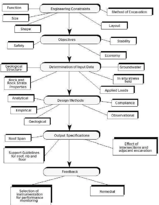
Considering the interaction between the backfill parameters, an integrated design methodology is essential in arder to meet the requirements of mining operations involving backfill. Computers are widely used during the planning and design stages of mining operations. However, there bas been little standardization of hardware and software, and most tasks are covered by individual programs. Usually, a general purpose numerical simulation program is used for the modelling of underground mining activities and these programs can on! y handle one aspect of the design process. Figure 3 shows a flow chart of Bieniawski (1986) which generalizes design charts for underground mines. Gunduz (1992) developed an integrated hydraulic backfill transport simulation module which utilized most of the backfill characteristics data evaluated by material characterisation modules. Figure 3 shows the structure of the system analysis software developed by Gunduz (1995).
FLAC bas been used to develop a mode! capable of demonstrating the excavation, filling, lateral, and vertical earth pressure and loading measures on the backfill (Rankine, 2001) and (Li et al, 2003). Also SEEPW was used to evaluate the flow conditions (Godbout et al, 2004).
Analytical modeling, same as limiting equilibrium analysis, the Overburden method and the Marston were also used for resembling the stress of backfill stope (James et al, 2004). Most of the studies focused on the optimization of CPB properties (Archibald et al, 1995), (Hassani and Archibald, 1998) and (Amaratunge and Yaschyshyn, 1997).
Function Si ze Shape Safety Geological Structure Rock and Rock Strata Properties 1 Analytical
1----Empirical Geological Roof Span Support Guidelînes for roof, rib andHoor Selection of instrumentation for performance m onitoring Melhod of Excavation Lay out Objectives
----1
Stabitity "--...j 1 Economy L _ _ _ ___,Determi nation of Input Data
Design Melhods Output Specifications Feedback Groundwater ln-situ stress field Applied Loads Compliance
l
Observational1
Remediai Effectof intersections and adjacent excavation1
Figure 3: The flow chart showing a simplif ied des ign chart for underground mine design
In order to propose an indirect estimation of CPB properties by empir ical equations , the
statistical methods a.~ traditionally used ( Berry, 1980) , (Saliba, 1996) and (Swan, 1985).System Analysis and Fill Design
in
ining with Backlill
Baokfill System Design and
Ba ok lill Preparation Pro gram s
Support Characterisation of Backfill
Hydraulic Backfill Transport Software
Conoeptual M odels and the De tarrn ination of Geoteohnical Properties of Rock Masses i ;t.ii!d!f.l;j Backfill C haracterisation and Property Database
Geotechnical and N um erioal Simulation Software Program s
FSJI.!t4.M
20-Piane Strain Linear Elastic Bou nd a ry E lem en t Si mulationMJJ.i.!t4.M
20-N on Lin a ar E 1 asto- P 1 as ti o Fin ite E le rn en t Si mulationFigure 4: The structure of the system analysis software developed by Gunduz (1992)
In recent years, new techniques have been applied for developing predictive models to estimate the needed parameters_
For example, Fall et al (2007) applied the response surface methods based modeling to predict the technical and economical performance properti es of the CPB and analysis the interactions between the main components of CBP and their effect on its properties_ Wang et al (2007) developed a multiple linear regressive model for fill strength forecasting by using Matlab software_ They carried out many tests for the ShiZhu Yuan non-ferrous metal mine_ The samples were prepared with different ratio of paste backfill material same as binder ratio, mass fraction and curing time_ The residual examination
proved that the multi-factor regression result is reasonable and reliable. Rankine and Sivakugan (2005) used artificial neural networks (ANNs) to predict and optimize the cost. Applied ANN was based on the input parameters of cement content, solid content, curing time and grain size distribution.
They collected data from various sources and trained the Network by two sets of Data from Cannington mine (PFCAN) and the world wide (PFV AR) samples. To prepare the network two subdivided data were used for modelling and validation respectively.
The obtained coefficient of determination, r2
between the predicted and measured data by this work is 0.901 for world wide mode!.
In this chapter, we present an overview of the definition of statistical techniques, predictive analytics, types of predictive analytics, and artificial neural network.
2.2. Statistical methods
Statistics is a mathematical science pertaining to the collection, analysis, interpretation or explanation, and presentation of data. It is applicable to a wide variety of academie disciplines, from the natural and social sciences to the humanities. Statistics are also used for mak.ing informed decisions in governments and businesses.
In applying statistics to a scientific, industrial, or societal problems, one begins with a process or population to be studied. This might be a population of people in a country, of crystal grains in a rock, or of goods manufactured by a particular factory during a given period. It may instead be a process observed at various times; data collected about this k.ind of "population" constitute what is called a time series.
For practical reasons, rather than compiling data about an entire population, one usually studies a chosen subset of the population, called a sample. Data is collected about the sample in an observational or experimental setting. The data is then subjected to statistical analysis, which serves two related purposes: description and inference.
• Descriptive statistics can be used to summarize the data, either numerically or graphically, to describe the sample. Basic examples of numerical descriptors
include the means and standard deviation. Graphical summarizations include various k.inds of charts and graphs.
• Inferential statistics are used to mode! patterns in the data, accounting for randomness and drawing inferences about the larger population. These inferences may take the form of answers to yes/no questions (hypothesis testing), estimates of numerical characteristics (estimation), descriptions of association (correlation), or modeling of relationships (regression). Other modeling techniques include time series and data mining.
The concept of correlation is particularly noteworthy. Statistical analysis of a data set may reveal that two variables (that is, two properties of the population under consideration) tend to vary together, as if they are connected.
2.2.1. Experimental studies
A common goal for a statistical research project 1s to investigate causality, and in particular to draw a conclusion on the effect of changes in the predictors or independent variables on response or dependent variables. There are two major types of causal statistical studies, experimental studies and observational studies. In both types of studies, the effect of differences of an independent variable (or variables) on the behavior of the dependent variable are observed. The difference between the two types are how the study is actually conducted.
An experimental study involves tak.ing measurements of the system under study, manipulating the system, and then tak.ing additional measurements using the same procedure to determine if the manipulation modified the values of the measurements. In contrast, an observational study does not involve experimental manipulation. Instead data is gathered and correlations between predictors and the response are investigated. The basic steps for an experiment are to (Lindley, 1995):
• Plan the research including determining information sources, research subject selection, and ethical considerations for the proposed research and method.
• Design the experiment concentrating on the system mode! and the interaction of independent and dependent variables.
• Summarize a collection of observations to feature their commonality by suppressing details (descriptive statistics).
• Reach consensus about what the observations tell us about the world we observe ( statistical inference).
• Document and present the results of the study.
2.2.2. Design of experiments
Design of experiments includes al! of information-gathering exercises where variation is present, whether under the full control of the experimenter or not (the latter situation is usually called an observational study). Often the experimenter is interested in the effect of sorne process or intervention (the 'treatment') on sorne abjects (the 'experimental units'), which may be people. Design of experiments is thus a discipline that has very broad application across al! the natural and social sciences.
The first statistician to consider a formai mathematical methodology for the design of experiments was Sir Ronald A. Fisher. As an example, he described how to test the hypothesis that a certain lady could distinguish by flavor alone whether the milk or the tea was placed first in the eup. While this sounds like a frivolous application, it allowed him to illustrate the most important means of experimental design:
1. Comparison: In many fields of study it is hard to reproduce the exact measured results. Comparisons between treatments are much more reproducible and are usually preferable. Often, one compares against a standard or traditional treatment that acts as a baseline.
2. Randomization: There is an extensive body of mathematical theory that explores the consequences of making the allocation of units to treatments by means of sorne random mechanism such as tables of random numbers, or the use of randomization deviees such as playing cards or dice. Provided the sample size is adequate, the risks associated with random allocation (such as failing to obtain a representative sample in a survey, or having a serious imbalance in a key
characteristic between a treatment group and a control group) are calculable and bence can be managed down to an acceptable leve!. Random does not mean haphazard, and great care must be taken that appropriate random methods are used.
3. Replication: Where measurement is made of a phenomenon that is subject to variation, it is important to carry out repeat measurements, so that the variability associated with the phenomenon can be estimated.
4. Blocking: is the arrangement of experimental units into groups (blacks) that are similar to one another. Blocking reduces known but irrelevant sources of variation between units and thus allows greater precision in the estimation of the source of variation under study.
5. Orthogonality: Orthogonality concerns the forms of comparison (contrasts) that can be legitimately and efficiently carried out. Contrasts can be represented by vectors and sets of orthogonal contrasts are uncorrelated and independently distributed if the data are normal. Because of this independence, each orthogonal treatment provides different information to the others. If there are treatments and orthogonal contrast, al! the information that can be captured from the experiment is obtainable from the set of contrasts.
6. Use of factorial experiments instead of the one-factor-at-a-time method. These are efficient at evaluating the effects and possible interactions of severa! factors (independent variables).
2.2.3. Plan of experience based methods (Taguchi)
Taguchi methods are statistical methods developed by Genichi Taguchi to improve the quality of manufactured goods (Taguchi, 1986). The Taguchi method of experimental design (TMED) is a powerful approach to optimizing designs for performance, quality and cost. Taguchi differentiates online and offline quality control methods within the quality engineering system. Offline quality control refers to al! activities that take place during the product planning, design and development stages, and includes the phases system designs, parameter designs and tolerance designs. In contrast, online quality control refers to al! the activities that take place during the production stage and includes
measurement, feedback and adjustment, prediction and correction. Taguchi introduced his strategy of experimental design (ED) for application in the following areas:
• Designing products and processes so that they are robust to environmental conditions.
• Developing products and processes so that they are robust to manufacturing variation.
• Developing products so that they are robust to component variation. • Reducing variation in processes around a specified target value.
Taguchi's parameter design bas proven to be the most powerful stage for process optimization. It in volves maximization of performance and quality at minimum cost. This is fundamentally achieved by determining the best setting of those designs or process parameters which influence the product performance variation and by fine tuning the designs or process parameters which influence the average performance. There are ten steps in a systematic approach to use oftaguchi's parameter design methodology:
1. Problem recognition and formulation. To establish a good understanding of the problem and the objective of the experiment.
2. Select quality characteristic. Select the appropriate quality characteristics to measure the experimental results.
3. Select design or process parameters. Identify the design or process parameters which are believed to influence the quality characteristic of interest.
4. Classify design parameters into control. Control parameters are those which can be controlled fairly easily under standard conditions. Noise factors are those which cannat be controlled or are expensive to control during normal or standard conditions.
5. Determine levels of design or process parameters. Determine the number of test levels for the design or process parameters
6. Identify interactions. Determine which, if any, design parameter interactions should be studied or analyzed.