HAL Id: hal-00542601
https://hal.archives-ouvertes.fr/hal-00542601
Submitted on 3 Dec 2010HAL is a multi-disciplinary open access
archive for the deposit and dissemination of sci-entific research documents, whether they are pub-lished or not. The documents may come from teaching and research institutions in France or abroad, or from public or private research centers.
L’archive ouverte pluridisciplinaire HAL, est destinée au dépôt et à la diffusion de documents scientifiques de niveau recherche, publiés ou non, émanant des établissements d’enseignement et de recherche français ou étrangers, des laboratoires publics ou privés.
Fabrication of a 50 MHz annular array transducer for
opthtalmology and development of its driving electronics
Bruno François, Emilie Courjon, Jean-Luc Guey, Roland Salut, Sylvain
Ballandras
To cite this version:
Bruno François, Emilie Courjon, Jean-Luc Guey, Roland Salut, Sylvain Ballandras. Fabrication of a 50 MHz annular array transducer for opthtalmology and development of its driving electronics. 10ème Congrès Français d’Acoustique, Apr 2010, Lyon, France. �hal-00542601�
10ème Congrès Français d'Acoustique
Lyon, 12-16 Avril 2010
Fabrication of a 50 MHz annular array transducer for opthtalmology and
development of its driving electronics
B. François, E. Courjon, J.-L. Guey1, R. Salut, S. Ballandras
FEMTO-ST, UMR CNRS 6174, Besançon, France, ballandr@femto-st.fr
1Imasonic, Voray/l'Ognon, France, jean-luc.guey@imasonic.com
Modern ophthalmologic transducers consist in one channel pre-focused transducers operating at frequencies ranging from 25 to 50 MHz. This notably reduces the degree of freedom of physicians to accurately observed various regions of the ocular cavity. In this work, we develop an annular array operating at 50 MHz for high resolution dynamic enabling to observe the crystalline lens and its driving electronics. In the first part, we present the technological fabrication of a 6 channel annular array built on a piezoelectric ceramic to address that demand. The devices are batch-processed on a 2” wafer in order to obtain several probes on a single substrate. The rings are connected by means of pads electroformed in a standard Ni-based bath and the array are separated using a femto-laser ablation process. This innovative connection approach allows for an efficient addressing of each channel considering requirements concerning the final packaging of the probe. Several probes have been fabricated and tested. Although this approach is not completely new, we show that very thin kerfs can be achieved along that approach, compatible with the fabrication of the whole probe. A dedicated electronics has been developed to control the probes. The basic principle of the electronics consists in using a micro-controller ADuC7026 which mainly sequences the whole system operation. It drives first a Direct Digital Synthesis (DDS AD9954) circuit to create a high frequency clock. An Erasable Programmable Logic Device (EPLD) is then cadenced using this clock to build the transducer driving signal, consisting in a simple period voltage alternation. Once this signal generated, it enters the amplifier stage consisting in generating high voltage signal (80 Vp-p) in
order to control each annular ring (6 channels). A switch is used to isolate the emitting and the receiving parts of the system. The devices and the driving electronics have been successfully fabricated and tested. As expected, their operating frequency of the probe is 50 MHz. We have also used a axi-symmetric finite element analysis to simulate the implemented devices and a comparison between the theoretical and experimental admittance measurements are used to optimize the probe shape.
1
Introduction
Ophthalmologic transducers usually consist in one channel pre-focused transducers operating at frequencies ranging from 25 to 50 MHz. This kind of structure notably reduces the degree of freedom to accurately observed various regions of the ocular cavity. In this work, we develop an annular array operating at 50 MHz for high resolution dynamic focusing on an extended depth range.
We took our inspiration from a previous work [1] showing the interest of femto-second laser micro-machining to form the annular channels of a 6-ring transducer with reduced kerfs on thick piezoelectric ceramic substrates. Contrarily to the work presented in [1] using standard wire bonding techniques to electrically address the channels, we also propose a connection technique based on Deep etch UV lithography and electro-forming techniques to ease the channel connection in a very compact structure.
We first describe the flowchart of the probe fabrication, then we characterize the test vehicles. We show the electrical characterization results of the probe and compare them to the theoretically predicted admittance of the array. We then report on the electronics specifically developed and conclude on the next experimental steps to validate the system operation.
2
Fabrication of a 6 channel annular
array transducer
We present here the technological steps of the fabrication of a 6 channel annular array built on a piezoelectric ceramic substrate. The probe is designed to operate at a frequency in the vicinity of 50 MHz and the rings are separated using a femto-laser ablation process. The devices are batch-processed on a 2” piezoelectric ceramic wafer in order to obtain several probes on a single substrate. The flowchart of the whole fabrication process is presented in Figure 1.
First, a Ti seed layer is deposited on the whole surface of the substrate in order to obtain a continuous conductive layer required for the next electroplating step. The Cu rings are then defined by the lift-off technique. A innovative connection approach consisting in using electro-formed Ni contacts has been developed. It allows an efficient addressing of each channel considering requirements concerning the final packaging of the probe. Two contacts are performed on each Cu rings. To do so, a thick photoresist is patterned on the wafer in order to obtain a resist mold (see Figure 3 (a)). The connection pads are then electroplated in a standard Ni-based bath, yielding 150 to 250µm thick dots grown on the Cu layer. The Ti seed layer is removed between the array and the rings are grooved by
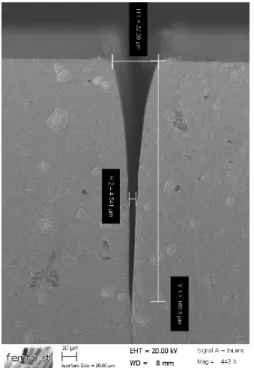
femto-second laser ablation as we can align the laser beam on the ring patterns. The ceramic is etched deeper than 100 µm, yielding the usual laser etching profile due to the light beam Gaussian distribution and light absorption when entering deeper in the bulk (see Figure 2).
Figure 1: Technological steps of the fabrication of a 6 channel annular array transducer combining femto-laser
micromachining and connection pad electroforming
Figure 2: Details of a femto-second laser beam etching profile in the ceramic etching profile in the ceramic – the top side kerf is near 30µm and decreases down to 10µm at
about 50µm deep
The grooved structure is then filled with a resist and a backing is spread on the connection surface (the electrically active one). Figure 3 (b) shows a general view of the contact pads before spreading the backing onto the structure. The piezoelectric ceramic is then lapped down to the expected thickness (near 50µm) depending on the
expected operating frequency. Th resulting front side is finally metalized with aluminum (electrically connected to the ground for shielding the active face). Initially, a matching layer is expected to be added to enlarge the final bandwidth of the transducer, but we did not achieve this step in the present work.
(a)
(b)
Figure 3: Close view of the transducer – (a) After thick photoresist patterning (b) After dots electroforming and
femto-second laser etching
Several probes have been fabricated and tested along this flowchart. Figure 4 shows an example of a probe totally connected and ready to be characterized.
Figure 4: Photo of the whole probe after backing filling and electrical connection for characterization tests (the back
Although this approach is not completely new, we show that rather thin kerfs have been achieved compatible with the beam-forming requirements, compatible with the fabrication of the whole probe.
3
Experimental and theoretical
characterization
The electrical response of each transducer's channel has been measured by means of an impedance analyzer. All the rings were found operational. A major contribution is observed near 45 MHz and a smaller one just beneath 50 MHz for all the rings. We can see these results on the Figure 5 (a). These characteristics have been also predicted using finite element analysis. A simple 2D axi-symmetric mesh has been performed, only accounting for the piezoelectric ceramic and the backing. The corresponding curves are plotted on Figure 5 (b), showing the rather good agreement between theory and experiments.
(a)
(b)
Figure 5 : Theory/experiment assessment (a) Impedance analyzer measurements of the channel admittance (b)
axi-symmetric finite element simulation of the annular transducer
We also intend to test and simulate the device operating in water. For the simulation work, we have to implement a boundary approach based on the Green's function of the radiation medium. Since in that situation, the Green's function correspond to a Bessel function [2], there is no particular difficulty to program that calculation.
4
Driving electronics
A dedicated electronics has been developed to control the probes. The basic principle of the electronics is reported in Figure 6.
Figure 6 : Principle diagram of the implemented electronics for driving the probe
The driving electronics is built around an AdUC7026 micro-controller which mainly sequences the whole system operation. It drives first a Direct Digital Synthesis (DDS AD9954) circuit to create a high frequency clock. An Erasable Programmable Logic Device (EPLD) is then cadenced using the clock to build the transducer driving signal, consisting in a simple period voltage alternation. Once this signal generated, it enters in the amplifier stage consisting in a MD1820 conditioner followed by a power transistor from SuperTEX yielding +/-40V signal dynamics. The whole stage exhibits a cutoff frequency near 100MHz, compatible with the targeted working frequency. A switch is used to isolate both emission and reception stages. The later mainly is composed of an impedance matching circuit and an amplifier stage to provide processable signals.
Figure 7 : Photo of the operational electronics card The size of the electronics is not optimized as we did not face any constraints at this development level.
In order to test this driving electronics card, several tests with commercial probes have been performed. The 6 channels were found operational. Figure 8 shows the results obtained with a commercial probe. We can observe the emission pulse and the received echo. The contributions we can see between the pulse emission and the echo are due to the impedance break of the switch. Finally, our probe has been tested in water and an echo has been observed as expected.
Figure 8: Echo observed using a commercial probe: electronics driving validation
5
Conclusion
A new process using deep UV lithography, Ni electroforming and femto-second laser ablation has been proposed for the fabrication of a 6 channel annular array operating at 50 MHz for ophtalmology applications. The devices have been successfully fabricated and tested. As expected, their operating frequency is near 50 MHz, and all the channels were found to operate as expected. We have also used an axi-symmetric finite element analysis to simulate the implemented devices. A comparison between the theoretical and experimental admittance measurements enables to check the fabrication process and is necessary to optimize the probe design. We also have developed a driving electronics capable to operate the whole probe, based on a combination of a micro-controller, a DDS and an EPLD for signal synthesis. The driving electronics card has been successfully tested with different commercial probes. Finally, we have tested our probe in water and an echo has been observed as expected.
Acknowledgments
This work has been supported by the Agence Nationale de la Recherche as the SAFIRO project under grant # ANR-06-RNTS00902 of the Réseau National des Technologies pour la Santé.
Références
[1] Snook A., Hu C.-H., Shrout T. R., Shung K. K., “High-Frequency Ultrasound Annular-Array Imaging. Part I: Array Design and Fabrication”,
IEEE transactions on ultrasonics, ferroelectrics, and frequency control, 53, no. 2, 300-308 (2006).
[2] Kino G.S., Acoustic Waves: Devices, Imaging, and Analog Signal Processing, Publisher: Prentice Hall, ISBN 9780130030474 (1987).
Pulse +/40V