To link to this article : DOI:10.1016/j.wear.2014.04.023
URL :
http://dx.doi.org/10.1016/j.wear.2014.04.023
This is an author-deposited version published in:
http://oatao.univ-toulouse.fr/
Eprints ID: 11715
To cite this version:
Delebarre, Corentin and Wagner, Vincent and Paris, Jean-Yves and Dessein,
Gilles and Denape, Jean and Gurt-Santanach, Julien An experimental study of the
high speed interaction between a labyrinth seal and an abradable coating in a
turbo-engine application. (2014) Wear, vol. 316 (n° 1-2). pp. 109-118. ISSN
0043-1648
O
pen
A
rchive
T
oulouse
A
rchive
O
uverte (
OATAO
)
OATAO is an open access repository that collects the work of Toulouse researchers
and makes it freely available over the web where possible.
Any correspondence concerning this service should be sent to the repository
administrator:
staff-oatao@listes.diff.inp-toulouse.fr
!
An experimental study of the high speed interaction between
a labyrinth seal and an abradable coating in a turbo-engine application
C. Delebarre
a,b,n, V. Wagner
b, J.Y. Paris
b, G. Dessein
b, J. Denape
b, J. Gurt-Santanach
aaTURBOMECA, Avenue Joseph Szydlowski, 64510 Bordes, France
bUniversité de Toulouse, Laboratoire Génie de Production, Ecole Nationale d'Ingénieurs de Tarbes, 47 Avenue d'Azereix, BP 1629, 65016 Tarbes Cedex, France
Keywords: Labyrinth seal Thermal spray coatings High speed interaction
a b s t r a c t
A new high-speed test rig was designed to simulate the interactions between labyrinth seals and abradable coatings in similar engine operating conditions. To determine a solution for turbo-engine efficiency enhancement, we investigated the clearance reduction between the rotary parts in air systems, the successive starts and stops, the thermal expansion and the vibrations that might cause direct rub interactions between a rotary seal, known as a labyrinth seal, and a turbo-engine housing coated with a sacrificial abradable material. High interaction speeds from 0 to 130 m s! 1were obtained
using a 5-axis milling machine fitted with a unique magnetic bearings spindle developed specifically for the study. The purpose of this paper is to study the interaction phenomena between an abradable material (Al–Si 6%) and a nickel alloy (Alloy 718) to obtain a first contact assessment under different turbo-engine operating conditions. The experimental results are first presented by visual observations of the posttest samples, as specified by accurate profile measurements. A quantitative approach to the interaction forces recorded during the tests and micrographic observations complete the preliminary study. This work provides new basic data for a preliminary study of the interaction between labyrinth seal teeth tips and abradable coatings in turbo-engine applications.
1. Introduction
For decades, a major concern of turbo machinery manufac-turers has been to increase engine efficiency by developing new materials capable of performing at higher temperatures and new technologies for fuel management and airflow direction. The technological level has been reached in the previous topics, and turbo-engine designers are seeking new solutions to increase turbo-engine efficiency and reduce polluting gas emissions. One method of improving engine efficiency is to control the airflow direction by reducing the clearance between the rotary parts in
the air systems [1,2]. In secondary air and sealing systems, the
control pressure differences and the levels of cooling between the engine modules are crucial to turbo-engine operation. These dynamic sealing systems are composed of a particular type of rotary seal, called the labyrinth seal. Labyrinth seals are used to reduce the loss of high-pressure gas within the engine cycle. This rotary seal controls the cooling air flow through the heated section of the engine and maintains the pressure balance on the rotor
shaft system. Rotary seals are located primarily on the rotating shafts between the compression stages and are composed of several teeth, which are integral parts of the motor shaft[3].
During operation, an engine is subjected to successive start and stop cycles, thermal expansion, vibration and mechanical loading[4]. Induced rotor–stator displacements might create undesirable interac-tions between the labyrinth teeth tips and the turbo-engine housing
[5]. In this case, the labyrinth teeth rub and form rub-grooves on the housing surface. To avoid undesirable wear from incursions of the labyrinth teeth onto bare metal, the insertion of an abradable material layer a few millimetres thick has been widely recognised as a robust solution. The turbo-engine housing is coated with a sacrificial abrad-able material that is thermally sprayed to preserve the structure in case of labyrinth/casing contact[6]. This coating could be composed of a metal phase and a self-lubricating non-metal phase that provide a high porosity rate and offer a good balance between abradability and erosion resistance[7]. This method is widespread in other extensively researched turbine-engine applications such as use in blade tips and
compressor housing[8–10]. The use of an abradable seal to prevent
rub interactions has encouraged aeronautical engineers to characterise the abradable behaviour during labyrinth seal interactions and to validate the design choices in various engine stages.
For that process, an understanding of the tribological behaviour between the labyrinth teeth and the abradable material is required. Today, research activities are mainly concentrated on n
Corresponding author at: Université de Toulouse, Laboratoire Génie de Production, Ecole Nationale d'Ingénieurs de Tarbes, 47 Avenue d'Azereix, BP 1629, 65016 Tarbes Cedex, France.
E-mail addresses:corentin.delebarre@enit.fr,
the labyrinth seal behaviour in its performance before and after interaction. Many experimental and numerical studies help to characterise the effect of the interactions on the aerodynamic seal performance and leakage levels generated by grooves left by the
labyrinth teeth[11–13]. Test rigs have been developed to quantify
the effects of interaction as well as the effects of tooth profiles and the geometry of labyrinth seal design on labyrinth seal
perfor-mance[14–16].
Very few studies focus on understanding the contact between
the labyrinth seal and the abradable coating. Dowson et al. [17]
and Whalen et al.[18]developed a full-scale facility based on a
grinding machine to study the behaviour of abradable materials (mica filled tetrafluoroethylene (TFE), silicone rubber, aluminium polyester and nickel graphite) in contact with a labyrinth seal at relative speeds up to 25 m s! 1and 130 m s! 1respectively. A linear
actuator controlled the feed-rate from 2.54 m s! 1
to 25.4 m s! 1
, which these authors defined as the labyrinth thermal expansions and vibrations caused by a passage of critical speed. They estab-lished a “good abradability” condition for the tested materials by defining a ratio corresponding to the depth of the groove divided by the material loss of the labyrinth. An additional condition
describing abradability was defined by Mutazim et al. [19] by
characterising the rub-groove geometry of seven abradable mate-rials (aluminium, Al–bronze, Al–Si–polyester, Al–bronze–polye-ster, Al–Si–polyimide, Cu–Sn–Bi, Cu–Sn–Pb) subjected to contact with a labyrinth seal. A specific full-scale test rig was performed
under unlubricated conditions with a coating casing of 16.5 cm in diameter segmented into three pieces and a labyrinth seal com-posed of four knife edge rows fabricated from 4340 steel.
Two companies, Sulzer Innotec and Sulzer Metco[20], worked
closely on the development of abradable materials using a specific test rig adapted to the application of labyrinth/abradable interac-tions. It consists of an alloy disc that accommodates four contin-uous seal trips on the outer circumference, a movable specimen coated with an abradable material and a heating device. The wear behaviour is evaluated by measuring and recording the seal strip cutting-edge velocity, the temperature of the shroud segment, the wear track depth and the incursion depth. The seal strip height variation is recorded as the shroud surface temperature and by the test video. The abradable coating specimen is mounted on a precision table actuated by two stepper motors with a step length
of 0:15
μ
m. A programmable controller controls the specimen,allowing control of the depth, the return velocity and the sample incursion immediately after reaching the desired depth. A propane burner heats the abradable surfaces for testing at temperatures from 25 to 700 1C.
An improved understanding of the phenomena of labyrinth seal wear with abradable materials and the development of improved abradable materials for use in turbo-engines is needed. This paper describes the results of an investigation to undertake a first assessment of high-speed mechanical interactions between an Alloy 718 labyrinth seal and an abradable Al–Si 6% coating. An original test rig was specifically designed to simulate these interactions in realistic operating conditions.
2. Experimental methodology 2.1. Test rig design
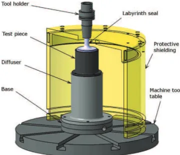
To simulate and study the wear interactions between labyrinth seals and abradable coatings in operating conditions similar to those of a turbo-engine, a 5-axis UCP600 VARIO milling machine from Mikron was used with a specific experimental device as a test rig (Fig. 1). The 5-axis milling machine tool has the specificity to be fitted with a unique magnetic bearings spindle which allows a maximum rotation speed of 40 000 rpm and maintains the spindle vertically without mechanical contact. This maximum rotation speed is representative of the maximum speed reached by a free turbine during turbo-engine operation. The test rig is primarily
composed (Fig. 1) of a labyrinth seal representative of an actual
motor shaft section part that is shrinking on a HSK-50 tool holder instead of a cutting tool (Fig. 2(a)). The interaction is performed inside a special tube sample coated in the inner periphery with abradable materials. This sample is representative of the turbo-engine housing facing the labyrinth seals in the secondary airflow
Fig. 1. The experimental device used to simulate the interactions between the labyrinth seal and the abradable coatings.
section of a turbo-engine (Fig. 2(b)). A special tube covered with the abradable material was precisely settled and fixed on the machine tool table using a diffuser and a base piece. This diffuser is specifically designed to receive and ensure precise positioning of the tube sample to avoid default concentricity that would be disruptive to the nature of the contact. Its design allows simulation of the sealing of the labyrinth seal during operation by pressuris-ing the entire system. For future tests, it would allow measurpressuris-ing of the leakage level and sealing performance of a labyrinth seal after interaction. A protective shield was designed to withstand and absorb any sample rupture during the tests. It consists of a stainless steel tube with a 340 mm inner diameter and a 15 mm thick cover.
The interactions between the labyrinth teeth tips and the abradable coatings were controlled using the high speed milling machine capabilities, thus respecting the contact nature of turbo-engines (including the continuous contact, rotation speed, radial incursion speed and interaction time). The rotation speed of the
labyrinth seal varies from 0 to 40 000 rpm, corresponding to a
tangential contact speed varying from 0 to 130 m s! 1with current
labyrinth seal geometry. The geometric tolerances of the samples and their assemblies require precise control of the mechanical
clearance of 150
μ
m between labyrinth teeth tips and theabrad-able coating. The dynamic properties of the machine tool tabrad-able actuator (the maximal acceleration value) achieve a radial
incur-sion speed range of 0.001–25 mm s! 1
fixed by an incursion depth and mechanical clearance based on real engine conditions.
2.2. Test materials
The test series was performed using labyrinth seal specimens made of Alloy 718; the chemical composition is presented in
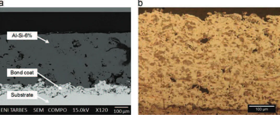
Table 1. These labyrinth seals are designed with three successive circular teeth that are 65.8 mm in external diameter. The labyrinth seal rotation speed reached during the tests requires precise sample machining characterised by very specific geometric toler-ances. The machining accuracy minimises the concentricity error of the teeth and achieves good labyrinth seal balancing at high rotation speeds. The Al–Si 6% abradable coating was sprayed inside the stainless steel housing support, using a thermal wire flame spray process. The spray was applied onto a bond coat at
approximately 20–150
μ
m thick. The extensive roughness of thebond coat promotes good cohesion of the deposit (Fig. 3). The
Al–Si 6% coating was particularly heterogeneous and porous because of the abradable composition and the spraying method. The multiple layer spraying method and the spraying distance led to porosity in the coating. Once coated, the housing support was machined by milling to control the abradable thickness (approxi-mately 1 mm) and the internal diameter, which defined the mechanical clearance between the abradable coating and the labyrinth seal teeth. The test piece features an abradable useful track of 2 cm.
Table 1
Chemical composition and material properties of Alloy 718. Elements (% by mass)
Ni Cr Fe Mo Nb Co Mn
Min 50 15 2.8 4.75
Max 55 21 Balance 3.3 5.50 1.0 0.35
Material properties
Tensile strength (MPa) 1310
Yield strength (MPa) 1110
Elastic modulus (GPa) 206
Hardness (HV150) 370
Density (g cm! 3) 8.19
Melting point (1C) 1300
Thermal conductivity (W m! 1K! 1) 11.2
Fig. 3. (a) The microstructure in a sectional view of the Al–Si 6% coating on the stainless steel substrate and (b) observation of the Al–Si 6% coating microstructure after a
Keller attack under on optical micrograph[21].
Table 2 Test parameters. Test no. Rotational speed (Vr) (rpm)
Labyrinth tip speed (Vt)
(m s! 1)
Incursion speed (Vinc)
(mm s! 1) Incursion depth (Dp) (mm) Interaction time (s) 1 37 500 130 0.005 0.2 40 2 37 500 130 25 0.2 0.008 3 12 500 43 0.005 0.2 40 4 12 500 43 25 0.2 0.008 5 5000 17 0.005 0.2 40 6 5000 17 25 0.2 0.008
2.3. Test parameters
The main test parameters used to simulate the interactions between labyrinth seals and abradable coatings were labyrinth tip speed, rotation speed, incursion speed and incursion depth. A test matrix was selected to cover various conditions encountered in turbo-engines such as engine vibration, excessive mechanical
loading or thermal expansion; the test matrix is shown inTable 2.
Three labyrinth seal rotation speeds were selected and defined as representative interaction velocities during turbo-engine opera-tion. Two radial incursion speeds were fixed, thus defining two types of interaction (a high and a low incursion speed). The overall incursion depth was kept constant and was defined following a wear investigation of the worn abradable material in a turbo-engine.
A precise experimental protocol was developed to simulate the controlled interactions. The procedure consisted of precisely positioning the labyrinth seal sample inside the abradable test piece using a Renishaw touch-probe to precisely determine the geometric centre of the abradable test piece. Once positioned inside the tube, the labyrinth seal was brought to the desired speed. Once this speed was reached, the contact was performed by a radial translation, toward the rotating labyrinth seal, of the abradable test piece fixed on the machining tool table. The incursion speed was fixed by the test parameters, and the total
radial incursion length was fixed to 350
μ
m (the sum of themechanical clearance and the desired abradable incursion depth).
Once the translation reached a length of 350
μ
m, the abradabletest piece was quickly translated in the opposite direction of the initial position. the abradable test piece was removed for further analysis.
2.4. Contact geometry
The interaction between the labyrinth tip tooth and the abradable coating is characterised by a complex contact geometry induced by the incursion of a trapezoidal section of a circular tooth in a tube coated with the abradable material. This contact geometry ideally evolves continuously during the test, according
to the radial incursion evolution (see Fig. 4). The machining
precision of the labyrinth seal teeth (the geometric tolerances and unbalance) and the positioning precision of the test pieces and the spindle stiffness (hypothesised to be infinite during contact) have an important effect on the nature of the interaction. The use of three different teeth labyrinth seals leads to three different contact behaviours, which are specific for each tooth with the identical test conditions. During the interaction, the geometric confinement of the central tooth most likely leads to a thermal phenomenon.
2.5. Contact forces measurement
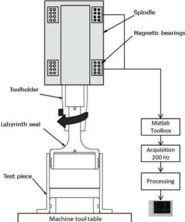
Special instrumentation was developed to record the forces resulting from the characteristics of the magnetic bearings spindle
fitted to the test rig. Balance and perfect alignment of the rotating assembly were obtained by the continuously controlled current of the spindle electromagnets. This specificity was performed to maintain the centre rotation shaft axis responsiveness to any change of load from an external force or a disturbance from a solid rotor imbalance. In the labyrinth teeth incursions into the abradable coating, the interaction forces were directly transmitted
onto the magnetic bearings (torque induced during contact)[22].
These interaction forces were then compensated for by the control current signals of the magnetic bearings.
The main benefit of the magnetic bearings spindle fitted on the test rig is in the capability of recording their control current signals. Two radial magnetic bearings fit the machine tool spindle and are managed using a special Matlab toolbox developed by spindle manufacturers for monitoring the functioning parameters. These signals are recorded during interactions at a sampling frequency of 200 Hz and processed as values of the contact forces (Fig. 5). The force measurements are represented using two representations. The first representation is based on the calcula-tion of the normal and tangential components of the overall forces applied on the labyrinth. The second is based on the norm
Fig. 4. Sectional view of the evolution of the contact geometry during interaction.
calculation defined in the following equation: J F!J ¼ ffiffiffiffiffiffiffiffiffiffiffiffiffiffiffiffiffiffiffiffiffiffiffiffiffiffiffiffiffiffiffiffiffiffiffiffiffiffiffiffi ðFxÞ2þ ðFyÞ2þ ðFzÞ2 q : ð1Þ
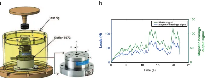
The processing is the result of a preliminary study designed to calibrate the recorded signals. This calibration was conducted by comparison of the signals between a Kistler type 9272 dynam-ometer specifically settled on the test rig device and the recorded
magnetic bearings signals (Fig. 6(a)). Different tests were
con-ducted with different incursion speeds and showed the existence of a single proportionality coefficient to be applied on the magnetic bearing signals to obtain the force of the interactions (Fig. 6(b)).
3. Results and discussion 3.1. Analysis of the test samples
A first post mortem analysis of rub interactions was performed by visual observation of the contact protagonists after the tests. The rub-grooves left by the labyrinth seal teeth on the Al–Si 6% coating and the
changes of the labyrinth seal teeth geometry were observed.Fig. 7
presents the rub-grooves on the Al–Si 6% coating from the interactions of all the test parameters. Different rub-groove morphologies were observed according to the different test parameters. Some rub-grooves present a significant amount of plastically deformed material on both sides of the groove. This deformation is observed for the high-incursion speed tests (test nos. 2, 4, 6) and for test no. 1 (a
low-incursion speed and labyrinth tip speed of 130 m s! 1). The
rub-grooves from test nos. 3 and 5 (at a low-incursion speed and low rotational speed) appear with a morphology that could be qualified as “clear cut”, without any positive amount of deformed material on both sides of the groove. Noticeable changes or severe wear of the labyrinth seal teeth were observed after the tests, except after test nos. 3 and 4. Material transfer was observed on the top of the labyrinth seal teeth and was identified as transfer of the Al–Si 6% coating, as shown inFig. 8.
These first observations suggest that rub-grooves morphologies
are most likely affected by the incursion speed Vinc parameter.
Considering the result from test no. 1, the Vrlabyrinth rotation
speed appears to be a significant additional parameter. To confirm the rub-grooves visual observations, accurate profile measure-ments were conducted with a SOMICRONIC 2C profilometer at
the maximum incursion depth area (Fig. 9). The positive heights
and negative depths were identified and quantified by the Z 1 and
0 5 10 15 20 25 0 50 100 Loads (N) Time (s) 0 5 10 15 20 250 50 100 150 Magnetic bearings output signal Kistler signal Magnetic bearings signal
Fig. 6. (a) The experimental device used to calibrate the force measurement using magnetic bearings and (b) the correlation between the Kistler signal and the magnetic bearings signal.
Z 2 values, respectively. In most cases, the rub-grooves formed on
Al–Si 6% were deeper than the 200
μ
m fixed by the maximumradial incursion of the labyrinth seal. The three rub-grooves formed by the three teeth of a single labyrinth seal had different incursion depths. This finding is consistent with the hypothesis of the existence of different contact behaviours for each tooth on a single labyrinth seal. For each test, the deeper rub-groove corre-sponded to the tooth confined between the other two. This finding could be explained by an additional wear phenomenon within the
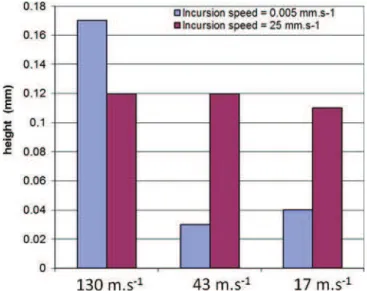
affected area because of the thermal confinement.Fig. 10presents
a diagram of the maximum heights of the deformed coating versus the rotation and the incursion speed. At the low-incursion speed (Vinc¼ 0:005 mm s
! 1), the labyrinth tip speed has a significant
effect on the heights of the deformed coating. For test nos. 3 and 5
(Vt¼ 43 m s! 1 and Vt¼ 17 m s! 1), the height of the deformed
coating was lower, whereas the rub-groove depths were nearly identical. This examination shows a material deformation wear mechanism at high rotation speed, in contrast to the material removal wear mechanism at a lower rotation speed. This wear mechanism difference might be explained by the different tem-perature dissipation levels generated by the interaction with the Al–Si 6% coating. This temperature dissipation level was affected by the labyrinth seal rotation speed, which affected the ductile behaviour of the coating. We analysed the interaction force measurements, particularly the associated frictional forces, during contact.
3.2. Analysis of interaction forces
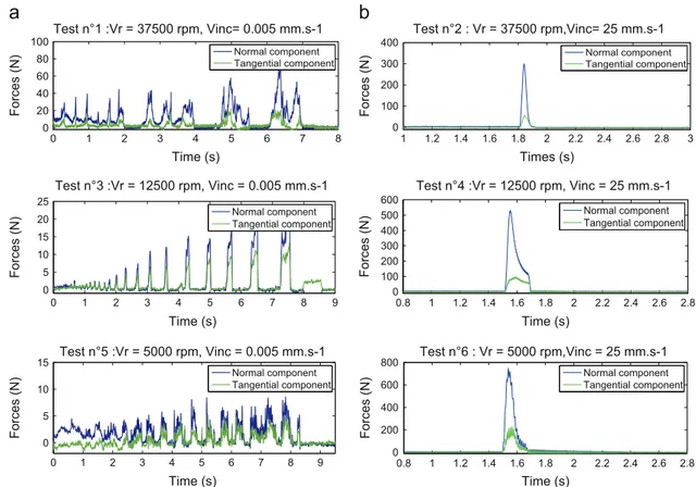
First, the two incursion speeds (Vinc¼ 0:005 mm s
! 1 and
Vinc¼ 25 mm s! 1) allow observations of two different sets of
signals that are directly associated with different interaction times.
Fig. 11(a) shows the typical signals recorded for the tests at low-incursion speeds. These signals (the tangential component and normal component) are characterised by cyclic variations com-posed of non-contact periods in which the interaction forces are close to zero. In addition to the noncontinuous contact evolution from the labyrinth seal machining precision, these phenomena might be associated with a sudden Al–Si 6% pick-up followed by adjustment of the mechanical clearance thus created. The increase in the maximum force value at each cycle noticed in the signals could be partially explained by the increase of the contact surfaces caused by the incursion of the trapezoidal tooth section.Fig. 11(b) shows the typical signals recorded for the high incursion speed tests. This signal is composed of a very fast maximum rise time
( ' 0:005 ms), which corresponds to the cessation of the labyrinth
seal incursion and of a drop in the force.
Second, the use of the interaction force norm, as stated in
Section 2.5, provides a global vision of the forces involved during the interactions. It is used in a force quantitative approach and provides a comparison criterion for the maximum forces induced
by contact. Fig. 12presents the maximum force values from the
Fig. 8. Al–Si 6% transfer on the labyrinth seal teeth after test no. 3 (Vr¼
12 500 rpm, Vinc¼ 0:005 m s
! 1).
Fig. 9. the measurement depths of the grooves, corresponding to the six test conditions, using a SOMICRONIC 2C.
Fig. 10. The maximum heights of deformed coating according to the rotational and incursion speeds.
norm signals versus the rotation and incursion speed conditions. The maximum forces generated by the high-incursion speed tests are significantly higher than those at the low incursion speeds. At the low incursion speeds, the maximum forces are in a range of 8–75 N compared to a range of 300–780 N for the high incursion speeds. In agreement with previous observations, rub-grooves characterised by a low amount of deformed coating are obtained with interaction forces lower than 75 N.
Another trend is observed inFig. 12in the comparison of the
maximum force evolution for different incursion speeds. At low incursion speeds, the increase of the rotation speed induces a gradual increase of the maximum interaction forces. Conversely for the high incursion speeds, when the rotation speed decreases, the interaction forces increase.
3.3. Micrographic rub-groove examinations
Micrographic examinations of the rub-grooves were performed
on the Al–Si 6% abradable surface after the tests.Fig. 13presents
a sectional view of three rub-grooves from test no. 1 (Vp¼
37 500 rpm, Vinc¼ 0:005 mm s
! 1, D ¼0.2 mm). This sectional view
corresponds to the location where the incursion depth of the labyrinth teeth is the greatest. This SEM image shows the precise rub-groove geometry formed in Al–Si 6% and underlines the rub-groove widths that are slightly greater than the theoretical tooth dimensions. The measured rub-groove depths are consistent with the measurements performed with the profilometer. Con-sidering the coiled shape of the deformed coating outside the rub-groove, the SEM image demonstrates the existence of a material expulsion mechanism by the plastic deformation on both sides of the rub-groove (Fig. 13). A slight Al–Si 6% densification is identified around the rub-groove. The SEM images in the sectional view highlight lighter areas around two rub-grooves that appear to be characterised by a chemical constitution different from that of the
Al–Si 6% coating (Fig. 13). The SEM images in the backscattered
electron mode of the first and the third rub-grooves from test no. 1 reveal the existence of a different phase around the rub-groove (Fig. 14(a) and (b)). This lighter area is not noticeable on the middle rub-groove from test no. 1.
A rub-groove EDX analysis of the Al–Si 6% coating identified the presence of nickel and chrome, which are the basic elements of
Alloy 718, which emanated from the labyrinth seal teeth (Figs.15
and16). The transfer of Alloy 718 is perceptible on two of the three rub-grooves from the identical labyrinth seal. It is likely that the differences in the rub-groove depths and the matter transfer are correlated. This matter transfer from the labyrinth seal to the
0 1 2 3 4 5 6 7 8 0 20 40 60 80 100 Time (s) Forces (N) Normal component Tangential component 0 1 2 3 4 5 6 7 8 9 0 5 10 15 20 25 Time (s) Forces (N) Normal component Tangential component 0 1 2 3 4 5 6 7 8 9 0 5 10 15 Time (s) Forces (N) Normal component Tangential component Test n°1 :Vr = 37500 rpm, Vinc= 0.005 mm.s-1 Test n°3 :Vr = 12500 rpm, Vinc = 0.005 mm.s-1 Test n°5 :Vr = 5000 rpm, Vinc = 0.005 mm.s-1 0.8 1 1.2 1.4 1.6 1.8 2 2.2 2.4 2.6 2.8 0 100 200 300 400 500 600 Time (s) Forces (N) Normal component Tangential component 1 1.2 1.4 1.6 1.8 2 2.2 2.4 2.6 2.8 3 0 100 200 300 400 Times (s) Forces (N) Normal component Tangential component 0.8 1 1.2 1.4 1.6 1.8 2 2.2 2.4 2.6 2.8 0 200 400 600 800 Time (s) Forces (N) Normal component Tangential component Test n°2 : Vr = 37500 rpm,Vinc= 25 mm.s-1 Test n°4 :Vr = 12500 rpm, Vinc = 25 mm.s-1 Test n°6 : Vr = 5000 rpm,Vinc = 25 mm.s-1
Fig. 11. (a) Typical interaction force signals recorded for the low incursion speed tests ðVinc¼ 0:005 mm s
! 1Þ and (b) typical interaction force signals recorded for the high
incursion speed tests ðVinc¼ 25 mm s! 1Þ.
Fig. 12. Maximal interacting forces versus the rotational speed ðVrÞ and the
abradable coating is characterised by an accumulation of layers mixed with the Al–Si 6% coating in the bottom of the rub-groove (Fig. 17(b)). The Alloy 718 transfer was also observed in the front view of the bottom of the rub-groove on the entire surface of
the observed sample (Fig. 18(a)). Magnification of the rub-groove
bottom surface confirmed the Alloy 718 smear by the observation of a striated surface (Fig. 18(b)). Significant surface cracking indi-cates a significant rise in temperature followed by rapid cooling (Fig. 18(b)).
4. Conclusions
To enhance turbo-engine efficiency by reducing the mechanical clearance between rotary parts, an understanding of the contact between labyrinth seals and abradable coatings and improvement of the methodologies for dimensioning dynamic sealing systems are necessary. This requirement should be studied to characterise
the material coupling (in which one material undergoes change, while the other imposes change) by simulating the interactions in turbo-engine operational conditions. Interactions between an Al–Si 6% abradable coating and an Alloy 718 labyrinth seal were performed using a high-speed test rig specifically developed to
achieve a maximum interaction speed of 130 m s! 1
.
A first assessment of the high-speed interactions was con-ducted by an analysis of test samples. Visual rub-groove observa-tions, accurate profile measurements, maximum interaction force analysis and micrographic examinations revealed different mate-rial deformation and wear phenomena and significant interaction parameters as follows:
(
Observation of damage from a deformation phenomenon onthe Al–Si 6% coating at high incursion speed and high rotation speed.
(
Observation of a material removal wear phenomenon at lowincursion speed and low rotation speed. The observation was
Fig. 13. SEM image in sectional view of the three rub-grooves from test no. 1 (Vp¼ 37 500 rpm, Vinc¼ 0:005 mm s
! 1, D ¼0.2 mm).
Fig. 14. (a) SEM image in backscattered electron mode of the first rub-groove from test no. 1 and (b) SEM image in backscattered electron mode of the third rub-groove from test no. 1.
based on the transfer, characterised by an accumulation of layers in the rub-groove, from the labyrinth seal teeth onto the Al–Si 6% coating.
(
Influence of the labyrinth rotation speed on the rub-groovemorphology and interaction forces.
This study should be complemented by evaluating the abrad-able behaviour of the labyrinth seal radial incursion. A test study
should be performed by fixing the test parameters to perform successive incursions.
Acknowledgments
These investigations were supported by the European Commis-sion through the FP7 E-BREAK project under Grant agreement no.
Fig. 16. Identification of chemical elements by the EDX analysis around the third rub-groove in test no. 1.
Fig. 17. (a) SEM image in backscattered electron mode of the first rub-groove in test no. 1 and (b) SEM image of the accumulated layers of Alloy 718.
Fig. 18. (a) SEM image in front view of the Al–Si 6% surface from test no. 1 (Vp¼ 37 500 rpm, Vinc¼ 0:005 mm s
! 1, D ¼0.2 mm) and (b) SEM image of the rub-groove bottom
surface from test no. 1 subjected to smearing (Vp¼ 37 500 rpm, Vinc¼ 0:005 mm s
314366 and by SAFRAN-TURBOMECA. The study also received financial support of the Agence Nationale de la Recherche et de la Technologie (ANRT). The support of these organisation is grate-fully acknowledged.
References
[1] W. Dalzell, Abradable Seals Having Improved Properties, 2002.
[2]M. Dorfman, U. Erning, J. Mallon, Gas turbines use abradable coatings for clearance-control seals, Seal. Technol. 97 (1) (2002) 7–8.
[3]P. Dowson, M. Walker, A. Watson, Development of abradable and rub-tolerant seal materials for application in centrifugal compressors and steam turbines, Seal. Technol. 12) (2004) 5–10.
[4]G. Jacquet-Richardet, M. Torkhani, P. Cartraud, F. Thouverez, T.N. Baranger, M. Herran, C. Gibert, S. Baguet, P. Almeida, L. Peletan, Rotor to stator contacts in turbomachines. Review and application, Mech. Syst. Signal Process. 40 (2) (2013) 401–420.
[5] R. Schmid, F. Ghasripoor, M. Dorfman, X. Wie, An overview of compressor abradable thermal sprays, in: Surface Engineering International Thermal Spray Conference ITSC, 2000, p. 406.
[6]R. Rajendran, Gas turbine coatings: an overview, Eng. Fail. Anal. 26 (2012) 355–369.
[7]Y. Maozhong, H. Baiyun, H. Jiawen, Erosion wear behaviour and model of abradable seal coating, Wear 252 (2002) 9–15.
[8]C. Padova, Casing treatment and blade-tip configuration effects on controlled gas turbine blade tip/shroud rubs at engine conditions, J. Turbomach. 133 (2011) 011016-1–011016-12.
[9] S. Baïz, Experimental study of blade/abradable contact: contribution to the mechanical characterization of abradable materials and their dynamic inter-action on rotating test bench with a rotating test rig with a blade (Ph.D. thesis), Ecole centrale de Lille, 2011.
[10] M. Cuny, Contribution to the local characterization of pairs of materials involved during rotor/stator contact in a turbomachine (Ph.D. thesis), Université de Lorraine, 2012.
[11] M. Proctor, J. Delgado, Leakage and Power Loss Test Results for Competing Turbine Engine Seals, Technical Report, NASA/TM, 2004.
[12] I. Delgado, M. Proctor, Continued Investigation of Leakage and Power Loss Test Results for Competing Turbine Engine Seals, Technical Report, NASA/TM-2006-214420, 2006.
[13]D. Collins, J. Teixeira, P. Crudgington, The degradation of abradable honeycomb labyrinth seal performance due to wear, Seal. Technol. (2008) 7–10. [14]S. Wittig, U.S.K. Jacobsen, S. Kim, Heat transfer in stepped labyrinth seals,
ASME J. Eng. Gas Turbines Power 110 (1988) 63–69.
[15] L. Dobek, Labyrinth Seal Testing for Lift Fan Engines, Technical Report, Pratt & Whitney Aircraft Division United Aircraft Corporation, 1973.
[16]A. Gamal, J. Vance, Labyrinth seal leakage test: tooth profile, tooth thickness, and eccentricity effects, ASME J. Eng. Gas Turbines Power 130 (2008) 012510. [17] P. Dowson, S. Ross, C. Schuster, The investigation of suitability of abradable seal materials for application in centrifugal compressors and steam turbines, in: Proceedings of the Twentieth Turbomachinery Symposium, 1991.
[18] J. Whalen, E. Alvarez, L. Palliser, Thermoplastic labyrinth seals for centrifugal compressors, in: Proceedings of the Thirty-Third Turbo Symposium, 2004. [19]Z. Mutasim, L. Hsu, E. Wong, Evaluation of plasma sprayed abradable coatings,
Surf. Coat. Technol. 54–55 (1992) 39–44.
[20] S. Wilson, Ensuring Tight Seals, Vol. 2, Technical Report, Sulzer Technical Review, 2007.
[21] A. Prillieux, L. Talotte, Determining the evolution of the mechanical properties of AlSi and abradable AlMn aluminum base, Technical Report, Institut Carnot Cirimat, 2013.
[22] S. Auchet, P. Chevrier, M. Lacour, P. Lipinski, A new method of cutting force measurement based on command voltages of active electro-magnetic bear-ings, Int. J. Mach. Tools Manuf. 44 (14) (2004) 1441–1449.