REPUBLIQUE ALGERIENNE DEMOCRATIQUE ET POPULAIRE
يملعلا و ثحبلا يلاعلا ميلعتلا ةرازو
MINISTERE DE L’ENSEIGNEMENT SUPERIEUR ET DE LA RECHERCHE
SCIENTIFIQUE
-
1
- فيطس سابع تاحرف ةعماج
UNIVERSITE FERHAT ABBAS SETIF-1-
THESE
Présenté à la Faculté de Technologie
Pour l’Obtention du Diplôme de
DOCTORAT
Domaine : Sciences et Technologie
Filière : Electrotechnique
Option : Commande Electrique
Par
M
r: Fayssal AMRANE.
Contribution à la Commande d’un Système
de Conversion Eolien à base de la
Génératrice Double Alimentée
Soutenu le: 13/05/2018 devant un Jury composé de:
Pr. RADJEAI Hammoud.
Professeur. Université de Sétif-1.
Président.
Dr. CHAIBA Azeddine.
MCA.
Université de Khenchela. Directeur de Thèse.
Pr. AOUZELLAG Djamal.
Professeur. Université de Bejaia.
Examinateur.
Dr. BENAICHA Samira.
MCA.
Université de Sétif-1.
Examinateur.
PEOPLE'S DEMOCRATIC REPUBLIC OF ALGERIA
يملعلا و ثحبلا يلاعلا ميلعتلا ةرازو
MINISTRY OF HIGHER EDUCATION AND SCIENTIFIC RESEARCH
-1 - فيطس سابع تاحرف ةعماج
UNIVERSITY FERHAT ABBAS SETIF -1-
THESIS
Submitted at Faculty of Technology
This thesis is submitted in fulfillment of the requirement for the degree
PhD
Field: Sciences and Technology
Specialty: Electrical Engineering
Option: Electrical Control
By
M
r.Fayssal AMRANE
Contribution to the Control of Wind Energy
Conversion System based on Doubly Fed
Induction Generator
University Ferhat ABBAS of Setif-1 (UFAS-1), ALGERIA
Page -i-
Dedication
I dedicate this thesis to my
Mother and my Father
To my wife for her patience and encouragement
To my Brother and my Sister
I dedicate this thesis to the memory of my
cousin: KERAGHUEL Yacine (Allah yarahmou)
I dedicate this thesis to the memory of my
best friend MEDJBER Walid (Allah yarahmou)…
To my colleagues and friends in my social and academic life.
30 December 2017.
Mr. AMRANE Fayssal.
Page -ii-
Above all, I would like to thank The Almighty God (ALLAH le tous puissant) for the wisdom and perseverance that he has been bestowed upon me during this research work, and indeed, throughout my life.
It has been a pleasure for me to work on this thesis. I hope the reader will find it not only interesting and useful, but also comfortable to read.
First and foremost, I would like to express my sense of gratitude and indebtedness to my supervisor Mr. CHAIBA Azeddine, Associate Professor at Department of Industrial Engineering University of Khenchela, Algeria, for his inspiring guidance, encouragement, and untiring effort throughout the course of this work. His timely help and painstaking efforts made it possible to present the work contained in this thesis. I consider myself fortunate to have worked under his guidance during 03 years (December 2014- December 2017).
Also, I express my heartfelt thanks to Mr. FRANCOIS Bruno, Full professor at Ecole Centrale de Lille for giving me a great opportunity to do a training long period (under the Franco-Algerian scholarship program PROFAS b+: Oct 2016- June. 2017) at Ecole Centrale de Lille, France in L2EP Laboratory (Laboratoire de d’Electrotechnique et d’Electronique de Puissance), for his time and for his valuable advices and comments.
I also wish to thank President of jury Mr. RADJEAI Hammoud Full Professor at the university of Setif-1 and member of the Automatic Laboratory of Setif LAS, and the members of the jury: Mr.
AOUZELLAG Djamal, Full Professor at the University of Bejaia, Mrs. BENAICHA Samira Associate
Professor at University of Setif-1, and member of the Automatic Laboratory of Setif LAS and Mr.
BOUAFIA Abdelouahab Associate Professor at University of Setif-1 and member of the Power
Quality in Electric Networks Laboratory, for serving as my committee members and taking the time to revise my thesis. I am thankful that in the midst of all their activities, they accepted to be members of the reading committee.
Last but not the least, I am grateful to my parents for their prayers, guidance and support throughout my education. Their inspiration and encouragement has been invaluable.
Page -iii-
لكشت هذه ةحورطلأا ةمهاسم يف ةسارد ةرطيسلا ىلع ماظن جاتنإ ةقاط حايرلا . وهو عوضوم ةنراقم وينقت ةيداصتقا نيب لكايهلا ةفلتخملا دلومل حايرلا ريغلا نمازتملا ذ و ةيذغتلا ةجودزملا ( DFIG ) سركملا مظنل ليوحت ةقاط حايرلا . ارظنو ةعيبطلل ةبلقتملا ،حايرلل رملأا يذلا ببسي رركتملا ريغتلا ددرتلل دنع م جرخ ،دلوملا نمف يرورضلا طبر ريخلأا عم لمحلا وأ ةكبشلا نم للاخ تلاوحم ةتباث نم لجأ نيسحت ةيعون ةقاطلا يف دهجلا ددرتلاو مادختساب تاينقت مكحتلا ةبسانملا . يف اذه قايسلا مت حارتقا ديدعلا نم تادحو مكحتلا ريغلا ةيطخلا ةنسحملا ( I/OLDC, IDPC و FOC ) مادختساب تلاوحم AC-DC-AC ( نع قيرط PWM وأ SVM ) ةرطيسلل ىلع راودلا نيسحتلو ءادأ ماظن حايرلا . ادانتسا ىلإ DFIG اميف قلعتي ريغتلاب ئجافملا ةعرسل حايرلا نارتقاو تاريغتم ةلاحلا ىلع لوط نيروحملا d) و (q جارختسلا ةردقلا ىوصقلا . مت عضو ةيجيتارتسا MPPT يف لمعلا نم لجأ ظافحلا ىلع ةمودعم هبش هيدر ةقاط ( لماعم ةردقلا ةدحولا يواسي 1 .) مت ذيفنت نينثا نم بصانم رابتخلاا ةيبيرجتلا ( نع قيرط dSPACE1103 و dSPACE1104 ىلع يلاوتلا مادختساب نينثا نم تاكاحملا ةينيبروتلا ةفلتخملا ) نامضل ءادلأا يلاعلا تادحول مكحتلا ةحرتقملا تحت تارابتخا ةناتم عبتتل عجرم تارايت راودلا ( Ird* و Irq* ) ةعرسلاو ( يف لك نم طئاسو : وبياه طرفو نمازتم .) مت حارتقا تادحو مكحت ةيوق ةيكذو ( لثم : PID , IP , MRAC , T1-FLC , T2-FLC , NFC و HCC ) ةرطيسلل ىلع ةقاطلا ةطشنلا ةيدرلاو ( Ps* و Qs* ) روص تايمزراوخلا ريغ ةيطخلا ( ةروكذملا اقباس ) نم DFIG يف تقولا يقيقحلا عم / نودب ةيجيتارتسا MPPT . مت ةسارد نيعضو لاصتلال يف ةاكاحملا بيرجتلاو ( ةطساو عم نحش لوزعم عضوو ةطبارتم عم ةكبشلا ) يف تقولا يقيقحلا نم لجأ ققحتلا نم ةحص هذه تايمزراوخلا . دقو مت طبر ةساردلا ةنراقملا ةيبيرجتلا نيب ةثلاث عاونأ نم تاحشرملا LC, L و LCL لكل تحت راودلا يلاحلا فلاتخلاا ( Ird* و Irq* ) ، نيب راودلا سكاعلاو ( SEMIKUBE ) ةيفصتل تايقفاوتلا نم ةيتلوفلا ةنكاسلا ،راودلاو اهلعجو يف لكش ةيبيج نامضل عجارم ةديج ةرطيسلل ىلع ةطلسلا . تارابتخلاا ةيبيرجتلا دكؤت ةناتم ءادأو طباوضلا ةحرتقملا يتلا مت جلاع ديدعلا نم لكاشملا نم ماظن حايرلا نم ؛ثيح لصفو تاريغتم ةلودلا نم لاك نيروحملا d) و (q ةيساسحلاو ريغتلل ،يرتمارابلا عبتتو ،عجارملا أطخو ،ةردقلا تقوو ةباجتسلاا زواجتلاو . :ةيحاتفمتاملك ةمظنأ ليوحت دلوم ،حايرلا ةقاط ريغلا نمازتملا وذ ةيذغتلا ، ةجودزملا ةطقن عبتت ةردقلا ،ىوصقلا جلاعم تاراشلإا .ةيمقرلاAbstract:
This thesis constitutes contribution to the study of the control of a wind energy production system. It is the subject of a technical-economic comparison of the different structures of the wind-turbine based doubly fed induction generator (DFIG), dedicated to wind energy conversion systems (WECS’s). Due to the fluctuating nature of the wind speed, which causes frequent frequency variation at the output of the generator, it is necessary to link this latter with the load or the grid by static converters in order to improve the voltage energy quality and in frequency using appropriate control techniques. In this context several improved nonlinear controls (IDPC, I/OLDC and FOC) have been proposed using AC-DC-AC converters (via PWM or SVM) to control the DFIG’s rotor in order to improve the performance of the DFIG wind system compared to the sudden variation of the wind speed and the coupling of the state variables along the two axes (d and q). To extract the maximum power; the MPPT strategy is achieved to keep the reactive power maintains to zero level (Power factor near to 1). Two experimental test benches were implemented (via dSPACE1103 and dSPACE1104 respectively using two different wind turbine emulators) in order to ensure the
high performance of the proposed controls under robustness tests of rotor current reference tracking (Ird* and Irq*) and speed
(under the two modes: Sub- and Super-synchronous). Robust and intelligent controllers (such as: PID, IP MRAC, T1-FLC, T2-FLC, NFC and HCC) have been proposed to control the images of active and reactive power (Ps* and Qs*) for nonlinear algorithms (already mentioned above) of the DFIG in real time with/without MPPT strategy. Two modes of connection have been studied in simulation and experimentation (Stand-alone mode and Grid-connection mode) in real time in order to validate these algorithms.
An experimental comparison between three types of filters: L, LC and LCL under rotor current variation (Ird* and Irq*), have been
connected between the DFIG’s rotor and the inverter (SEMIKUBE) to filter the harmonics of the stator and rotor voltages waveforms, and render them in sinusoidal form to ensure good references for power control. Experimental tests prove the robustness and high efficiency of the proposed controls in which several wind system problems have been remedied in terms of; decoupling the variables state of the two axes (d and q), sensitivity to the parametric variation, references tracking, power error, response time and overshoot.
Keywords:
Wind Energy Conversion Systems, Doubly Fed Induction Generator, Maximum Power Point Tracking, Digital Signal Processor.
Résumé:
Cette thèse constitue une contribution à l’étude de la commande d’un système de production d’énergie éolienne. Il fait l’objet d’une comparaison technico-économique des différentes structures de l’aérogénérateur asynchrone à double alimentée (GADA), dédiées aux systèmes de conversion d’énergie éolienne. A cause de la nature fluctuante du vent qui provoque une variation fréquente de fréquence à la sortie du générateur, il est nécessaire de lier ce dernier avec la charge ou le réseau par des convertisseurs statiques afin d’améliorer la qualité d’énergie en tension et en fréquence en utilisant des techniques de
commande adéquates. Dans ce contexte plusieurs commandes non-linéaires améliorées (IDPC, I/OLDC et FOC) ont été proposées
en utilisant des convertisseurs AC-DC-AC (via MLI ou MLI vectorielle) pour contrôler le rotor afin d’améliorer les performances du système éolien à base de la GADA vis-à-vis la variation brusque de la vitesse du vent et du couplage des variables d’état selon les deux axes (d et q). Pour extraire le maximum de puissance du vent; la stratégie MPPT est mise en action afin de garder la puissance réactive maintient la valeur nulle (Facteur de puissance proche de 1). Deux bancs d’essais expérimentaux ont été mis en œuvre (via dSPACE1103 et dSPACE1104 respectivement en utilisant deux émulateurs de turbine différents) afin d’assurer une haute
performance des commandes proposés sous des tests de robustesses de suivi de référence de courants rotoriques (Ird* et Irq*) et
de vitesse (sous les deux modes : Hypo- et Hyper-synchrones). Des régulateurs robustes et intelligents (tels que : PID, IP MRAC, T1-FLC, T2-T1-FLC, NFC et HCC) ont été proposés afin de controller les images de puissances active et réactive (Ps* et Qs*) des algorithmes non linéaires (déjà précités) de la GADA en temps réel avec/sans la stratégie MPPT. Deux modes de connexion ont été étudiés en simulation et expérimentation (mode à Charge isolée et mode Interconnecté au réseau) en temps réel afin de valider ces algorithmes. Une étude comparative expérimentale entre trois type de filtres : L, LC et LCL sous variation de courant rotoriques (Ird* et Irq*), ont été connectés entre le rotor et l’onduleur (SEMIKUBE) ont pour objectif de filtrer les harmoniques des tensions statoriques et rotoriques, et les rendre sous forme sinusoïdale afin d’assurer de bon références pour le contrôle de puissances. Les tests expérimentaux affirment la robustesse et la performance des commandes proposées dont plusieurs problèmes du système éolien ont été remédiés en termes de; découplage des variables d’état des deux axes (d et q), sensibilité par rapport à la variation paramétrique, le suivie des références, l’erreur de puissance, le temps de réponse et le dépassement.
Mots clés:
Systèmes de conversion d'énergie éolienne, Générateur asynchrone à double alimentation, Suivi de point de puissance maximale, le, Processeur de signal numérique.
Page -iv-
Dedication ... .I Acknowledgments ... .II صخلم –Abstract -Résumé- ... .III Table of Contents... .IV List of Figures ... IX List of Tables ... .XIV List of Abreviation ... .XV List of Acronymes ... . XVI
Chapter 0: General Introduction ... 01
0.1 General Introduction ... 02
0.2 The Main Contributions ... .03
0.3 Thesis Organization ... .06
0.4 Thesis Limitations ... .07
0.5 Scientific Production during the PhD (Conference Papers, Chapter in Book and Journal Papres) ... 08
0.5.1 International Conference Papers presented in Algeria, France and Bulgaria (2015, 2016 and 2017) ... 08
0.5.2 Chapter in Book (2017) ... 09
0.5.3 Journal Papers (2016) ... 09
0.6 References ... .09
Chapter 1: State of the Art: An Overview of Wind Energy Conversion
Systems (WECS) based on DFIG. ... .12
1.1 Development of Wind Power Generation ... .13
1.2 Wind Turbine Concepts ... .14
1.2.1 Fixed Speed Wind Turbines (WT Type A) ... .14
1.2.2 Partial Variable Speed Wind Turbine with Variable Rotor Resistance (WT Type B) ... .14
1.2.3 Variable Speed Wind Turbine with Partial Scale Power Converter (WT Type C) ... .14
A- Advantages of the DFIG-based WT generator scheme ... .14
B- Disadvantages of the DFIG-based wind turbine-generator system ... .15
1.2.4 Variable Speed Wind Turbine with Full Scale Power Converter (WT Type D) ... .15
1.3 Control Structure of WTs... .15
1.4 Literature Survey ... .16
1.4.1 Modelling of a WTGS ... .16
A- DFIG modelling ... .16
1.4.2 Control Strategies for a WTGS ... .17
A- Maximum power point tracking control ... .17
A.1 Intelligent control ... .17
A.2 Other control strategies ... .17
B-DFIG control... .17
B.1 Field oriented control ... . 18
B.2 Direct torque/power control (DTC/DPC) ... .18
B.3 Adaptive control (MRAS observer/MRAC controller) ... . 18
B.4 Adaptive Disturbance Rejection Control (ADRC) ... .19
B.5 Sliding mode control (SMC) ... .19
B.6 Backstepping control (BSC) ... .19
B.7 Predictive Direct power control (PDPC) ... .20
B.8 Input/output Linearizing control ... .20
1.5 References ... .21
Chapter 2: Indirect Power Control (IDPC) of DFIG using Classical
Controllers under MPPT Strategy. ... .25
Page -v-
2.3 Conventional Indirect Power Control (IDPC) of DFIG ... .27
2.3.1 Relationship between rotor voltages and rotor currents (generally form) ... .28
2.3.2 Relationship between stator power and rotor currents ... .29
2.3.3 Relationship between rotor voltages and rotor currents (detailed form) ... .29
2.3.4 Synthesis of the Proportional-Integral (PI) regulator ... .30
2.4 Wind turbine mathematical model ... .30
2.4.1 Maximum Power Point Tracking (MPPT) strategy ... .31
2.5 Grid Side Converter (GSC) and DC-link voltage control ... .33
2.6 Rotor Side Converter (RSC)... .34
2.6.1 Space Vector Modulation (SVM) ... .35
2.6.2 LC Filter ... .38
2.7 Operating principle of DFIG ... .40
2.8 Proposed IDPC based on PID Controllers ... 42
2.9 Simulation results ... 43
2.9.1 Conventional IDPC based on PI controllers ... 44
2.9.2 Proposed IDPC based on PID controllers ... .49
2.9.3 Power Factor (PF) tests for three (03) modes ... .54
2.10 Conclusion ... .55
2.11 References ... .55
Chapter 3: A Novel IDPC using Adaptive, Robust and Intelligent
Controllers. ... .58
3.1 Introduction ... ...59
3.2 Drawbacks and performances limitation of conventional IDPC ... .60
3.3 Proposed Power control based on Model Reference Adaptive Control (MRAC) ... .61
3.4 Proposed Power control based on Type-1 Fuzzy Logic Control (T1-FLC) ... .62
3.4.1 Reasons for Choosing Fuzzy Logic ... .62
3.4.2 Fuzzy Set Theory and Fuzzy Set Operations ... .62
3.4.3 Membership Functions ... .62
3.4.4 Mamdani Fuzzy Inference Method ... .63
A. Fuzzifier ... .63
B. Knowledge Base ... .63
C. Inference Engine ... .63
D. Defuzzifier ... .63
3.4.5 Membership Functions and Rule Base ... .64
3.5 Proposed Power control based on Type-2 Fuzzy Logic Control (T2-FLC) ... .65
3.5.1 Overview of Type-2 Fuzzy Logic Controller Toolbox ... .66
3.5.2 Design of Type-2 Fuzzy Logic Controller ... .66
3.6 Proposed Power control based on Neuro-Fuzzy Control (NFC) ... .68
3.6.1 Layer I: Input layer ... .68
3.6.2 Layer II: membership layer ... .68
3.6.3 Layer III: rule layer ... .69
3.6.4 Layer IV: output layer ... .69
3.7 Simulation Results ... .70
3.7.1 Topology 1: Improved IDPC (based on MRAC controllers) ... .71
3.7.2 Topology 2: Improved IDPC (based on T1-FLC controllers) ... .76
3.7.3 Topology 3: Improved IDPC (based on T2-FLC controllers) ... .81
3.7.4 Topology 4: Improved IDPC (based on NFC controllers) ... .86
3.8 Wind-system performances recapitulation under six (06) proposed IDPC algorithms ... .91
3.9 Conclusion ... .91
3.10 References ... .92
Chapter 4: A New Input/output Linearizing and Decoupling Control
(I/OLDC) of DFIG in WECS using an Adaptive Control
Page -vi-
4.1 Introduction ... ...95
4.2 Classical Input/output Linearizing and Decoupling Control (I/OLDC) based on PI controller ... .95
4.2.1 General Concept of The Input-Output Linearizing Control ... .95
4.2.2 Control of rotor side converter ... .96
4.3 Proposed I/OLDC based on MRAC under three modes using MPPT Strategy ... .98
4.3.1 Model Reference Adaptive control (MRAC) strategy ... .98
4.3.2 Back-to-back two Level converter using three (03) modes ... .99
4.3.3 Back-to-back Three Level NPC converter using three (03) modes ... .99
A. NPC (Neutral-Point Clamped) Topology ... .99
B. Modeling structure of one inverter arm ... .100
C. Comparative simulation study of two level and three level inverter under RL-load ... .101
4.4 Simulation Results ... .101
4.4.1 Back-to-back two Level converter using PI controller ... .103
4.4.2 Back-to-back two Level converter using MRAC controller ... .108
4.4.3 Back-to-back three Level Inverter (NPC) based on MRAC controller... .113
4.5 The high power evaluation tests (using improved I/OLDC with 2LC and 3LC) ... .118
4.6 Decoupling parameter tests (using all the proposed control: chapter 2, chapter 3 and chapter 4) ... .118
4.7 Conclusion ... .120
4.8 References ... .120
Chapter 5: Experimental Design of IDPC of DFIG for Variable Speed
Wind-Turbine in Isolated Mode with LCL-Filter. ... .121
5.1 Introduction ... .122
5.2 Proposed control (Stand-alone topology) ... .123
5.3 Indirect Power Control (IDPC) based on Integral-Proportional (IP) regulators ... .123
5.3.1 DFIG control (Rotor Side Converter-RSC)... .123
5.3.2 Intergral Proportional (IP) regulators ... .124
5.3.3 Emulator turbine control (Induction motor torque and flux control) ... .126
5.3.4 Hardware implementation ... .127
5.4 Experimental studies using a new inverter named SEMIKUBE (100kW, version 2016) ... 128
5.4.1 SEMIKUBE components description ... .128
A. PWM input signals ... .128
B. Dead time generation ... .128
C. LED Diagnostic ... .129
5.4.2 Isolation card ... .129
5.4.3 SEMIKUBE with isolation card... .130
5.4.4 dSPACE1103 and Control Desk software ... 130
A. PWM Outputs ... .130
B. ADC Inputs ... .130
C. DAC Outputs ... .130
D. Master PPC Digital I/Os ... .130
5.4.5 SEMIKUBE with R-L load under open loop using dSPACE1103 card ... .131
5.5 Impact of Filters in RSC using the Fast Fourier Transform (FFT) ... .133
5.5.1 Mode I: L Filter ... .134
5.5.2 Mode II: LC Filter ... .135
5.5.3 Mode III: LCL Filter ... ...136
5.6 Robustness tests of proposed control (under Trapezoid, Step form of rotor d-q axes rotor currents) ... .139
5.6.1 Topology 1 : Stator not connected to R-L load ... .139
A.Trapezoid form ... .140
B.Step form ... .141
5.6.2 Topology 2 : Stator under load (connected to R-L load) ... .141
A.Trapezoid form ... .142
B.Step form ... .142
Page -vii-
5.7.2 Case 2 : Nr = 500 (rpm) ... .146 5.7.3 Case 3 : Nr = 1000 (rpm) ... .147 5.7.4 Case 4 : Nr = 1500 (rpm) ... .148 5.7.5 Case 5 : Nr = 1700 (rpm) ... .149 5.8 Conclusion ... .149 5.9 References ... .150Chapter 6: Design and Real Time Implementation of FOC based on
HCC in WECS Variable Speed-DFIG using dSPACE1104
for: Grid-connection and Stand-alone Modes ... .152
6.1 Introduction ... .153
6.2 Field Oriented Control (FOC) ... .155
6.3 Hysteresis Current Controllers (HCC) Topology ... .155
6.4 Experimental Studies using a SEMIKRON Inverter (60 kW, 2008 version) ... .156
6.4.1 SEMIKRON Components Description ... .157
A. Diode Bridge ... .157
B. DC-link Capacitors ... .157
C. IGBT Modules... .157
D. IGBT Drivers ... .157
E. Snubber Capacitors ... .157
6.4.2 Isolation card (realized in LAS Laboratory) ... .159
6.4.3 dSPACE1104 ... 159
6.4.4 SEMIKRON with Isolation Card ... 159
A. PWM Outputs ... .159
B. ADC Inputs ... .159
C. DAC Outputs ... .159
D. Master PPC Digital I/Os ... .159
6.5 Proposed control strategies ... .160
6.5.1 Mode I: Stand-alone topology ... .160
6.5.2 Mode II: Grid-connection topology ... .161
A. Synchronous Reference Frame Phase Locked Loop (SRF-PLL) ... .162
B. Selection of witching frequency ... .163
6.6 Hardware implementation (Stand-alone and Grid-connection Topologies) ... .163
6.7 Experimental results ... .164
6.7.1 Stand-alone mode ... .164
A. Rotor side converter (Stand-alone topology) ... .164
B. Stator side converter (Stand-alone topology) ... .164
6.7.2 Grid-connection mode ... .166
A. Grid side converter (Grid-connection topology) ... .166
B. Rotor side converter (Grid-connection topology) ... .167
6.8 Conclusion ... .170
6.9 References ... .170
Chapter 7: General Conclusion and Future Works ... .173
7.1 General Conclusion ... 173
7.2 Future Works ... 174
Appendix : A, B and C ... .175
Appendix.A. WECS Parameters (Chapters n°: 2, 3, 4, 5 and 6) + Real time implementation (PWM and SVM Strategies) + Parameters’ identification topology + List of Wind Turbine Manufacturers. ... 176
A.1 Simulation part. ... 176
A.2 Experimental part. ... 176
Page -viii-
B.1 dSPACE1103 Isolation Card (L2EP Laboratory/ France) ... 180
B.2 dSPACE1104 Isolation Card (LAS Laboratory, UFASétif-1/Algeria) ... 181
Appendix.C. DFIG and Emulator turbine using in chapter n°5 and Chapter n°6 ... 182
C.1 Wind Energy conversion system used in Chapter n°5 (L2EP Laboratory). ... 182
C.2 Wind Energy conversion system used in Chapter n°6 (LAS Laboratory). ... 182
C.3 The gains’s values of the proposed controllers (chapters n°; 2, 3, 4, 5 and 6). ... 182
Page -ix-
List of Figures:
Figures of Chapter-1 :
Figure.1.1 Figure.1.2 Figure.1.3 Figure.1.4 Figure.1.5Global cumulative wind power capacity from 2001 to 2020 ... .13
Evolution of WT size and the power electronics seen from 1980 to 2020 (estimated).Orange circle: means the power coverage by power electronics, D: means diameter of the rotor. ... .13
Power conversion stages in a typical WTS. ... .14
A: Variable-speed wind turbine with partial-scale power converter and a DFIG and B: Variable-speed wind turbine with full-scale power converter. ... .15
Control structure for power electronics converter in WTS. (vdc : dc-link voltage, Irotor: rotor current, ωrotor: rotational speed of rotor, θ : pitch angle of rotor blade, Xfilter : filter impedance, Igrid : grid current, Vgrid : grid voltage, Pmeas : measured active power, Qmeas : measured reactive power, PCC: point of common coupling). ... .16
Figures of Chapter-2 :
Figure.2.1 Figure.2.2 Figure.2.3 Figure.2.4 Figure.2.5 Figure.2.6 Figure.2.7 Figure.2.8 Figure.2.9 Figure.2.10 Figure.2.11 Figure.2.12 Figure.2.13 Figure.2.14 Figure.2.15 Figure.2.16 Figure.2.17 Figure.2.18 Figure.2.19 Figure.2.20 Figure.2.21 Figure.2.22 Figure.2.23 Figure.2.24 Figure.2.25 Figure.2.26 Figure.2.27 Figure.2.28 Figure.2.29 Figure.2.30 Figure.2.31 Schematic diagram of wind-turbine DFIG based on conventional indirect power control (IDPC). ... .26Stator and rotor flux vectors in the synchronous d-q frame. ... .28
The DFIG simplified power model. ... .30
DFIG’s conventional indirect power control. ... .30
Closed loop transfer function topology based on PI controller ... .30
Schematic block of wind turbine. ... .31
Theorical maximum power coefficient (Cp= (16/27) ≈ 0.59). ... .31
MPPT control strategy without wind speed measurement... .31
Cp under different pitch angles (B°). ... .32
3D Power coefficient versus Tip speed ratio (TSR) and Pitch angle degree (B°). ... .32
Simulation results of MPPT strategy: (Cp versus λ “or TSR”, Wind speed versus time, Cp versus time) Taero, Tgearbox and Tem using two wind speed profiles ... .32
Main circuit topology of a back-to-back PWM converter for DFIG. ... .32
GSC configuration ... .33
Grid side converter topology (DC-link voltage control). ... .34
RSC configuration (three-phase voltage source PWM Inverter+ DFIG). ... .34
Rotor side converter topology (of Indirect Power Control DFIG). ... .35
The eight inverter voltage vectors (V0 to V7)... .36
Voltage space vector and its components in (d, q). ... .37
The eight (08) basic switching vectors and sectors. ... .37
Reference vector as a combination of adjacent vectors at sector 1 ... .37
Space vector PWM switching patterns at each sector ... .37
Rotor side converter topology with LC-Filter (of Indirect Power Control DFIG)... .39
Operating modes of a DFIM: Mode 1 (Sub-synchronous motoring mode), Mode 2 (Super-synchronous motoring mode), Mode 3 (Sub-synchronous generating mode), and Mode 4 (Super-synchronous generating mode). ... ...41
DFIM’s torque/speed characteristic in 04 quadrants ... .41
Power-flow diagram of a DFIM for (1): Sub-synchronous motoring mode, (2): Super-synchronous motoring mode, (3): Sub-synchronous generating mode, and (4): Super-synchronous generating mode ... .41
Proportional-Integral-Derivative controller topology ... .42
Proposed IDPC (based on PID) of DFIG ... .42
The proposed wind turbine-DFIG algorithm (based on PID) using 3 MPPT modes ... .43
Simulation results of conventional control based on PI using three (03) modes; (a): stator active and reactive powers, (b): stator active power, (c): stator reactive power, (d): stator direct and transversal currents, (e): rotor direct and transversal currents, (f): stator active and reactive power error, (g): rotor direct and transversal fluxes, (h): stator currents, (i): rotor currents, (j): power factor ... .46
Simulations results of tow modes MPPT strategy for conventional control based on PI; (a): stator active and reactive powers, (b): stator active power using different B° pitch angles, (c): stator reactive power using different pitch angles B°, (d): wind speed, (e): generator speed, (f): power coefficient, (g): slip, (h): rotor currents.47 Robustness tests of conventional control based on PI using three (03) modes; (a): stator active powers, (b): stator reactive powers ... .48
Page -x-
Figure.2.33
Figure.2.34 Figure.2.35
direct and transversal currents, (f): stator active and reactive power error, (g): rotor direct and transversal
fluxes, (h): stator currents, (i): rotor currents, (j): power factor ... .51
Simulations results of tow modes MPPT strategy for proposed control based on PID; (a): stator active and reactive powers, (b): stator active power using different B° pitch angles, (c): stator reactive power using different pitch angles B°, (d): wind speed, (e): generator speed, (f): power coefficient, (g): slip, (h): rotor currents… ………..…………52
Robustness tests of proposed control based on PID using three (03) modes; (a): stator active powers, (b): stator reactive powers ... .53
Simulations results of grid voltage’ and stator currents behavior under power profiles’ and wind speed variation ... .54
Figures of Chapter-3 :
Figure.3.1 Figure.3.2 Figure.3.3 Figure.3.4 Figure.3.5 Figure.3.6 Figure.3.7 Figure.3.8 Figure.3.9 Figure.3.10 Figure.3.11 Figure.3.12 Figure.3.13 Figure.3.14 Figure.3.15 Figure.3.16 Figure.3.17 Figure.3.18 Figure.3.19 Figure.3.20 Figure.3.21 Figure.3.22 Figure.3.23 Figure.3.24 Schematic diagram of wind-turbine DFIG based on novel indirect power control (IDPC). ... .59Global wind-turbine system scheme based on fourths proposed controllers... .60
Proposed MRAC to control Ird and Irq respectively ... .61
Block diagram of Mamdani Type-1 fuzzy logic inference system.. ... .63
Global Memberships structure (2 inputs and 1 output). ... .64
Schematic structure of Type-1 fuzzy logic controller under Matlab/Simulink.. ... .64
Simulation results of the membership functions (a and b: 2 inputs, c: 1 output and d: the fuzzy logic surface). . .64
FIS editor A: type-1 fuzzy logic toolbox, B: type-2 fuzzy logic toolbox.. ... .66
Type-2 fuzzy logic interface; A: Membership function editor of Type-2 fuzzy logic toolbox, B: Rule editor of type-2 fuzzy logic toolbox, C: 2 Inputs-1output Membership function editor of type-2 fuzzy logic Toolbox, D: Surface viewer of type-2 fuzzy logic toolbox. ... 66
Block diagram of Mamdani Type-2 fuzzy logic inference system. ... .67
(a) The FOU for a type-2 fuzzy set, (b) The secondary membership functions. ... .67
Membership functions (A: inputs and B: output). ... .68
Schematic structure of Type-2 fuzzy logic controller under Matlab®/Simulink. ... .68
Block diagram of the neuro-fuzzy controller under Matlab®/Simulink.. ... .69
Simulation results of training error (0.05) using 1000 epochs. ... .69
Schematic diagram of the neuro-fuzzy network.. ... .69
Simulations results of proposed control based on MRAC using three (03) modes; a: stator active and reactive powers, b: stator active power, c: stator reactive power, d: stator direct and transversal currents, e: rotor direct and transversal currents, f: stator active and reactive power error, g: rotor direct and transversal fluxes, h: stator currents, i: rotor currents, j: power factor.. ... .73
Simulations results of two MPPT strategy modes of proposed control based on MRAC; (a): stator active and reactive powers, (b): stator active power using different B° pitch angles, (c): stator reactive power using different pitch angles B°, (d): wind speed, (e): generator speed, (f): power coefficient, (g): slip, (h): rotor currents. ... .74
Robustness tests of proposed control based on MRAC using three (03) modes; a: stator active powers, b: stator reactive powers.. ... .75
Simulations results of proposed control based on T1-FLC using three (03) modes; a: stator active and reactive powers, b: stator active power, c: stator reactive power, d: stator direct and transversal currents, e: rotor direct and transversal currents, f: stator active and reactive power error, g: rotor direct and transversal fluxes, h: stator currents, i: rotor currents, j: power factor. ... .78
Simulations results of tow MPPT strategy modes of proposed control based on T1-FLC; (a): stator active and reactive powers, (b): stator active power using different B° pitch angles, (c): stator reactive power using different pitch angles B°, (d): wind speed, (e): generator speed, (f): power coefficient, (g): slip, (h): rotor currents. ... .79
Robustness tests of proposed control based on T1-FLC using three (03) modes; a: stator active powers, b: stator reactive power. ... .80
Simulations results of proposed control based on T2-FLC using three (03) modes; a: stator active and reactive powers, b: stator active power, c: stator reactive power, d: stator direct and transversal currents, e: rotor direct and transversal currents, f: stator active and reactive power error, g: rotor direct and transversal fluxes, h: stator currents, i: rotor currents, j: power factor. ... .83 Simulations results of tow MPPT strategy modes of proposed control based on T2-FLC; (a): stator active and reactive powers, (b): stator active power using different B° pitch angles, (c): stator reactive power using different pitch angles B°, (d): wind speed, (e): generator speed, (f): power coefficient, (g): slip, (h): rotor
Page -xi-
Figure.3.25 Figure.3.26
Figure.3.27
Figure.3.28
Robustness tests of proposed control based on T2-FLC using three (03) modes; a: stator active powers, b: stator
reactive powers. ... .85
Simulations results of proposed control based on NFC using three (03) modes; a: stator active and reactive powers, b: stator active power, c: stator reactive power, d: stator direct and transversal currents, e: rotor direct and transversal currents, f: stator active and reactive power error, g: rotor direct and transversal fluxes, h: stator currents, i: rotor currents, j: power factor. ... .88
Simulations results of tow MPPT strategy modes of proposed control based on NFC; (a): stator active and reactive powers, (b): stator active power using different B° pitch angles, (c): stator reactive power using different pitch angles B°, (d): wind speed, (e): generator speed, (f): power coefficient, (g): slip, (h): rotor currents. ... .89
Robustness tests of proposed control based on NFC using three (03) modes; a: stator active power, b: stator active power. ... .90
Figures of Chapter-4 :
Figure.4.1 Figure.4.2 Figure.4.3 Figure.4.4 Figure.4.5 Figure.4.6 Figure.4.7 Figure.4.8 Figure.4.9 Figure.4.10 Figure.4.11 Figure.4.12 Figure.4.13 Figure.4.14 Figure.4.15 Figure.4.16 Figure.4.17 Figure.4.18 Figure.4.19 Figure.4.20 Figure.4.21 The DFIG power model. ... .95The doubly fed induction generator simplified model. ... .96
Schematic diagram of input-output linearizing control ... .96
Schematic diagram of classical input/output linearizing control based on PI controllers.. ... .98
Model reference adaptive control scheme ... .98
Schematic diagram of new input/output linearizing control. ... .98
Schematic diagram of the proposed I/OLDC based on two level back-to-back converter ... .100
NPC inverter arm and AC waveform. ... .100
Simulation results for load current and load voltage fed by two levels inverter (left) and three Level Inverter (right) using PWM strategy ... .102
Schematic diagram of the proposed I/OLDC based on NPC back-to-back converter ... .102
Simulations results for proposed control (I/OLDC based on PI with PWM two levels) under three modes; a: Stator active and reactive powers, b: stator active power, c: stator reactive power, d: stator direct and transversal currents, e: rotor direct and transversal currents, f: stator active and reactive power error, g: rotor direct and transversal fluxes, h: stator currents, i: rotor currents, j: power factor ... .105
Simulations results of tow modes MPPT strategy for proposed control (I/OLDC based on PI with PWM two levels) under three modes; (a): stator active and reactive powers, (b): Stator active power using different B° pitch angles, (c): stator reactive power using different pitch angles B°, (d): wind speed, (e): the generator speed, (f): power coefficient, (g): the slip, (h): the rotor currents. ... .106
Robustness tests of proposed control (I/OLDC based on PI with PWM two levels) under three Modes; a: stator active powers, b: stator active powers... ... .108
Simulations results for proposed control (I/OLDC based on MRAC with PWM two levels) under three (03) modes; a: Stator active and reactive powers, b: stator active power, c: stator reactive power, d: stator direct and transversal currents, e: rotor direct and transversal currents, f: stator active and reactive power error, g: rotor direct and transversal fluxes, h: stator currents, i: rotor currents, j: power factor. ... .110
Simulations results of tow modes MPPT strategy for proposed control (I/OLDC based on MRAC with PWM two levels) under three (03) modes; (a): stator active and reactive powers, (b): Stator active power using different B° pitch angles, (c): stator reactive power using different pitch angles B°, (d): wind speed, (e): the generator speed, (f): power coefficient, (g): the slip, (h): the rotor currents ... .111
Robustness tests of proposed control (I/OLDC based on MRAC with PWM two levels) under three Modes; a: stator active powers, b: stator active powers. ... .113
Simulations results for proposed control (I/OLDC based on MRAC with PWM three levels inverter/NPC) under three modes; a: stator active and reactive powers, b: stator active power, c: stator reactive power, d: stator direct and transversal currents, e: rotor direct and transversal currents, f: stator active and reactive power error, g: rotor direct and transversal fluxes, h: stator currents, i: rotor currents, j: power factor. ... .115
Simulations results of tow modes MPPT strategy for proposed control (I/OLDC based on MRAC with PWM three levels inverter/NPC); (a): stator active and reactive powers, (b): stator active power using different B° pitch angles, (c): stator reactive power using different pitch angles B°, (d): wind speed, (e): the generator speed, (f): power coefficient, (g): the slip, (h): the rotor currents ... .116
Robustness tests of proposed control (I/OLDC based on MRAC with PWM three levels inverter/NPC) under three modes; a: stator active powers, b: stator active powers... .118
Simulations results of the high power’ evaluation tests (using improved I/OLDC with 2LC and 3LC)... ... 119
Page -xii-
Figure.5.1 Figure.5.2 Figure.5.3 Figure.5.4 Figure.5.5 Figure.5.6 Figure.5.7 Figure.5.8 Figure.5.9 Figure.5.10 Figure.5.11 Figure.5.12 Figure.5.13 Figure.5.14 Figure.5.15 Figure.5.16 Figure.5.17 Figure.5.18 Figure.5.19 Figure.5.20 Figure.5.21 Figure.5.22 Figure.5.23 Figure.5.24 Figure.5.25 Figure.5.26 Figure.5.27 Figure.5.28 Figure.5.29 Figure.5.30 Figure.5.31 Figure.5.32 Figure.5.33 Figure.5.34 Figure.5.35 Figure.5.36 Figure.5.37 Figure.5.38 Figure.5.39 Figure.5.40Schematic diagram of DFIG using indirect power control in stand-alone mode ... .122
Proposed control scheme based on DFIG power control in stand-alone mode. ... .123
Schematic diagram of IP and PI regulators ... .124
System controlled by IP regulator (according to d and q axes). ... .125
(a and b): Stator active and reactive powers controlled by PI and IP controllers respectively ... .125
Induction motor torque and rotor flux control system. ... .126
Hardware connexion of emulator wind turbine and dSPACE1103 panel via incremental sensor connector ... .127
WECS hardware implementation :( emulator turbine + DFIG + inductances (L-Filter)). ... .127
Experimental test bench developed in L2EP Laboratory (Ecole Centrale de Lille/France) ... .128
Isolation card for the dSPACE1104 realizing in L2EP Laboratory (Ecole Centrale de Lille) ... .129
Inverter type SEMIKUBE® with isolation card developed in L2EP laboratory (Ecole Centrale de Lille), A: Inverter + Isolation card, B: Isolation card is connected, C: The isolation card components and D: Printed circuit board (copper side) ... .129
dSPACE1103 panel (to the left) and dSPACE1103 Card (to the right). ... .130
ControlDesk interface (for the proposed control). ... .131
a: Open loop hardware scheme using SEMIKUBE with R-L Load (Stand-alone) and b: PWM signals for three SEMIKUBE Legs. ... .131
The R-L load used in Semikube performance tests ... .132
Switching signals: high (Sa, Sb, Sc) and low (Sa’, Sb’, Sc’).. ... .132
Dead time between the switching signals for each leg. ... .132
Current and voltage waveforms of RL-load under Vdc= 80 (V)... .133
Single Phase LCL Filter Schematic. ... .133
Proposed Filters (L, LC and LCL) topologies ... .133
Experimental results of the rotor’ and stator’ voltages in transient and steady states under d-q axes rotor currents variation using L-Filter. ... .134
Experimental results of the rotor’ and stator’ voltages FFT in transient and steady states under d-q axes rotor currents variation using L-Filter ... .135
Experimental results of the rotor and stator voltages FFT in transient and steady states under d-q axes rotor currents variation using LC-Filter.. ... .136
LCL’s elements filter with their values ... .137
Experimental results of the rotor and stator voltages FFT in transient and steady states under d-q axes rotor currents variation using LCL-Filter. ... .139
SEMIKUBE-LCL-DFIG topology without load ... .140
Robustness tests (rotor currents variation: Ir_meas(A) and Irq*(A)) in steady and transient states without RL- load ... .140
Robustness tests under Trapezoid form (rotor currents variation: Ird*(A), Ird_meas (A) and Irq*(A), Irq_meas (A)) without RL-load ... .140
Robustness tests under Step form (rotor currents variation: Ird*(A), Ird_meas (A) and Irq*(A), Irq_meas (A)) without RL-load ... .141
SEMIKUBE-LCL-DFIG topology with R-L load ... .141
Robustness tests under trapezoid form (rotor currents variation: Ird*(A), Ird_meas (A) and Irq*(A), Irq_meas (A)) with RL-load ... .142
Robustness tests under Step form (rotor currents variation: Ird*(A) and Ird_meas (A) and Irq*(A), Irq_meas (A)) with RL-load ... .142
a and b: Measured rotor current variation and slip angle, c and d: Rotor speed variation and rotor current measured ... .143
DFIG’s operating modes (Motor/Generator) using Doubly Fed Induction Machine (DFIM) and Torque/speed characteristic... .143
Rotor speed tests: 0 rpm, 1500 rpm, 1700 rpm and 200 rpm (Sub and Super synchronous modes) with slip’ and grid angle ... .144
Rotor and stator voltages behavior under currents variation (Ird*(A) and Irq*(A)) at 0 (rpm) with/without load ... .145
Rotor currents variation (Ird*(A) and Irq*(A)) under 500 (rpm) with RL-load ... .147
Rotor currents variation (Ird*(A) and Irq*(A)) under 1000 (rpm) with RL-load ... .147
Rotor currents variation (Ird*(A) and Irq*(A)) under 1500 (rpm) with RL-load ... .148
Page -xiii-
Figure.6.1 Figure.6.2 Figure.6.3 Figure.6.4 Figure.6.5 Figure.6.6 Figure.6.7 Figure.6.8 Figure.6.9 Figure.6.10 Figure.6.11 Figure.6.12 Figure.6.13 Figure.6.14 Figure.6.15 Figure.6.16 Figure.6.17 Figure.6.18 Figure.6.19 Figure.6.20 Figure.6.21 Figure.6.22Schematic diagram of wind energy conversion system based on DFIG using field oriented control ... .153
Proposed FOC-HCC for wind turbine-DFIG for both modes: stand-alone and grid-connection ... .154
Rotor flux vector in the synchronous d-q frame... .156
Hysteresis current control structure for two-level inverter ... .156
Hysteresis band validation using four (04) cases... .156
Isolation card for the dSPACE1104 realizing in LAS laboratory (UFASetif-1).. ... .159
Inverter type SEMIKRON® with isolation card developed in LAS laboratory (UFASetif-1), A: Inverter + Isolation card, B: Isolation card not connected, C: The isolation card components and D: Printed circuit board (copper side) ... .159
Deference between dSPACE1103 panel and dSPACE1104 panel ... .159
WECS Hardware implementation (Emulator turbine + DFIG) ... .160
Detailed scheme of proposed stand-alone of FOC-HCC based on DFIG ... .161
Stator side converter of stand-alone topology ... .161
Detailed scheme of proposed grid-connection of FOC-HCC based on DFIG. ... .162
PLL structure scheme; a: Scheme of slip angle calculation and b: Hardware PLL implementation... ... .162
PLL block implementation in Matlab/Simulink®.. ... .163
Hardware connection of proposed FOC-HCC for stand-alone topology ... .163
Hardware connection of proposed FOC-HCC for grid-connection topology. ... .164
Experimental test bench developed in LAS Laboratory (UFASétif/Algeria) 1: PC, 2: Speed sensor, 3: Power analyzer, 4: Oscilloscopes, 5: inverter (SEMIKRON), 6: Current sensors, 7: Voltage sensors, 8: dSPACE1104, 9: DCM, 10: DFIG, 11: Grid, 12: Resistive load (Resistance), 13: Capacitor, 14: DC variable supply power). . .164
Steady and transient states of the RSC parameters under the variation of the speed and rotor direct and quadrature respectively (stand-alone mode). ... .165
The performances of SSC under rotor direct and quadrature currents variation in both steady and transient states (stand-alone mode)... .166
The performances of GSC under rotor direct and quadrature currents variation in both steady and transient states (grid-connection mode)... ... 167
Sub-synchronous mode under rotor speed variation (grid-connection mode)... ... 168
Robustness tests by variation of reference quadrature current to ensure the unity power factor (grid-connection mode)... ... 169
Page -xiv-
Tables of Chapter-2 :
Table.2.1 Table.2.2 Table.2.3 Table.2.4 Table.2.5Switching vectors, phase voltages and output line to line voltages ... .36
Switching time calculation at each sector ... .37
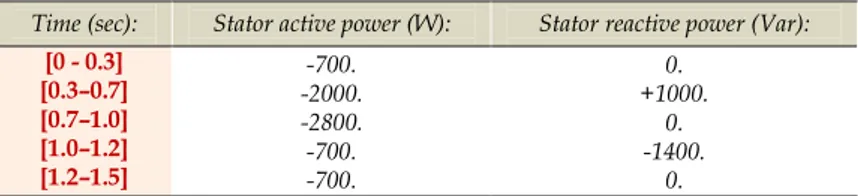
The proposed profiles of the active and reactive power references. ... .45
Recapitulation results for classical control (based on PI). ... .48
Recapitulation results for the proposed control (based on PID) ... .53
Tables of Chapter-3 :
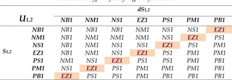
Table.3.1 Table.3.2 Table.3.3 Table.3.4 Table.3.5 Table.3.6 Table.3.7 Table.3.8 Table.3.9 Type-1 fuzzy logic inferences. ... .65Type-2 fuzzy logic inferences ... .67
The parameters of the proposed Neuro-fuzzy controller. ... .68
The proposed profiles of the active and reactive power references. ... .71
Performances results for proposed control based on MRAC using back-to-back SVM converter ... .75
Performances results for proposed control based on T1-FLCusing back-to-back SVM converter ... .80
Performances results for proposed control based on T2-FLC using back-to-back SVM converter ... .85
Performances results for proposed control based on NFC using back-to-back SVM converter ... .90
Wind-system performances (under six proposed IDPC algorithms)... .91
Tables of Chapter-4 :
Table.4.1 Table.4.2 Table.4.3 Table.4.4 Table.4.5 Table.4.6 Excitation switches of NPC’s IGBTs.. ... .101The proposed active and reactive power references ... .104
Results recapitulation for conventional I/OLDC based on PI using two level converter... .107
Results recapitulation for proposed I/OLDC based on MRAC using two level converter ... .112
Results recapitulation for proposed I/OLDC based on MRAC using NPC three level converter ... .117
The proposed references profiles of high power ... .118
Tables of Chapter-5 :
Table.5.1 Table.5.2 Table.5.3 Table.5.4 Table.5.5 Table.5.6 The advantages and disadvantages (difficulties) of the proposed controls (in chapters 3, 4 and 5).. ... .125Incremental sensor connector ... .127
SEMIKUBE connector pin assignment. ... .128
Slave I/O PWM connector (dSPACE1103)... .130
References rotor current variation using L-filter ... .134
LCL Filter's elements with their values ... .137
Tables of Chapter-6 :
Table.6.1 Table.6.2 Table.6.3 Recapitulation results for proposed hysteresis band (HB) performances using 04 cases... ... .157The interfaces / connectors of the SEMIKRON®. ... .157
Page -xv-
List of Abreviation :
DFIG : Doubly Fed Induction Generator.
WECS : Wind Energy Conversion System.
VS-WECS : Variable Speed-Wind Energy Conversion System.
DFIM : Doubly Fed Induction Machine.
HCC : Hysteresis Current Controller.
T1-FLC : Type1-Fuzzy Logic Control.
T2-FLC : Type2-Fuzzy Logic Control.
FIS : Fuzzy Inference System.
ANFIS : Adaptive Neuro-Fuzzy Inference System.
NFC : Neuro Fuzzy Control.
PI : Proportional Integral.
IP : Integral Proportional.
PID : Proportional Integral Derivate.
PWM : Pulse Width Modulation.
SVM : Space Vector Modulation.
AC : Alternating Current.
DC : Direct Current.
ADC : Analog to Digital Converter.
DAC : Digital to Analog Converter.
DSP : Digital Signal Processor.
MPPT : Maximum Power Point Tracking.
P-DPC : Predictive-Direct Power Control.
DPC : Direct Power Control.
FOC : Field Oriented Control.
VOC : Vector Oriented Control.
SMC : Sliding Mode Control.
I/OLDC : Input/Output Linearizing and Decoupling Control
FFT Fast Fourier Transform.
IGBT : Insulated Gate Bipolar Transistor.
DCM : Direct Current Motor.
IM : Induction Motor.
NPC : Neutral Point Clamped.
MRAC Model Reference Adaptive Control (Controller).
LAS : Automatic Laboratory of Setif.
L2EP : Laboratoire de l’Electrotechnique et de l’Electronique de Puissance.
MRAS : Model Reference Adaptive System (Observer).
PF : Power Factor.
MATLAB® : Matrix Laboratory.
THD : Total Harmonic Distorsion.
I/O PWM : Input/output Pulse Width Modulation (dSPACE1103’ or dSPACE1104 card)
Rpm: Revolution per minutes.
PLL: Phase locked loop.
ANN: Artificial neural network
GSC: Grid side converter.
RSC: Rotor side converter.
SA-IDPC Stand-alone-Indirect power control
VS-WT Variable speed-wind turbine
2-LC: Two level converter.
3-LC: Three level converter.
VSI: Voltage source inverter.
FPGA: Field Programmable Gate Array
PSO: Particle Swarm Optimization.
MPC: Model Predictive Control.
GA: Genetic Algorithm.
RTI: Real Time Interface.
IDPC: Indirect Power Control.
FLS: Fuzzy Logic System (FLS)
FOU: The footprint of uncertainty of T2-FLC.
MFs The membership functions
Page -xvi-
B Degree (°). Blade pitch angle.
TSR - Tip Speed Ratio or λ (Lambda).
Cp - Power coefficient.
ρ (Kg/m3). Air density.
v (m/sec). Wind speed.
Rs (Ω). Stator Resistance.
Rr (Ω). Rotor Resistance.
Isq (A). Stator quadrature (or transversal) current component.
Isd (A). Direct axis current of stator.
Irq* & Ird* (A). Rotor reference quadrature (or transversal) and direct current components.
Irq_meas & Irq_meas (A). Rotor measured quadrature (or transversal) and direct current components.
Ls (H). Stator inductance.
Lr (H). Rotor inductance.
Lm (H). Magnetizing (mutual) inductance.
Φrq & Φrd (Wb). Rotor quadrature (or transversal) and direct flux components.
Φsq & Φsd (Wb). Stator quadrature (or transversal) and direct flux components.
Vrq & Vrd (V). Rotor quadrature (or transversal) and direct voltage components.
Vsq & Vsd (V). Stator quadrature (or transversal) and direct voltage components.
Ps, Pr & Pm (W). Stator power, Rotor power and Mechanical power.
Ps* & Qs* (W & Var). Stator reference active power and Stator reference reactive power.
Ps_meas & Qs_meas (W & Var). Stator measured active power and Stator measured reactive power.
Tem, Taero &Tgearbox (N.m). Electromagnetic torque, Aerodynamic torque and Gearbox torque.
Tr & Tvis (N.m). Load torque and Viscous torque.
JG, JTurbine & J (Kg.m2). Generator moment inertia, Turbine inertia and Total inertia.
P - Number of Pole pairs.
Ωmec (Rad/sec). Mechanical speed.
Nr (rpm). Rotor speed.
Nsynchronous (rpm). Synchronous speed (=1500 (rpm)).
G - The gain of the gearbox.
fDFIG (N.m/sec). DFIG’s Friction coefficient.
fTurbine (N.m/sec). Turbine’s Friction coefficient.
S - Slip.
ωs & ωr (rad/sec). Stator and rotor pulsations.
θs, θr & θslip (rad). Stator’, rotor’ and slip angles.
Zs - Stator impedance.
Vdc (V). DC-Link voltage.
Cdc (F) DC-capacitance
RLoad, CLoad & PLoad (Ω, F & W). Load resistance, Load capacitance and Load power.
fgrid, fstator & frotor (Hz). Grid, stator and rotor frequencies.
|Vgrid |& |Vstator| (V). Grid and stator voltage magnitudes.
Is_abc & Ir_abc (A). Stator and rotor currents (line to neutral).
Vs_abc & Vr_abc (V). Stator and rotor voltages (line to neutral).
KP, KI & KD - Proportional gain, Integral gain and Derivative gain.
Isa_meas & Ira_meas (A). Stator and rotor measured current (line to neutral).
Sw (m2). Wind turbine blades swept area (= π*R2).
R (m). Blades diameter of the turbine.
Ig_abc & Ig_abc * (A). Grid measured and reference currents (line to neutral).
Irec (A). Rectifier current.
Cp_max & λ_optimal - Maximum power coefficient and optimal Tip speed ratio (TSR or λ).
Tij & Kij - IGBTs of the rectifier and inverter respectively (i=1, 2 ‘lines’ & j=1, 2, 3 ‘columns’).
Sij - IGBT variable states (1 or 0).
Cf & Lf (F and H) Filter capacitance and filter inductance.
Ifa, Ifb & Ifc (A). Filter currents (in each phase).
Vfab, Vfbc and Vfca (V). Filter voltages (line to line).
IInv, IC & IRotor (A). Inverter (SEMIKUBE) current, capacitance current and rotor current.
VInv & VRotor (V). Inverter (SEMIKUBE) voltage and rotor voltage.
L1 & L2 (H). Inverter side inductance and Rotor side inductance.
R1,R2 & RD (Ω). Inverter (SEMIKUBE) side resistance, Inverter side resistance & Damping resistance
Lf*h(x) - Lie derivative.
T1, T2 & T0 (sec). The SVM switching time duration.
Chapter 0 :
General Introduction
0.1 General Introduction ... 02
0.2 The Main Contributions ... .03
0.3 Thesis Organization ... .06
0.4 Thesis Limitations ... .07
0.5 Scientific Production during the PhD (12 Conference papers, 01 Chapter in Book and 05 Journal Papers) ... 08
0.5.1 International Conferences papers presented in Algeria, France and Bulgaria (2015, 2016 and 2017) ... 08
0.5.2 Chapter in Book (2017) ... 09
0.5.3 Journal Papers (2016) ... 09
0.6 References ... .09
Abstract:
In this chapter a brief general introduction focuses on the well-known topologies of wind energy conversion systems, on proposed controls and generators by the scientific researchers. One part will be devoted to the latest research that has addressed the performance problems of wind systems and their results (in simulation and experimentation). There will also be some arguments that reflect the main proposed ideas in this manuscript, the proposed selections and their applications in simulation and experiments. We present the selecting criteria in particular the type of: generator, controls and theirs application in experimental and simulation studies. Also, we discuss a detailed section on the different contributions of thesis that define the improvement of the proposed algorithms in each chapter. The organization and structure of thesis takes a place in this chapter: chapter one is based on the state of the art of wind systems and their controls, in particular using the doubly fed induction machine. The simulation part is based on three chapters (2, 3 and 4) and the experimental part focuses on chapters (5 and 6). The limitations and problems encountered during the realization of this thesis are well described in the following section (technical problems of simulation and experimentation). After solving problems, very satisfactory (simulation and experimentation) results have been found which reflect the quality of the scientific contribution including more papers of conferences; Journal papers were published during this thesis.