an author's https://oatao.univ-toulouse.fr/27113
https://doi.org/10.1007/978-3-030-62807-9_30
Salas Cordero, Sophia Karolina and Vingerhoeds, Rob A. and Zolghadri, Marc and Baron, Claude Addressing Obsolescence from day one in the conceptual phase of complex systems as a design constraint. (2020) In: IFIP 17th International Conference on Product Lifecycle Management, 5 July 2020 - 8 July 2020 (Rapperswil-Jona,
phase of complex systems as a design constraint
Sophia Salas Cordero1,2 Rob Vingerhoeds1,3 Marc Zolghadri2,3 Claude Baron1,3,4 1 ISAE-SUPAERO, University of Toulouse, France
2 SUPMECA, Quartz Lab, Paris, France 3 LAAS-CNRS, University of Toulouse, France
4 INSA, University of Toulouse, France
Abstract. Obsolescence issues are one of the main costs in the life-cycle of
sus-tainment-dominated systems, those that require support for many decades. Obsolescence not only occurs when a system element becomes no longer availa-ble due to manufacturing updates or production interruption. It also includes the deterioration of the system or component capacity to operate as intended, since it is no longer suitable to fulfil its function, even if it still operates and can be man-ufactured and supported. As such, it also impacts on the “-ilities” (reliability, functionality, etc. …) which can be even traced to legislation changes, for in-stance, the anti-pollution legislation updates for automotive.
Obsolescence has so far been mainly addressed from a reactive point of view. Around 70% of the total product cost is committed as a result of decisions in the early design stages. Late changes induce delays in the life-cycle plan and large increases in cost due to re-design and rework. Knowing the impact of the con-ceptual design phase on life-cycle cost, this paper intends to present a model-based systems engineering approach to proactively assess obsolescence risks. The approach uses obsolescence considerations as constraints during the early design phases, to allow the identification of components potentially at risk of obsolescence. Presenting designers with this information allows them to improve the design, by making it robust and resilient, or to accept the risk and develop an obsolescence mitigation plan.
It will be illustrated with an example from the automotive industry.
Keywords: Obsolescence, Obsolescence Management, Conceptual Design,
MBSE, Automotive.
1
Introduction
Sustainment-dominated systems, those that require long-term support such as aircraft, ships, etc., have obsolescence issues that represent one of the main costs in the life-cycle [1]. For example, obsolescence costs up to $750 million per year to the US Navy [2].
Obsolescence has been mainly managed reactively, meaning that a solution is looked for only once a product discontinuance notice (PDN) has been received. Such an ap-proach leaves little time for solutioning and may therefore be expensive [1]. Evidence [3] [4] shows that 70-80% of total product cost is decided during early design stages [5]. In an effort to address unplanned expenses and knowing the impact of the concep-tual design on the life-cycle cost, this paper intends to present a model-based systems engineering (MBSE) approach to proactively assess obsolescence risk as off the con-ceptual stage of design. Attempting to deal with obsolescence proactively means avoid-ing to wait until the release of a PDN, and to take precautionary measures to ensure the functionality of a system. Late changes in the design of a system cause delays in the life-cycle plan and large increases in cost due to re-design and the work that needs to be re-done.
In order to reduce costs and reduce waiting times, the use of Commercial off-the-shelf (COTS) components has become more and more common as a design solution. Nevertheless, a significant risk of using COTS is parts obsolescence [6]. COTS com-ponents frequently need to be adapted in order to fulfill system requirements. Such custom developments, need to be redone if the COTS vendor upgrades the component, making it an important factor to take into consideration. Whereas technology maturity is an important risk factor, product design adaptations do not seem to be always taken into account as a direct design risk of a system [7].
This paper intends to provide an analysis method that can be utilized since the early stages of design to raise and maintain awareness of what subsystems/parts of the system represent a bigger risk for the development of the system, and thus should be considered critical. Risk calculations will take into account the levels of technology readiness and the interfaces within system’s elements, as well as the number of suppliers of a given technology; as a first approach for obsolescence mitigation in the conceptual stage of design.
The problem with most existing obsolescence management tools is that they are ded-icated only to electronics [1] and do not evaluate the overall design of a system. The proposed method could be utilized as part of a proactive obsolescence management approach for the whole system, to help identify critical components prior to a PDN, considering that to avoid obsolescence the system elements should be available and suitable according to the requirements. The proposed approach is based on a structured way of assessing the risk involved in selecting certain components to fulfil a function.
The paper is structured as follows. Section 2 reviews the concept of obsolescence. Section 3 describes the risk analysis estimation methodology. Section 4 presents the case study and briefly introduces Design Structure Matrices (DSM), and why it was chosen as a modeling method to support this approach. Section 5 discusses the results obtained. In section 6 the paper concludes with a recompilation of the achieved goals and a recommendation for further work on this topic.
2
Obsolescence and System life-cycle
In this paper, the term of obsolescence goes beyond only the availability of a component from a supplier as in [8], referred to as logistical obsolescence in [9]. It intends to deal with functional and technological obsolescence. The former refers to when the “-ilities” become obsolete due to changes in the system requirements or changes in other parts of the system. The latter occurs when more technologically advanced components have become available and older parts are no longer supported. Also, in this paper, mitigation refers to “the measures taken to minimize the impact or likelihood of having an obso-lescence problem” as in [1].
The strategy followed in obsolescence management is usually a combination of dif-ferent mitigation measures. Obsolescence risk can be mitigated by taking actions in three main areas: supply chain, design and planning. While in general the decisions of a vendor do not depend only on one costumer, the design and planning are elements that can be controlled by the costumer from the moment when a product starts to be conceived. This is one of the reasons why it is important to address obsolescence pro-actively from the earliest stages.
At the design stage, it is essential to take into account the number of suppliers and manufacturers that are producing a particular component (implementing a particular technology) before including that component in the bill of materials (BOM). It may for example be necessary to make sure that the components included in the BOM can be provided by multiple suppliers to minimize the number of critical components [1].
Technology manufacturers regularly develop new versions of electronics, software and mechanical parts. These rapid changes lead to technology outpacing systems with long life times, which therefore require legacy parts support [10]. Technology tion is a dynamic field that depends on market demand. A company may favor ing a part that brings high revenues and stop parts with lower revenues, or stop produc-ing parts with higher production risks and/or outdated manufacturproduc-ing technology. In addition, a company might stop the production of a part if they go out of business. The best case scenario would be for an upgraded version of a part to be designed with an open architecture, hence upgraded parts could normally replace previous ones without major issues. The worst case scenario would involve having to design new parts, be-cause a system element abruptly left the market and only had one supplier.
Many authors [11][12][13][14] have pointed out how using open architectures and standard interfaces from the initial system design could help minimize the impact of technology insertion and integration due to the obsolescence or technological evolution of a system. The modularity that these approaches provide with, from a systems design point of view, is a plus. However, it could be seen as a disadvantage for the company that designed the system as more companies would possess the required knowledge to easily make changes to the system and compete for future contracts. Proprietary solu-tions may be favored over open architectures, so to maintain a competitive advantage, although it prevents designing for obsolescence avoidance.
Since open architectures are not compulsory, in the following sections an approach is presented to help estimate the impact of technology insertion and integration at the
design phase, that could lead to obsolescence. A case study from the automotive indus-try will illustrate how the worst case scenario of stopping the production of a part could have been mitigated.
This paper intends to present MBSE analysis tools as an approach to track the status of a system since the early stages of design as part of the Obsolescence Management Plan (OMP) and to answer the following questions:
─ How to address obsolescence since the conceptual design phase when there is barely detailed system information available?
─ How to identify critical components?
As this paper advocates to address obsolescence from the earliest stages of design, this subsection aims at mentioning some of the standard life-cycles to position the concep-tual design phase.
Fig. 1. Life cycle stages comparison of the ISO/IEC 15288 to other life cycle viewpoints [15].
ISO/IEC 15288 [16] identifies six life cycle generic stages: Concept, Development, Production, Utilization, Support and Retirement. The concept stage has a Pre-Concept Exploratory Research Stage which often identifies enabling technologies. The concept stage overall identifies stakeholders’ needs, explores concepts and proposes viable and feasible solutions. As part of this stage mockups may be built (for hardware) or coded (for software), engineering models and simulations may be executed, and prototypes of critical components may be built and tested, to explore the feasibility and risks of the
concepts. These studies include affordability assessment, environmental impact, failure modes, and hazard analysis [15]. Problems identified for individual hardware parts or software modules should be addressed early to minimize the risk that, when these enti-ties are finally designed and verified, they fall short of the required functionality or performance.
As a next step, the development stage takes care of the integration and development, verification and validation (IV&V) activities. The following figure presents inherent design activities per life cycle stage. Concept design and Preliminary design are part of the concept stage, while the development stage comprehends detailed design.
Fig. 2. Design activities per life cycle stage [17].
For NASA [18] as seen in Figure 3 the early stages of the life cycle include pre-formu-lation and formupre-formu-lation phases: pre-phase A, Phase A and Phase B. These phases typical outcomes are:
Pre-phase A (Concept Studies): Feasible system concepts in the form of simulations, analysis, study reports, models, and mockups.
Phase A (Concept and Technology Development): System concept definition in the form of simulations, analysis, engineering models and mockups, and trade study def-inition.
Phase B (Preliminary Design and Technology Completion): End products in the form of mockups, trade study results, specification and interface documents, and prototypes.
Fig. 3. NASA project life cycle phases [18].
Usually there is a confusion regarding what the conceptual stage comprises, versus what the development stage includes. This paper addresses these earliest stages when design decisions are taken.
3
Risk estimation methodology
When calculating risks, there has been an issue regarding the traditional risk calculation presented in the equation 1[19].
Risk = Likelihood × Impact (1)
An important issue is how to objectively evaluate the likelihood and the impact. Both [20] and [7] use methodologies to avoid the subjectivity of risk likelihood and impact. They propose risk estimation frameworks that include systems architecture considera-tions for product development and technology integration programs. In this paper ob-solescence is intended to be addressed since the early design stages; risk assessment is very important.
[20] and [7] manage to utilize an objective measure of risk likelihood and impact. The objective measurement parameters are technology readiness levels (TRLs) for the likelihood and the number of interfaces within system elements for the impact. The level of a product design adaptation, meaning the degree of certainty regarding the de-sign, implementation and capabilities of a certain technology or part can be linked to TRLs as a system development risk, since it involves the aspects of integration and technology maturity. The more mature a system is, the less uncertainties there are on the design.
NASA’s TRLs offer a well-documented and widely used scale for measuring the degree of maturity in a given component according to [7]. TRLs can be determined with the help of a Technology Readiness Assessment (TRA)[21]. TRA is a formal, system-atic, metrics-based process and accompanying report that assesses the maturity of crit-ical hardware and software technologies to be used in systems. The TRA is a document required in order to transition between phase B and C/D (NASA’s life cycle). TRLs are defined as standardized levels ranging from 1 to 9 [6]. Their definitions are presented in Figure 4, TRL 1 is the less mature level and the one that represents more risks while TRL 9 is the most mature and represents less risks as presented by [20].
Fig. 4. TRLs definitions from NASA Systems Engineering Handbook [18].
Design/System changes propagate between components through their interfaces [3]. Hence the degree in which a change in the system will impact the system itself depends on the number of interfaces the system element has with other system elements. In this
paper the interfaces taken into account are the first degree undirected interfaces. It takes into consideration if interfaces are present between the system’s parts or not (which can be seeing as a simplified binary approach) and limits the approach to direct connections between the systems parts. They are undirected because the impact of the change of subsystem A on subsystem B is consider equal to the impact of the change of subsystem B on subsystem A. At the start of the conceptual design stage, a lot of system infor-mation is missing since a lot of design decisions have not been made. That is why as a first approach, first degree undirected interfaces are considered to be adequate. Subse-quently, when in the next life-cycle stages more information is available, the estima-tions can be adapted and eventually extended to directed connecestima-tions so to take it into account more precise and updated information.
Widely used in Systems Engineering (SE) and project management, Design Struc-ture Matrices (DSM) were chosen to model the interfaces. The DSM is an NxN matrix that maps the interactions among the set of N elements, is a network modeling tool used to represent the elements comprising a system and their interactions, thereby highlight-ing the system’s architecture or designed structure. DSMs are particularly well suited for applications in complex systems development and used more often in the area of engineering management [22].
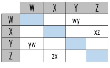
In this paper, the convention used to represent the information on the DSM is inputs in rows (IR). As the name mentions it, the inputs of a discipline are the elements in its row, the elements of the DSM in this case are W, X, Y and Z (Fig. 5). For practical purposes in this work, the convention inputs in columns (IC) would look the same since as mentioned above, the interfaces taken into account are first degree undirected inter-faces. This means that in the DSM example in fig.5, ‘wy’=‘yw’ and ‘zx’=‘xz’. Since only undirected interfaces are being considered there is no difference between the in-puts to Y from W or the inin-puts from Y to W. Naturally the value of ‘zx’ and ‘xz’ equals the number of interactions between X and Z.
Fig. 5. DSM example
The TRLs and number of interfaces are scaled from 1 to 5 as a risk input calculation in this paper, subsequently the risk is scaled for a maximum of 25 and minimum of 1, as in [20] with the following equation:
𝑋𝐵=
(𝐿𝐵−𝑈𝐵)×𝑋𝐴+𝑈𝐵×𝐿𝐴−𝐿𝐵×𝑈𝐴
𝐿𝐴−𝑈𝐴 (2)
Where:
XB - Value in scale B, UA - Upper limit of scale A, UB - Upper limit of scale B, LA - Lower limit of scale A, LB - Lower limit of scale B.
For example, a TRL of 7 in a scale from 1 to 9 (scale A) needs to be recalculated in the scale from 1 to 5 (scale B) as a risk input calculation. Which would mean that: XA= 7 (TRL level) and the TRL scale: UA= 1, LA= 9 and the new scale: UB =5, LB= 1 and substituting in the equation 2 the value for XB then equals to 2.
4
Case Study
Engine management, responsible for the control of the engine to so be able to provide the necessary torque for driving at the right moment, but also to provide energy for the other vehicle subsystems (climate control, etc.), is since the 1990’s done with electronic control systems. A comprehensive set of sensors and actuators, and an electronic con-trol unit, interpret the request of the driver, the current engine and vehicle conditions and allow for controlling several of the engine parameters.
Within engine management the detection and control of knock is an important func-tionality. Knock is an uncontrolled and unwanted self-ignition phenomenon for internal combustion engines with spark ignition that occurs when a high pressure is reached (close to the maximum torque) and that is triggered before or after the spark. Knock limits the good efficiency of internal combustion engines, that depends on high com-pression ratio and a proper spark timing. Knocking occurs when there is a spontaneous ignition of unburned air-fuel mixture that occurs after ignition by spark plug [23]. The very rapid heat release implied with this abnormal combustion generates shock waves. Knock consequences are harmful, from excessive emission of pollutants, efficiency de-crease, to engine damage. Its detection and prevention are thus an important part of engine control.
For economic reasons, the direct method of measuring knock by in-cylinder pressure transducers is usually replaced by exploiting the vibration signal from one or more pi-ezoelectric sensors mounted on the engine block surface. Knock being constituted of several resonances determined by cylinder geometry, the standard treatment is to apply a band-pass filter followed by computation of signal energy in a predefined time win-dow. The result is compared to base engine noise to make a decision whether knock is present or not. Parameters of the treatment like the resonance to choose, filter frequency and time window are determined for each engine type during calibration phase.
Once knock has been detected, knock control algorithms can be used to bring the engine to safe operation mode. Usually, this control is accompanied by an adaptive control functionality that allows the engine management system to adapt its ignition set-up in function of changing parameters, such as the fuel type used.
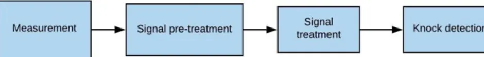
Looking at the engine knock management functional diagram (Fig. 6), there are broadly four functions that can be identified:
● knock detection measurement (instrumentation)
● a knock signal pre-treatment (e.g. in smart ignition coils, before the signal goes via wiring to the engine management system)
● a knock signal hardware entry stage in the engine management system ● a knock detection
Fig. 6. Engine Knock management functional diagram
For knock detection, different means can be envisaged: vibration detection as men-tioned above, ionization current analysis, etc. In function of the choice of the instru-mentation for the actual impleinstru-mentation, a knock signal pre-treatment may be neces-sary or not. For example, a piezoelectric transducer can undergo without such pre-treat-ment, whereas ionization current analysis may greatly benefit from such a pre-treatment with smart ignition coils. Of course, these options have different benefits and disad-vantages.
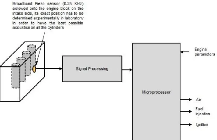
For the hardware entry-stage different options can be thought of, like for example (see Fig. 7):
● dedicated Integrated Circuit (IC) ● general-purpose programmable IC
● software solution in the main microprocessor.
Fig. 7. Generic System architecture of the Engine Knock Management System
In the current proposed case-study, the design of the knock detection functionality is explored and the data is based on a real industrial situation from the late 1990 – early 2000s. At the design stage of this system (some years earlier), several System Archi-tectures (SA) were considered and finally one was selected. The selected SA includes a piezo-electric transducer, that was used for the actual measurement, no pre-treatment,
a dedicated IC used for the hardware entry-stage and a regular software solution for the actual detection. (see figure 8)
Fig. 8. Realization example of a knock detection functionality for a 4-cylinder in-line gasoline
engine.
The dedicated IC was purchased from an external supplier. Because of the complex functionality inside the IC that was based on little by little outdated electronics, it was complex to produce and became costly. At some point, the supplier announced the stop of this IC’s production and offered a last-time buy to all of its customers. As this par-ticular IC bare-dies could not be stored for a long time and this last-time buy did not leave a lot of time to the automotive suppliers to find alternative solutions. The dedi-cated IC was a critical element; could it have been foreseeing earlier in the design of the system? As the design of the IC was proprietary to the manufacturer, no double sourcing had been possible.
5
Results and discussion
Three architectures are presented here for consideration out of the many possible, for practical reasons they will be called Architecture A, B, and C:
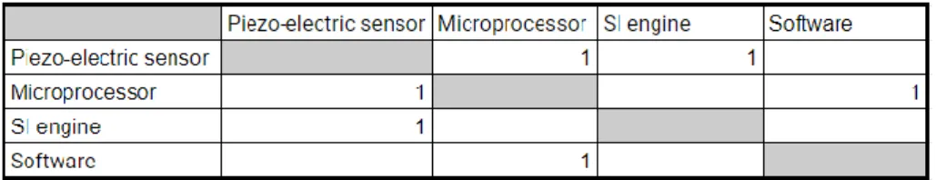
a. Consists of a piezo-electric sensor, a microprocessor, an engine, and a dedicated IC as seen in the DSM (Fig. 9)
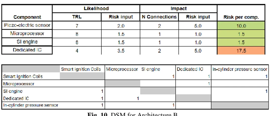
b. Consists of a piezo-electric sensor, a software solution (chosen as the signal treat-ment component), a microprocessor, and the engine. (Fig. 10)
c. Consists of an in-cylinder pressure sensor and smart ignition coils (that allow for data pre-processing), a microprocessor, an engine, and a dedicated IC. (Fig. 11)
Fig. 9. DSM for Architecture A.
The results in table 1 were calculated with the help of equations 1 and 2 and the avail-able information in the DSM for architecture A (fig. 9). Firstly, the likelihood and im-pact component of the risk should be transitioned to the same scale (in this case from 1 to 5 with equation 2) as explained at the end of section 3, and then the risk can be calculated per component (equation 1).
To calculate the impact as a risk input utilizing equation 2, the number of interfaces a component has is needed. This information is available in the DSM (fig. 9). For in-stance, the dedicated IC and the piezo-electric sensor have 2 interfaces when the mi-croprocessor and SI engine have 1. Therefore, the number of interfaces are a scale from 1 to 2 and need to be recalculated in the scale from 1 to 5 as a risk input calculation. Which would mean that: XA= 2 (number of interfaces) and the interface scale: UA= 2, LA= 1 and the new scale: UB =5, LB= 1 and substituting in the equation 2 the value for XB then equals to 5.
Table 1. Impact versus likelihood per element Architecture A.
Fig. 10. DSM for Architecture B.
Table 2 and 3 were calculated correspondingly with the DSMs available in figure 10 and 11.
Fig. 11. DSM for Architecture C.
Table 3. Impact versus likelihood per element Architecture C.
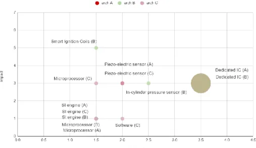
In figure 12 the size of the bubble of the chart represents the risk of depending on solely one supplier for a component. Also in this figure in order to compare all the architec-tures in one chart, the initial scale for the impact was taken as 1 to 3 for all the archi-tectures and transform to the scale of 1 to 5.
In the case of architectures A and B, the dedicated IC comes out as a critical com-ponent, with the highest likelihood of risk and only one supplier as it can be seen in Fig. 12. In addition, the TRL is estimated to be low, as at the time of developing the solution, the IC was not yet qualified for automotive applications, which meant an ad-ditional risk. A component designed for an environment different to the one in which is planned to be used automatically possesses a TRL of 4. The assumption that the TRL would be 9 in this case is not correct since the component was never validated in the automotive relevant environment.
The dedicated IC not only has the higher level of likelihood but also has only one supplier, which is a risk to consider as mentioned before. It may be necessary to make sure that components included in the BOM can be provided by multiple suppliers to minimize the number of critical components [1]. From this point of view Architecture A may not be a good option.
The components that integrate Architecture C have more than one supplier and hence the risk per component is not outgrowing the others. The software solution would have been a good option, but at the time of developing the system due to technology con-strains it would have not been possible to be applied because of economic reasons. In figure 12 it can be observed also how when comparing several architectures, the impact index is intrinsic to the architecture it is in. Whilst the microprocessor possesses a TRL of 8 (likelihood of 1.5), the impact is proportionate to the number of connections which is higher for the microprocessor in Architecture C.
Fig. 12. Impact versus likelihood per element per architecture
*Technology needed to implement the software solution was not available at the moment. Fig. 13. Main architectures’ element technology comparison.
6
Conclusions and Future Work
This paper presents an MBSE analysis method as an approach to track the status of a system since the early stages of design as part of obsolescence management, in order to maintain awareness of what subsystems/components of a system represent a bigger risk, and thus should be considered critical. The method is able to be used without de-tailed information about the types of interfaces within a system, and is able to compare possible architectures. This paper presents an example of a real-life case study, and illustrates how knowing a priori the risk that the dedicated IC represented for architec-ture A, the need for an obsolescence management plan could have been foreseen; and initiated at this phase as an obsolescence mitigation measure, in order to tackle the ob-solescence proactively.
The presented method is accessible and feasible to implement. Nevertheless, this risk assessment as well as a formal TRA [21] complements but does not preclude the sys-tem’s engineer and program manager’s role to determine which trade-offs are consid-ered acceptable in order to ensure the development of a system.
Technology Readiness Levels (TRLs) were used to rate the likelihood. While the number of interfaces represents the complexity and therefore the potential impact of the risk on the whole system. The likelihood and impact of the risk were objectively rated, for which this approach provides a good option to objectively obtain an evaluation of the risk a component might bring when developing a system.
System elements need to carefully be considered in order for a system not to become obsolete since the design phase. The so called heritage systems should be paid particular attention since they are normally used in architectures and environments different to the ones for which they were designed. Which is precisely the case of the dedicated IC, the assumption of it possessing TRL 9 would not be correct as the component was at the time of the concept stage of the function development, not yet validated in a relevant automotive environment, and therefore is TRL 4. It is also very important to consider if the component has only one supplier, because this constitutes a huge risk as men-tioned above. Which was yet again the case of the dedicated IC.
DSMs were chosen as the modeling tool taking into account the possibility of ex-panding the approach in the future to take into consideration not only undirected inter-faces but also directed, which could be possible when more system information is avail-able.
During the early stages of design, alternative SA options and the results of technol-ogy maturation are reviewed. The technoltechnol-ogy maturation process can help identify re-quirements and development routes that are not feasible. While avoiding the use of high risk critical components can prevent from unnecessary unplanned expenses due to re-design and rework further down the life cycle.
As a recommendation for further work, it is advised to evaluate the impact of early risk analysis of the design on the life cycle of a system. To know if all the design deci-sions were made taking into consideration the future events that accepting a risk might signify. Another recommendation would be to observe how the design changes prop-agate when utilizing this method during the conceptual stage on the rest of the system development whilst actively tracking the risks for each design decision made.
References
1. Romero Rojo FJ, Roy R, Shehab E (2010) Obsolescence management for
long-life contracts: State of the art and future trends. Int J Adv Manuf Technol 49:1235–1250. https://doi.org/10.1007/s00170-009-2471-3
2. Adams C Getting a Handle on COTS Obsolescence - Avionics.
https://www.aviationtoday.com/2005/05/01/getting-a-handle-on-cots-obsolescence/. Accessed 15 Jan 2020
3. Clarkson PJ, Simons C, Eckert C (2004) Predicting Change Propagation in Complex Design. J Mech Des 126:788. https://doi.org/10.1115/1.1765117
4. Giffin M, De Weck O, Bounova G, et al (2009) Change Propagation Analysis
in Complex Technical Systems. J Mech Des .
https://doi.org/10.1115/1.3149847
Design: A Review of the Literature. In: Conference: International Conference on Education, Management and Computing Technology (ICEMCT-15). Atlantis Press, Tianjin, pp 1679–1691
6. Lebron RA, Rossi R, Foor W (2001) Risk-Based COTS Systems Engineering
Assessment Model: A Systems Engineering Management Tool and Assessment Methodology to Cope with the Risk of Commercial Off-the-Shelf (COTS) Technology Insertion During the System Life Cycle
7. Garg T;, Eppinger S;, Joglekar N;, Olechowski A USING TRLS AND
SYSTEM ARCHITECTURE TO ESTIMATE TECHNOLOGY
INTEGRATION RISK. In: Product, Services and Systems Design. pp 301–310
8. Dowling T (2001) Planning For Change With A Holistic View Of The System
9. Bartels B, Ermel U, Pecht M, Sandborn P (2012) Strategies to the Prediction,
Mitigation and Management of Product Obsolescence
10. Lebron RA, Rossi R, Foor W Risk-Based COTS Systems Engineering
Assessment Model: A Systems Engineering Management Tool and Assessment Methodology to Cope with the Risk of Commercial Off-the-Shelf (COTS) Technology Insertion During the System Life Cycle
11. Devereaux JE, Hale P OBSOLESCENCE: A SYSTEMS ENGINEERING
AND MANAGEMENT APPROACH FOR COMPLEX SYSTEMS MASSACHUSETTS INSTIft1TE By OF TECHNOLOGY
12. Michael Ostrovsky B, Asker J, Bulow J, et al Stability in Supply Chain Networks. https://doi.org/10.1257/aer.98.3.897
13. Young D (2000) New Approaches to Processor Lifecycle Management
14. Buratti M, Brusco D Del, Difesa A Strategies to Mitigate Obsolescence in Defense Systems Using Commercial Components
15. INCOSE (2007) Systems Engineering Handbook: A Guide for System Life
Cycle Processes and Activities. International Council on Systems Engineering (INCOSE)
16. ISO/IEC/IEEE (2015) 15288:2015 - Systems and Software Engineering –
System Life Cycle Processes
17. Brazier F, Langen P van, Lukosch S, Vingerhoeds R (2018) Design,
Engineering and Governance of Complex Systems. Proj People – Mastering Success 34–59
18. NASA (2017) NASA Systems Engineering Handbook, SP-2016-6105 Rev2.
12th Media Services
19. ISO (2018) 31000:2018 Risk management
20. Arroyo IH, Fortin C (2018) Technological and Complexity Risk Analysis For
Set Based Design Evaluation. In: 2018 IEEE International Systems Engineering Symposium (ISSE). IEEE, pp 1–5
21. (2009) Technology Readiness Assessment (TRA) Deskbook
22. Eppinger SD, Browning TR (2012) Design structure matrix methods and
applications. MIT Press
![Fig. 1. Life cycle stages comparison of the ISO/IEC 15288 to other life cycle viewpoints [15]](https://thumb-eu.123doks.com/thumbv2/123doknet/2939999.79024/5.892.210.687.488.864/fig-life-cycle-stages-comparison-iso-cycle-viewpoints.webp)
![Fig. 2. Design activities per life cycle stage [17].](https://thumb-eu.123doks.com/thumbv2/123doknet/2939999.79024/6.892.226.670.403.503/fig-design-activities-life-cycle-stage.webp)
![Fig. 4. TRLs definitions from NASA Systems Engineering Handbook [18].](https://thumb-eu.123doks.com/thumbv2/123doknet/2939999.79024/7.892.204.687.764.936/fig-trls-definitions-from-nasa-systems-engineering-handbook.webp)