an author's https://oatao.univ-toulouse.fr/23413
https://doi.org/10.1109/DASIP.2016.7853824
Hafidhi, Mohamed Mourad and Boutillon, Emmanuel and Dion, Arnaud Demo: Localisation in a faulty digital GPS receiver. (2016) In: Conference on Design and Architectures for Signal and Image Processing (DASIP 2016), 12 October 2016 - 14 October 2016 (Rennes, France).
Demo: Localisation in a faulty digital GPS receiver
Mohamed Mourad Hafidhi and Emmanuel Boutillon
Lab-STICC, UMR 6582, Universit´e de Bretagne Sud 56100 Lorient, France
email: [email protected], [email protected]
Arnaud Dion
Universit´e de Toulouse, ISAE Toulouse, France email: [email protected]
Abstract—The increase in integration density and the require-ment of low power supplies to reduce energy consumption can make circuits more and more sensitive to hardware errors. The loss of robustness increases with process/voltage and temperature (PVT) variations. This demo presents a platform used first to implement a noiseless GPS receiver algorithm. Redundant mech-anisms can be added, then, to the design to make the GPS receiver more resilient against upset errors due low supply voltage. The platform can be used, so, to evaluate the performance and the complexity of the proposed mechanisms.
I. INTRODUCTION
Global Positioning System (GPS) receivers are heavily used in mobile contexts, and there is motivation to minimize power consumption and maximize battery life in these devices. Power consumption and device lifetime can be improved by operating at minimal supply voltage, which increases the likelihood of hardware errors. The loss of robustness increases with the advancement of CMOS technology in combination with process/voltage/temperature (PVT) variations [1].
The RELIASIC (Reliable ASIC) project, [2], investigates the fault tolerance in the GPS context starting from a standard GPS application and adding some redundant mechanisms to allow the GPS receiver to be tolerant to hardware errors due to low voltage supply. An Application-specific integrated circuit (ASIC) will be designed with two versions of the GPS re-ceiver: the standard version, and a complex version where fault tolerant techniques are added to make the GPS receiver more tolerant to hardware errors. This demo presents a platform used first to implement the standard GPS receiver algorithm, and, then to evaluate the performance and the hardware complexity of a proposed technique for error tolerance.
II. GPS OVERVIEW
A GPS is a well known-technology that allows determining both the physical position and the absolute time of a receiver. To do so, there are two essential and sequential processes: the acquisition and the tracking process [3]. The acquisition process is the process by which the receiver identifies which satellites are in view. It is a three-dimensional search to determine the GPS satellite identifier, the code phase, and the carrier frequency offset due to Doppler Effect. Since satellites are in continuous motion, the distance between any satellite and the receiver is dynamic. Besides to that, the carrier frequency of the received signal is also constantly changing in time due to Doppler shifts. Therefore, once acquired, GPS
Fig. 1. Photograph of the FPGA test setup
signals have to be tracked over time to be able to extract the correct navigation data.
III. PLATFORM DESCRIPTION
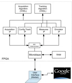
The implemented platform in the case of a standard GPS receiver can be split into three main parts: the user interface, the signal source file and the FPGA target.
• User interface: This represents the space from where the FPGA is controlled. The interface is written by MATLAB software. Functionality given by the user interface are: Program the FPGA with new codes, launch simulations, plot results, display position of a GPS receiver over time using Google Earth software...
• Signal source file: Signal received from more than 4 GPS
satellites, over a significant period of time, are stored in a file. This file is added then in the memory of an FPGA to replace a real-time receiving process of a GPS receiver.
• FPGA target: this part will contain the hardware
de-scription of the acquisition and the tracking algorithms for a GPS receiver. It contains also a micro-blaze that manages the communication between the user interface and the hardware description of the GPS receiver. The platform was tested in the Virtex-6 FPGA ML 605 device as presented in fig. 1. The GPS receiver algorithm was also designed with the MATLAB high level software in order to compare results from FPGA with MATLAB results in terms of position given by the GPS receiver.
IV. FAULT TOLERANCE EVALUATION USING THE PLATFORM
The platform described above is used to evaluate techniques proposed for fault tolerance in the GPS context. The stored
Fig. 2. Diagram of the test setup
source file is processed by a noiseless GPS receiver imple-mented inside the FPGA to generate the set of successive es-timated positions X(t)t=1...T. Then the noiseless GPS receiver
is replace with a noisy GPS receiver and another simulation is launched using the same source file to generate sets of noisy position ˜XN(p, j), j = 1..Q. The model of noise used in this
case is very simple. For each active tracking module, every output of the faulty component is assumed to be exact with a probability (1 − p) or to be faulty with a probability p. In case of faulty result, a random number of bits at the output of the faulty module are flipped.
As an example, it has been shown in [4] that the impact of errors that appear when computing the estimation of the Doppler offsets in a GPS application can be greatly reduced by tuning appropriately the carrier filter bandwidth. To illustrate the noise effect on the GPS receiver output, positions given by the noiseless and the faulty receivers are compared in fig. 3. In this figure, the noiseless position X(t) is shown with color orange. We represent, then with the red color, the faulty position of the noisy GPS receiver when the fault tolerant technique was not used. Finally, the position given by the faulty GPS receiver, after adding the fault tolerant mechanism to the design, is appeared with the blue color.
V. CONCLUSION
In this demo we present an implementation of the standard GPS receiver in the Virtex-6 FPGA ML 605 device. This system evolves also a user interface in MATLAB and a micro-blaze to manage the communication between the FPGA target and the user interface. This platform is used then to evaluate the performance of a fault tolerant technique that has been proposed to make the carrier discriminator in the GPS receiver more tolerant to hardware errors.
FUTUREWORKS
Additional works are progressing to replace the signal source file with a real-time receiving process of a GPS receiver
Fig. 3. Position given by a noiseless GPS receiver X(t) (color orange), by a faulty GPS receiver without adding the fault tolerant technique (color red), by a faulty GPS receiver when using the fault tolerant technique (color blue), displayed using Google earth
in order to have a complete GPS receiver (Radio Frequency and digital processes). Although, fault tolerant techniques that have been proposed in [5], [6] and [7] to protect, respectively, the Gold code generator, the the Numerically Controlled Oscillator and the correlation will be implemented in the noisy receiver to evaluate the robustness of the complete GPS receiver against transient errors. An ASIC will replace the FPGA target once the study of the trade-off between the complexity and the performance of the GPS receiver is achieved.
ACKNOWLEDGMENT
This work was funded by French government sponsors COMIN Labs and the National Research Agency in the “Investing for the Future” program under reference ANR-10-LABX-07-01 and the Brittany Region. The authors would like to thank the Institut Superieur de lAeronotique et de lEspace (ISAE) for sharing with us VHDL codes of the GPS receiver application.
REFERENCES
[1] S. Borkar, “Tackling variability and reliability challenges,” IEEE Des. Test, vol. 23, no. 6, pp. 520–520, Nov. 2006. [Online]. Available: http://dx.doi.org/10.1109/MDT.2006.156
[2] [Online]. Available: http://www.reliasic.cominlabs.ueb.eu/
[3] J. B.-Y. Tsui, Fundamentals of Global Positioning System Receivers. Wiley-Interscience, 2000.
[4] M. M. Hafidhi and E. Boutillon, “Improving the performance of the carrier tracking loop for gps receivers in presence of transient errors due to pvt variations,” in The International Workshop on Signal Processing Systems (SIPS), submitted in May 2016, pp. 1–6.
[5] M. M. Hafidhi, E. Boutillon, and C. Winstead, “Reliable gold code generators for gps receivers,” in 2015 IEEE 58th International Midwest Symposium on Circuits and Systems (MWSCAS), Aug 2015, pp. 1–4. [6] M. Dridi, M. M. Hafidhi, C. Winstead, and E. Boutillon, “Reliable nco
carrier generators for gps receivers,” in Design and Architectures for Signal and Image Processing (DASIP), 2015 Conference on, Sept 2015, pp. 1–5.
[7] M. M. Hafidhi, E. Boutillon, and C. Winstead, “Reducing the impact of internal upsets inside the correlation process in gps receivers,” in Design and Architectures for Signal and Image Processing (DASIP), 2015 Conference on, Sept 2015, pp. 1–5.