To cite this document:
Rousseau, Adrien and Darbon, Stéphane and Girard, Sylvain and
Paillet, Philippe and Bourgade, Jean-Luc and Goiffon, Vincent and Magnan, Pierre and
Lalucaa, Valerian and Hamel, Matthieu and Larour, Jean Vulnerability of optical
detection systems to megajoule class laser radiative environment. (2012) In: SPIE
Photonics Europe, 16 April 2012 - 19 April 2012 (Brussels, Belgium).
O
pen
A
rchive
T
oulouse
A
rchive
O
uverte (
OATAO
)
OATAO is an open access repository that collects the work of Toulouse researchers and
makes it freely available over the web where possible.
This is an author-deposited version published in:
http://oatao.univ-toulouse.fr/
Eprints ID: 11402
Any correspondence concerning this service should be sent to the repository
administrator: [email protected]
Vulnerability of optical detection systems to megajoule class laser
radiative environment
A. Rousseau*
a, S. Darbon
a, S. Girard
a, P. Paillet
a, J. L. Bourgade
a, V. Goiffon
b, P. Magnan
b,
V. Lalucaa
b, M. Hamel
c, J. Larour
da
CEA, DAM, DIF, F-91297 Arpajon, France;
bUniversité de Toulouse, ISAE, 10 avenue E. Belin,
F-31055, Toulouse, France;
cCEA, LIST, Laboratoire Capteurs et Architectures Electroniques,
F-91191, Gif-sur-Yvette Cedex, France;
dLaboratoire de Physique des Plasmas, UMR 7648,
Ecole Polytechnique, UPMC, CNRS, 91128 Palaiseau, France
ABSTRACT
The Laser MegaJoule (LMJ) facility will host inertial confinement fusion experiments in order to achieve ignition by imploding a Deuterium-Tritium filled microballoon [1]. In this context an X-ray imaging system is necessary to diagnose the core size and the shape of the target in the 10-100 keV band. Such a diagnostic will be composed of two parts: an X-ray optical system and a detection assembly. The survivability of each element of this diagnostic has to be ensured within the mixed pulse consisting of X-rays, gamma rays and 14 MeV neutrons created by fusion reactions.
The design of this diagnostic will take into account optics and detectors vulnerability to neutron yield of at least 1016. In this work, we will present the main results of our vulnerability studies and of our by-system and hardening-by-design studies.
Keywords: APS, CCD, CMOS, Laser MegaJoule, optical relay, scintillator, vulnerability
1. INTRODUCTION
X-ray imaging diagnostics are fundamental for inertial confinement fusion experiments in order to achieve ignition. Indeed, reasons for failures might be understood by evaluating the quality of implosion symmetry. This diagnostic will record in harsh environment the core size and the shape of a microballoon filled with cryogenic Deuterium-Tritium. The radiative surrounding will be induced by fluxes of neutrons and gamma rays which can affect diagnostic performances.
(a) (b)
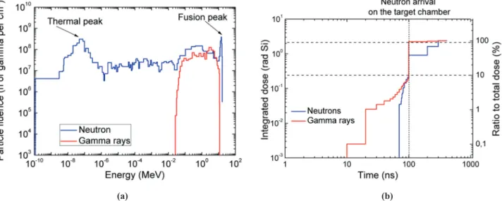
Figure 1. Simulation of radiative environment inside the 10 meters diameter chamber, at 4 meters from Target Chamber Center (TCC) for neutron yield of 1016. (a) Neutrons and gamma rays spectra. (b) Cumulated dose versus time.
1.1 The radiative environment
The Deuterium-Tritium target yields a large amount of neutrons whose energy distribution has its maximum at 14 MeV. The facility equipment, mainly the wall of the target chamber, would modify the initial neutron spectrum due to inelastic scattering. Gamma rays would be generated in addition to neutrons by two main reactions: DT fusion reactions might emit quasi monochromatic 16.8 MeV gamma rays, the (n, n’ ) reactions will induce an increasing gamma ray production (fig.1a).
The interaction of fusion neutrons on the spherical target chamber wall at 5 m from the source placed at Target Chamber Center (TCC) creates a huge gamma ray burst around 100 ns after the main fusion reactions inside the fuel. Consequently, the dose dramatically increases from 0.1 to 2.4 rad(Si) (fig.1b) at a very high dose rate from 5.105 to 5.108 rad.s-1. The dose then decreases gradually. For a first estimate, a dose monitoring system has been exposed to typical 1013 neutron yield on the OMEGA Laser facility (Laboratory for Laser Energetics, University of Rochester): 90% of dose is generated in the first 370 ns of the experiments. After few tens of nanoseconds, dose rate downs to low perturbing background.
(a) (b)
Figure 2. (a) Dose monitoring at OMEGA facility. (b) Experimental measurements of dose and dose rate time dependence at 5m from the target chamber center (chamber diameter 3.75 meters).
1.2 Two detection schemes for minimizing effects of radiative environment
Previous simulations and experiments on laser facilities have shown that the use of detectors inside the target chamber will at least drastically reduce their performances, at worst destroy them [2].
One way of protecting the diagnostic from particles generated during the implosion consists in setting the image sensor in a shielded box. Thanks to a shielding capability up to 28 tons, the detector will face a radiative background reduced at least 10 times. We strategically chose to separate the imaging system from the recording stages. The core of the implosion will be imaged on a scintillator [3] through an X-ray optical system. Then the visible light emitted by the scintillator is easily transferred through a 7 meter long optical relay to shielded box and focused on a detector.
If the shielding significantly reduces the dose, it is not sufficient by itself. A good way to avoid the neutron related burst induced degradation is to choose one of the two following schemes:
- The first one will benefit from the relatively quiet radiative background of the first 100 ns of the experiment, the image must be recorded in this temporal window thanks to a fast detection scheme [4]. - The other one consists in recording the image after the dose has faded away. As figure 1(a) shows, for
megajoule class lasers, 90% of gamma ray and neutron dose is delivered in less than 300 ns. Thus a
TCC
5 m
low decay time scintillator (around 1 ms) with a minimum sensitivity to the radiative environment would allow to record the image after the first 500 ns of the experiment.
.
Figure 3. Diagnostic equatorial implantation in the LMJ facility.
2. VULNERABILITY OF FAST DETECTION SCHEME
2.1 Vulnerability of optical relayThe optical relay is one of the most vulnerable elements regarding the fast detection scheme. Because of the harsh environment, optical glasses yield parasitic lights generated by some dose synchronous scintillation processes. Among them, Cerenkov radiation is emitted when charged particles travel through a transparent medium with velocity higher than phase velocity of light. The intensity of the phenomenon depends on the optical index of the medium and consequently on its chemical composition, its temperature, its purity type and concentrations. In addition to scintillation process, radiative environments lead to radiation-induced attenuation in glass [5] that modifies the initial spectrum of parasitic light. Consequently, one of the major issues about the relay conception consists in identifying and eliminating glass-based optics with high sensitivity to radiations.
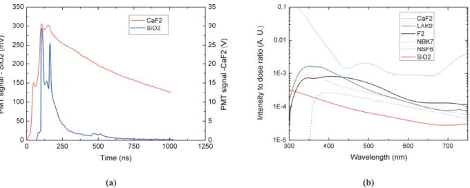
(a) (b)
Figure 4. Typical behavior observed under irradiation. (a) Glass scintillation decay time under 1013 neutron yield. (b) Parasitic light spectrum generated under hard X-ray (100 keV – 18 MeV) continuous generator.
The Omega Laser Facility is a fundamental tool for studying the behavior of glasses under irradiation as the DT shot campaigns mimic the perturbing source expected at early times on LMJ and NIF. The amount of parasitic light generated by standard optical glasses and fiber bundles was quantified using a set of multipliers installed inside the Target Bay Area at 5 meters from TCC. Glasses presented different behaviors in terms of the amount of emitted light and decay time. As a result of such studies, glasses that are prone to scintillation have been identified and their use must be minimized as much as possible on megajoule class laser diagnostic systems.
A commercial optical fiber bundle is a particularly relevant case of vulnerability. The impact of parasitic light emitted by fibers under irradiation on a 16 bits CCD back illuminated has been calculated thanks to measurements performed at OMEGA facility. The background level has been estimated at around 30% of the CCD dynamic for a 2 m long fiber bundle. The linearity of parasitic light intensity versus bundle length has also been checked on OMEGA. Consequently a 7 meter long optical fiber bundle as an optical relay will cut the acquisition dynamic drastically.
2.2 Vulnerability of an optical analyzer
The fast detection scheme needs a 100 ns integration time. A light amplifier or a gated optical imager might be used as optical shutter system for such a short integration time. These devices are composed of three stages: a cathode which converts visible light into electrons, a polarized micro-channel plate for amplification and a phosphor for reconversion into light. In addition to time-controlled integration, these systems amplify the signal but also the noise related to the harsh environment.
The level of nuclear background generated on OMEGA facility leads to visible effects on recording devices which can be simulated [6]. A standard imaging system, composed with a light amplifier and a cooled CCD, has been exposed to high neutron yield shots at 5 meters from TCC to determine the induced background level. Contributions of each part of the recording stage have been successfully identified thanks to different masks positioned between the various optical interfaces.
(a) (b)
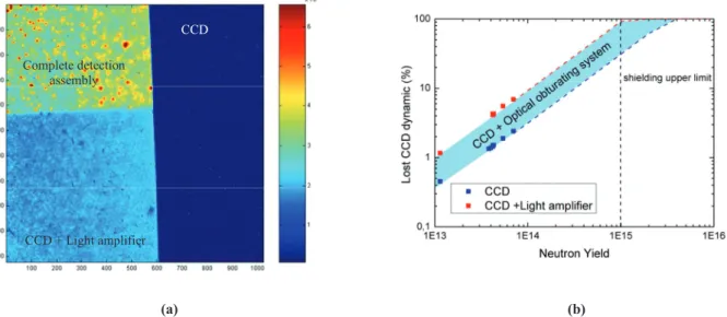
Figure 5. Behavior of fast recording device under nuclear background. (a) Example of background level generated under 1013 neutron yield on an optical analyzer at 5 m from TCC. (b) Parasitic signal intensity converted into CCD dynamic.
As a result, the increasing background level of recording device has been clearly observed. The CCD linearity versus nuclear background has been checked with neutron and gamma ray sources in the dose range expected with the LMJ facility from 0.1 to 10 mrad, in order to confirm the extrapolated curves. As expected, the light amplifier generated additional background level to the recording device. A way to reduce this additional background level is to pulse the micro-channel plate bias instead of being static. Thus, the behavior of the fast detection scheme will belong to the area limited by the two extreme cases (red and blue curves on fig. 5b). Finally, with an effective shielding reducing global radiation environment by 10%, we can expect that the background level of the recording device reaches 30% of CCD dynamic.
Complete detection assembly
CCD + Light amplifier
3. AN ALTERNATIVE SCHEME TO FAST DETECTION
Because of the extreme vulnerability of CCD detectors under harsh environment, a second alternative based on the use of an APS CMOS image sensor instead of a CCD is considered. Fewer results are available concerning the vulnerability of this technology to the harsh environment associated with megajoule class lasers.
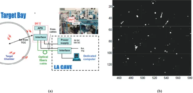
So, we first evaluate the vulnerability of such sensors to the pulsed and mixed environment associated with OMEGA laser experiments. The one million pixels tested device was located at around 4 m of the DT target, outside the target chamber. For these preliminary tests, the device was operated in its rolling shutter mode, before, during and after the shot, allowing a continuous acquisition of dark images.
Our study reveals that, for these experimental conditions, the tested APS remains fully functional after several laser shots without any degradation of its characteristics as its dark current non uniformity that is known to be affected at larger neutron fluence [7]. However, the 14 MeV neutron pulse induces a degradation of the sole image acquired during the shot, with an inhomogeneous distribution of white pixels inside the matrix (fig. 6).
(a) (b)
Figure 6.Vulnerability of a CMOS detector at OMEGA facility. (a) Experimental setup at OMEGA facility. (b) Inhomogeneous distribution of white pixels.
To allow the acquisition of the X-ray image without this perturbation, we evaluated the pertinence of a new experimental scheme that is based on the acquisition of a decaying scintillator image after the shot. One way to realize such a strategy consists in resetting the charges generated by the incoming particles and then shortly starts to record a second image, free of impacted pixels. Such scheme, based on the use of a custom Global Reset functionality, is illustrated in Fig.7.
Figure 7. Radiation hardening technique for Active Pixel Sensor.
Thanks to the Global Reset mode, the time necessary to eliminate the radiation-induced charges in the pixel is strongly decreased compared to the acquisition and removing times of one image taken with a CCD image sensor. The acquisition time should be adapted to integrate all the remaining phosphorescence for the slow scintillator that will be chosen to ensure that most of the X-ray signal will be contained in the useful image.
4. CONCLUSION
The effects of neutron-induced background on imaging systems are described for inertial confinement fusion (ICF) facilities. A compromise between optical performance and robustness has still to be found: Experimental studies and Monte-Carlo simulations are in progress to maximize the core X-ray emission sensitivity and minimize neutron and gamma ray sensitivity of each part of the plasma diagnostic. The association of adequate shielding box and innovative detection designs would allow image recording in an increasing neutron background up to at least 1016.
ACKNOWLEDGEMENTS
The authors are very grateful to all the staff, operators, and technicians of the OMEGA facility during the high neutron yield campaigns performed over these past years. The work performed by LLE personnel was supported by the U.S. DOE Office of Inertial Confinement Fusion under Cooperative Agreement No. DE-FC52-08NA28302, the University of Rochester, and the New York state Energy Research and Development Authority. The support of DOE does not constitute an endorsement by DOE of the views expressed in this article.
REFERENCES
1. Cavailler, C. et al., "Inertial fusion with the LMJ," Plasma Phys. Control. Fusion 47, B389-B403 (2005).
2. Bourgade, J. L. et al., "New constraints for plasma diagnostics development to harsh environments of MJ class lasers," Rev. Sci. Instrum. 75, 4204-4212 (2004).
3. Hamel. M. et al., "Preparation and characterization of highly lead-loaded red plastic scintillators under low energy x-rays," Nucl. Instrum. Methods. Phys. Res. A 660, 57-63 (2011).
4. Turk, G. et al., "Development of an X-ray imaging system for Laser MegaJoule," Rev. Sci. Instrum. 81, 10E509 (2010).
5. Girard, S. et al., "Vulnerability analysis of optical fibers for Laser MegaJoule facility: preliminary studies," IEEE Transactions on Nuclear Science 52, 1497-1503 (2005).
Radiation pulse
Radiation to light converter (long persistence)
USEFUL IMAGE
GLOBAL RESET
Time (A. U.)
6. Hagmann, C. et al., "Radiation induced noise in x-ray imagers for high-yield inertial confinement fusion experiments," Proc. of SPIE 8144, 814408 (2011).
7. Virmontois, C. et al., "Displacement Damage Effects Due to Neutron and Proton Irradiation on CMOS Image Sensors Manufactured in Deep Submicron Technology," IEEE Transaction on Nuclear Science 57, 3101-3108 (2010).