HAL Id: inria-00492870
https://hal.inria.fr/inria-00492870
Submitted on 17 Jun 2010
HAL is a multi-disciplinary open access
archive for the deposit and dissemination of
sci-entific research documents, whether they are
pub-lished or not. The documents may come from
teaching and research institutions in France or
abroad, or from public or private research centers.
L’archive ouverte pluridisciplinaire HAL, est
destinée au dépôt et à la diffusion de documents
scientifiques de niveau recherche, publiés ou non,
émanant des établissements d’enseignement et de
recherche français ou étrangers, des laboratoires
publics ou privés.
Anissa Lamani, Alain Cournier, Swan Dubois, Franck Petit, Vincent Villain
To cite this version:
Anissa Lamani, Alain Cournier, Swan Dubois, Franck Petit, Vincent Villain. Snap-Stabilizing Linear
Message Forwarding. [Technical Report] 2010. �inria-00492870�
Alain Cournier1, Swan Dubois2, Anissa Lamani1, Franck Petit2, and Vincent
Villain1
1
MIS, Universit´e of Picardie Jules Verne, France
2
LiP6/CNRS/INRIA-REGAL, Universit´e Pierre et Marie Curie - Paris 6, France
Abstract. In this paper, we present the first snap-stabilizing message forwarding protocol that uses a number of buffers per node being inde-pendent of any global parameter, that is 4 buffers per link. The protocol works on a linear chain of nodes, that is possibly an overlay on a large-scale and dynamic system, e.g., Peer-to-Peer systems, Grids. . . Provided that the topology remains a linear chain and that nodes join and leave “neatly”, the protocol tolerates topology changes. We expect that this protocol will be the base to get similar results on more general topologies. Key words: Dynamicity, Message Forwarding, Peer-to-Peer, Scalabil-ity, Snap-stabilization
1
Introduction
These last few years have seen the development of large-scale distributed sys-tems. Peer-to-peer (P2P) architectures belong to this category. They usually offer computational services or storage facilities. Two of the most challenging issues in the development of such large-scale distributed systems are to come up with scalability and dynamicity. Scalability is achieved by designing protocols with performances growing sub-linearly with the number of nodes (or, proces-sors, participants). Dynamicity refers to distributed systems in which topological changes can occur, i.e., nodes may join or leave the system.
Self-stabilization [1] is a general technique to design distributed systems that can tolerate arbitrary transient faults. Self-stabilization is also well-known to be suitable for dynamic systems. This is particularly relevant whenever the dis-tributed (self-stabilizing) protocol does not require any global parameters, like the number of nodes (n) or the diameter (D) of the network. With such a self-stabilizing protocol, it is not required to change global parameters in the program (n, D, etc) when nodes join or leave the system. Note that this property is also very desirable to achieve scalability.
The end-to-end communication problem consists in delivery in finite time across the network of a sequence of data items generated at a node called the sender, to a designated node called the receiver. This problem is generally split into the two following problems: (i) the routing problem, i.e., the determination
of the path followed by the messages to reach their destinations; (ii) the message forwarding problem that consists in the management of network resources in order to forward messages. The former problem is strongly related to the problem of spanning tree construction. Numerous self-stabilizing solutions exist for this problem, e.g., [2,3,4].
In this paper, we concentrate on the latter problem, i.e., the message for-warding problem. More precisely, it consists in the design of a protocol managing the mechanism allowing the message to move from a node to another on the path from the sender A to the receiver B. To enable such a mechanism, each node on the path from A to B has a reserved memory space called buffers. With a finite number of buffers, the message forwarding problem consists in avoiding deadlocks and livelocks (even assuming correct routing table). Self-stabilizing solutions for the message forwarding problem are proposed in [5,6]. Our goal is to provide a snap-stabilizing solution for this problem. A snap-stabilizing pro-tocol [7] guarantees that, starting from any configuration, it always behaves ac-cording to its specification, i.e., it is a self-stabilizing algorithm which is opti-mal in terms of stabilization time since it stabilizes in 0 steps. Considering the message-forwarding problem, combined with a self-stabilizing routing protocol, snap-stabilization brings the desirable property that every message sent by the sender is delivered in finite time to the receiver. By contrast, any self-stabilizing (but not snap-stabilizing) solution for this problem ensures the same property, “eventually”.
The problem of minimizing the number of required buffers on each node is a crucial issue for both dynamicity and scalability. The first snap-stabilizing solution for this problem can be found in [8]. Using n buffers per node, this solution is not suitable for large-scale system. The number of buffers is reduced to D in [9], which improves the scalability aspect. However, it works by reserving the entire sequence of buffers leading from the sender to the receiver. Furthermore, to tolerate dynamicity, each time a topology change occurs in the system, both of them would have to rebuild required data structures, maybe on the cost of loosing the snap-stabilisation property.
In this paper, we present a snap-stabilizing message forwarding protocol that uses a number of buffers per node being independent of any global parameter, that is 4 buffers per link. The protocol works on a linear chain of nodes, that is possibly an overlay on a large-scale and dynamic system e.g., Peer-to-Peer systems, Grids. . . Provided that (i) the topology remains a linear chain and (ii) that nodes join and leave “neatly”, the protocol tolerates topology changes. By “neatly”, we mean that when a node leaves the system, it makes sure that the messages it has to send are transmitted, i.e., all its buffers are free. We expect that this protocol will be the base to get similar results on more general topologies.
The paper is structured as follow: In Section 2, we define our model and some useful terms that are used afterwards. In Section 3, we first give an informal overview of our algorithm, followed by its formal description. In Section 4, we
prove the correctness of our algorithm. Dynamicity is discussed in Section 5. We conclude the paper in Section 6.
2
Model and definitions
Network. We consider a network as an undirected connected graph G = (V, E) where V is the set of nodes (processors) and E is the set of bidirectional com-munication links. A link (p, q) exists if and only if the two processors p and q are neighbours. Note that, every processor is able to distinguish all its links. To simplify the presentation we refer to the link (p, q) by the label q in the code of p. In our case we consider that the network is a chain of n processors.
Computational model. We consider in our work the classical local shared memory model introduced by Dijkstra [10] known as the state model. In this model communications between neighbours are modelled by direct reading of variables instead of exchange of messages. The program of every processor con-sists in a set of shared variables (henceforth referred to as variable) and a finite number of actions. Each processor can write in its own variables and read its own variables and those of its neighbours. Each action is constituted as follow:
< Label >::< Guard > → < Statement >
The guard of an action is a boolean expression involving the variables of p and its neighbours. The statement is an action which updates one or more variables of p. Note that an action can be executed only if its guard is true. Each execution is decomposed into steps.
The state of a processor is defined by the value of its variables. The state of a system is the product of the states of all processors. The local state refers to the state of a processor and the global state to the state of the system.
Let y ∈ C and A an action of p (p ∈ V ). A is enabled for p in y if and only if the guard of A is satisfied by p in y. Processor p is enabled in y if and only if at least one action is enabled at p in y. Let P be a distributed protocol which is a collection of binary transition relations denoted by →, on C. An execution of a protocol P is a maximal sequence of configurations e = y0y1...yiyi+1. . . such that, ∀ i ≥ 0, yi → yi+1 (called a step) if yi+1 exists,
else yi is a terminal configuration. Maximality means that the sequence is either
finite (and no action of P is enabled in the terminal configuration) or infinite. All executions considered here are assumed to be maximal. ξ is the set of all executions of P . Each step consists on two sequential phases atomically executed: (i) Every processor evaluates its guard; (ii) One or more enabled processors execute its enabled actions. When the two phases are done, the next step begins. This execution model is known as the distributed daemon [11]. We assume that the daemon is weakly fair, meaning that if a processor p is continuously enabled, then p will be eventually chosen by the daemon to execute an action.
In this paper, we use a composition of protocols. We assume that the above statement (ii) is applicable to every protocol. In other words, each time an enabled processor p is selected by the daemon, p executes the enabled actions of every protocol.
Snap-Stabilization. Let Γ be a task, and SΓ a specification of Γ . A protocol
P is snap-stabilizing for SΓ if and only if ∀Γ ∈ ξ, Γ satisfies SΓ.
Message Forwarding Problem. The message forwarding problem is specified as follows:
Specification 1 (SP ) A protocol P satisfies SP if and only if the following two requirements are satisfied in every execution of P :
1. Any message can be generated in a finite time;
2. Any valid message is delivered to its destination once and only once in a finite time.
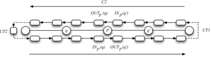
Buffer Graph In order to conceive our snap stabilizing algorithm we will use a structure called Buffer Graph introduced in [12]. A Buffer Graph is defined as a directed graph where nodes are a subset of the buffers of the network and links are arcs connecting some pairs of buffers, indicating permitted message flow from one buffer to another one. Arcs are permitted only between buffers in the same node, or between buffers in distinct nodes which are connected by communication link.
Let us define our buffer graph (refer to Figure 1):
q P q' OUT (q)p IN (q)p OUT (q')p IN (q')p C1 C2 UT1 UT2
Fig. 1. Buffer Graph
Each processor p has four buffers, two for each link (p, q) such as q ∈ Np(except
for the processors that are at the extremity of the chain that have only two buffers, since they have only one link). Each processor has two input buffers de-noted by INp(q), INp(q′) and two output buffers denoted by OU Tp(q), OU Tp(q′)
such as q, q′ ∈ N
pand q 6= q′ (one for each neighbour). The generation of a
mes-sage is always done in the output buffer of the link (p, q) so that, according to the routing tables, q is the next processor for the message in order to reach the destination. Let us refer to nb(m, b) as the next buffer of Message m stored in b, b ∈ {INp(q) ∨ OU Tp(q)}, q ∈ Np. We have the following properties:
1. nb(m, INp(q)) = OU Tq(p)
2. nb(m, OU Tp(q) = INq(p)
3
Message Forwarding
In this section, we first give the idea of our snap stabilizing message forwarding algorithm in the informal overview, then we give the formal description followed by the correctness proofs.
3.1 Overview of the algorithm
In this section, we provide an informal description of our snap stabilizing message forwarding algorithm that tolerates the corruption of the routing tables in the initial configuration.
To ease the reading of the section, we assume that there is no message in the system whose the destination is not in the system. This restriction is not a problem as we will see in Section 5.
We assume that there is a self-stabilizing algorithm, Rtables, that calculates the routing tables and runs simultaneously to our algorithm. We assume that our algorithm has access to the routing tables via the function N extp(d) which
returns the identity of the neighbour to which p must forward the message to reach the destination d. To reach our purpose we define a buffer graph on the chain which consists of two chains, one in each direction (C1 and C2 refer to Figure 1).
The overall idea of the algorithm is as follows: When a processor wants to generate a message, it consults the routing tables to determine the next neigh-bour by which the message will transit in order to reach the destination. Note that the generation is always done in the Output buffers. Once the message is on the chain, it follows the buffer chain (according to the direction of the buffer graph) and if the messages can progress enough in the system (move) then it will either meet its destination and hence it will be consumed in a finite time or it will reach the input buffer of one of the processors that are at the extremity of the chain. In the latter case, if the processor that is at the extremity of the chain is not the destination then, that means that the message was in the wrong direction. The idea is to change the direction of the message by copying it in the output buffer of the same processor (directly (UT1) or using the extra buffer (UT2), refer to Figure 1).
Note that if the routing tables are stabilized and if all the messages are in the right direction then all the messages can move on C1 or C2 only and no deadlock happens. However, in the opposite case (the routing tables are not stabilized or some messages are in the wrong direction), deadlocks may happen if no control is introduced. For instance, suppose that in the initial configuration all the buffers, uncluding the extra buffer of U T 2, contain different messages such that no message can be consumed. It is clear that in this case no message can move and the system is deadlocked. Thus in order to solve this problem we
have to delete at least one message. However, since we want a snap stabilizing solution we cannot delete a message that has been generated. Thus we have to introduce some control mechanisms in order to avoid this situation to appear dynamically (after the first configuration). In our case we decided to use the PIF algorithm that comprises two main phases: Broadcast (Flooding phase) and Feedback (acknowledgement phase) to control and avoid deadlock situations.
Before we explain how the PIF algorithm is used, let us focus on the mes-sage progression again. A buffer is said to be free if and only if it is empty (it contains no message) or contains the same message as the input buffer before it in the buffer graph buffer. For instance, if INp(q) = OU Tq(p) then OU Tq(p) is
a free buffer. In the opposite case, a buffer is said to busy. The transmission of messages produces the filling and the cleaning of each buffer, i.e., each buffer is alternatively free and busy. This mechanism clearly induces that free slots move into the buffer graph, a free slot corresponding to a free buffer at a given instant. The moving of free slots is shown in Figure 23. Notice that the free slots move
in the opposite direction of the message progression. This is the key feature on which the PIF control is based.
P p' q
a b c d
Free Buffer
(a) The input buffer of p is free. Node pcan copy the message a.
P p' q
a a b c d
Free Buffer
(b) The output buffer of p′is free.
Node p′can copy the message b.
P p' q
a b c d
Free Buffer
(c) The input buffer of p′ is free. Node
p′can copy the message c.
P p' q
a b c c d
Free Buffer
(d) The output buffer of q is free. Node qcan copy the message d.
Fig. 2. An example showing the free slot moving.
When there is a message that is in the wrong direction in the Input buffer of the processor p0, p0 copies this message in its extra buffer releasing its Input
buffer and it initiates a PIF wave at the same time. The aim of the PIF waves is to escort the free slot that is in the input buffer of p0 in order to bring it in the
Output buffer of p0. Hence the message in the extra buffer can be copied in the
output buffer to become in the right direction. Once the PIF wave is initiated no message can be generated on this free slot, at each time the Broadcast progresses on the chain the free slot moves as well following the PIF wave (the free slot moves by transmitting messages on C1 (refer to Figure 1). In the worst case, the
3
Note that in the algorithm, the actions (b) and (c) are executed in the same step (refer to the guarded action R3).
free slot is the only one, hence by moving the output buffer of the other extremity of the chain p becomes free. Depending on the destination of the message that is in the input buffer of p, either this message is consumed or copied in the Output buffer of p. In both cases the input buffer of p contains a free slot.
In the same manner during the feedback phase, the free slot that is in the input buffer of the extremity p will progress at the same time as the feedback of the PIF wave. Note that this time the free slot moves on C2 (see Figure 1). Hence at the end of the PIF wave the output buffer that comes just after the extra buffer contains a free slot. Thus the message that is in the extra buffer can be copied in this buffer and deleted from the extra buffer. Note that since the aim of the PIF wave is to bring the free slot in the output buffer of p0then when
the PIF wave meets a processor that has a free buffer on C2 the PIF wave stops escorting the previous free slot and starts the feedback phase with this second free slot (it escorts the new free slot on C2). Thus it is not necessary to reach the other extremity of the chain.
Now, in the case where there is a message in the extra buffer of p0such as no
PIF wave is executed then we are sure that this message is an invalid message and can be deleted. In the same manner if there is a PIF wave that is executed such that at the end of the PIF wave the Output buffer of p0 is not free then
like in the previous case we are sure that the message that is in the extra buffer is invalid and thus can be deleted. Thus when all the buffers are full such as all the messages are different and cannot be consumed, then the extra buffer of p0
will be released.
Note that in the description of our algorithm, we assumed the presence of a special processor p0. This processor has an Extra buffer used to change the
direction of messages that are in the input buffer of p0however their destination
is different from p0. In addition it has the ability to initiate a PIF wave. Note also
that the other processors of the chain do not know where this special processor is. A symmetric solution can also be used (the two processors that are at the extremity of the chain execute the same algorithm) and hence both have an extra buffer and can initiate a PIF wave. The two PIF wave initiated at each extremity of the chain use different variable and are totally independent.
3.2 Formal description of the algorithm
We first define in this section the different data and variables that are used in our algorithm. Next, we present the PIF algorithm and give a formal description of the linear snap stabilizing message forwarding algorithm.
Character ’?’ in the predicates and the algorithms means any value. – Data
• n is a natural integer equal to the number of processors of the chain. • I = {0, ..., n − 1} is the set of processors’ identities of the chain. • Np is the set of identities of the neighbours of the processor p.
• (m, d, c): m contains the message by itself, i.e., the data carried from the sender to the recipient, d ∈ I is the identity of the message recipient, and c is a color number given to the message to avoid duplicated deliveries. – Variable
• In the forwarding algorithm
∗ INp(q): The input buffer of p associated to the link (p, q).
∗ OU Tp(q): The output buffer of p associated to the link (p, q).
∗ EXTp: The Extra buffer of processor p which is at the extremity of
the chain.
• In the PIF algorithm
∗ Sp = (B ∨ F ∨ C, q) refers to the state of processor p, q is a pointer
to a neighbour of p. – Input/Output
• Requestp: Boolean, allows the communication with the higher layer, it
is set at true by the application and false by the forwarding protocol. • P IF -Requestp: Boolean, allows the communication between the PIF and
the forwarding algorithm, it is set at true by the forwarding algorithm and false by the PIF algorithm.
• The variables of the PIF algorithm are the input of the forwarding algo-rithm.
– Procedure
• N extp(d): refers to the neighbour of p given by the routing table for the
destination d.
• Deliverp(m): delivers the message m to the higher layer of p.
• Choice(c): chooses a color for the message m which is different from the color of the message that are in the buffers connected to the one that will contain m. – Predicate • Consumptionp(q, m): INp(q) = (m, d, c) ∧ d = p ∧ OU Tq(p) 6= (m, d, c) • leafp(q): Sq = (B, ?) ∧ (∀ q′ ∈ Np/{q}, Sq′ 6= (B, p) ∧ (consumptionp(q) ∨ OU Tp(q′) = ǫ ∨ OU Tp(q′) = INq′(p))). • N O-P IFp: Sp= (C, N U LL) ∧ ∀q ∈ Np, Sq6= (B, ?). • init-PIF : Sp= (C, N U LL) ∧ (∀q ∈ Np, Sq = (C, N U LL)) ∧ P IF -Requestp= true. • Inter-transp(q): INp(q) = (m, d, c) ∧ d 6= p ∧ OU Tq(p) 6= INp(q) ∧ (∃q′ ∈ N p/{q}, OU Tp(q′) = ǫ ∨ OU Tp(q′) = INq′(p)). • internalp(q): p 6= p0 ∧ ¬ leafp(q). • Road-Changep(m): p = p0∧ INp(q) = (m, d, c) ∧ d 6= p ∧ EXTp= ǫ ∧ OU Tq(p) 6= INp(q).
• ∀ T Action ∈ C, B, we define T Action-initiatorp the predicate: p = p0∧
(the garde of TAction in p is enabled).
• ∀ T proc ∈ {internal, leaf } and T Action ∈ {B, F }, T -Action-T procp(q)
is defined by the predicate: T procp(q) is true ∧ TAction of p is enabled.
• P IF -Synchrop(q): (Bq-internalp ∨ Fq-leafp ∨ Fq-internalp) ∧ Sq =
– We define a fair pointer that chooses the actions that will be performed on the output buffer of a processor p. (Generation of a message or an internal transmission).
Algorithm 1 PIF
– For the initiator (p0)
• B-Action:: init-PIF → Sp:= (B, −1), P IF -Requestp:= f alse.
• C-Action:: Sp= (B, −1) ∧ ∀q ∈ Np, Sq= (F, ?) → Sp:= (C, N ULL).
– For the leaf processors: leafp(q) = true ∨ |Np| = 1
• F-Action:: Sp= (C, N ULL) → Sp:= (F, q).
• C-Action:: Sp= (F, ?) ∧ ∀q ∈ Np, Sq= (F ∨ C, ?) → Sp:= (C, N ULL).
– For the processors
• B-Action:: ∃!q ∈ Np, Sq = (B, ?) ∧ Sp = (C, ?) ∧ ∀q′ ∈ Np/{q}, Sq′ = (C, ?) →
Sp:= (B, q).
• F-Action:: Sp= (B, q) ∧ Sq= (B, ?) ∧ ∀q′∈ Np/{q}, Sq′= (F, ?) → Sp:= (F, q).
• C-Action:: Sp= (F, ?) ∧ ∀q′∈ Np, Sq′= (F ∨ C, ?) → Sp:= (C, N ULL).
– Correction (For any processor)
• Sp= (B, q) ∧ Sq= (F ∨ C, ?) → Sp:= (C, N ULL).
• leafp(q) ∧ Sp= (B, q) → Sp:= (F, q).
4
Proof of Correctness
In this section, we prove the correctness of our algorithm. We first show that starting from an arbitrary configuration, our protocol is deadlock free. Next, we show that no node can be starved of generating a new message. Next, we show the snap-stabilizing property of our solution by showing that, starting from any arbitrary configuration and even if the routing tables are not stabilized, every valid message is delivered to its destination once and only once in a finite time.
Let us first state the following lemma:
Lemma 1 The PIF protocol (Algorithm 1) is snap-stabilizing.
Proof. Note that the PIF algorithm introduced here is similar to the one
proposed in [7] which is a snap stabilizing algorithm. The new thing is that we introduced the idea of dynamic leafs, processors that satisfy some properties and act like a physical leaf (they execute the F-action once they have a neighbor in a broadcast phase). Hence instead of reaching all the nodes of the chain, the PIF wave stops advancing when it meets a dynamic leaf. Note that once an internal processor p executes the B-Action, it cannot execute the F-Action unless is has a neighbor q such as Sq = (F, p) (it cannot become a leaf) since to execute the
F-action by any processor p, Sp= (C, N U LL) or for the internal processor that
executes the B-Action Sp = (B, q) (q ∈ Np, Sq = (B, p′)). Thus no processor
Algorithm 2 Message Forwarding
– Message generation (For every processor)
R1:: Requestp ∧ N extp(d) = q ∧ [OUTp(q) = ǫ ∨ OUTp(q) = INq(p)] ∧ N O-P IFp →
OUTp(q) := (m, d, choice(c)), Requestp:= f alse.
– Message consumption (For every processor)
R2:: ∃q ∈ Np,∃m ∈ M; Consumptionp(q, m) → deliverp(m), INp(q) := OUTq(p).
– Internal transmission (For processors having 2 neighbors)
R3:: ∃q ∈ Np, ∃m ∈ M, ∃d ∈ I; Inter-transp(q, m, d) ∧ (N O-P IFp∨ P IF -Synchrop(q)) →
OUTp(q′) := (m, d, choice(c)), INp(q) := OUTq(p).
– Message transmission from q to p (For processors having 2 neighbors)
R4:: INp(q) = ǫ ∧ OUTq(p) 6= ǫ ∧ (N O-P IFp∨ P IF -Synchrop(q)) → INp(q) := OUTq(p).
– Erasing a message after its transmission (For processors having 2 neighbors) R5:: ∃q ∈ Np, OUTp(q) = INq(p) ∧ (∀q′ ∈ Np \ {q}, INp(q′) = ǫ) ∧
(N O-P IFp∨ P IF -Synchrop(q)) → OUTp(q) := ǫ, INp(q′) := OUTq′(p).
– Erasing a message after its transmission (For the extremities)
R5’:: Np = {q} ∧ OUTp(q) = INq(p) ∧ INp(q) = ǫ ∧ ((p = p0) ⇒ (EXTp = ǫ)) ∧
(N O-P IFp∨ P IF -Synchrop(q)) → OUTp(q) := ǫ, INp(q) := OUTq(p).
– Road change (For the extremities)
• R6:: Road-Changep(m) ∧ [OUTp(q) = ǫ ∨ OUTp(q) = INq(p)] → OUTp(q) :=
(m, d, choice(c)), INp(q) := OUTq(p).
• R7:: Road-Changep(m) ∧ OUTp(q) 6= ǫ ∧ P IF -Requestp= f alse → P IF -Requestp:=
true.
• R8:: Road-Changep(m) ∧ OUTp(q) 6= ǫ ∧ P IF -Requestp∧ B-initiator → EXTp:=
INp(q), INp(q) := OUTq(p).
• R9:: p = p0 ∧ EXTp 6= ǫ ∧ [OUTp(q) = ǫ ∨ OUTp(q) = INq(p)] ∧ C-Initiator →
OUTp(q) := EXTp, EXTp:= ǫ.
• R10:: p = p0 ∧ EXTp 6= ǫ ∧ OUTp(q) 6= ǫ ∧ OUTp(q) 6= INq(p) ∧ C-Initiator →
EXTp:= ǫ.
• R11:: |Np| = 1 ∧ p 6= 0 ∧ INp(q) = (m, d, c) ∧ d 6= p ∧ OUTp(q) = ǫ ∧ OUTq(p) 6= INp(q)
→ OUTp(q) := (m, d, choice(c)), INp(q) := OUTq(p).
– Correction (For p0)
• R12:: p = p0∧ EXTp6= ǫ ∧ Sp6= (B, −1) → EXTp= ǫ.
• R13:: p = p0∧ Sp= (B, ?) ∧ P IF -Request = true → P IF -Request = f alse.
• R14:: p = p0 ∧ Sp= (C, ?) ∧ P IF -Request = true ∧ [(INp(q) = (m, d, c) ∧ d = p) ∨
INp(q) = ǫ] → P IF -Request = f alse.
same PIF wave. In another hand, note that the variable PIF-Request is a shared variable between the PIF algorithm and the forwarding algorithm, its role is to give the signal to the initiator to initiate the PIF wave. Hence we can deduct by analogy that the PIF algorithm proposed here is a snap stabilizing algorithm. 2 We now show (Lemma 2) that the extra buffer located at p0 cannot be
infinitely continuously busy. As explained in Section 3, this solves the problem of deadlocks.
Lemma 2 If the extra buffer of the processor p0 (EXTp0) which is at the
ex-tremity of the chain contains a message then this buffer becomes free after a finite time.
Proof. We know from Lemma 1 that each time p0 launches a PIF wave,
1. Sp = (C, N U LL). In this case R12 is enabled on p. Since the daemon is
weakly fair we are sure that R12 will be executed in a finite time. Thus EXTp will be free in a finite time too.
2. Sp = (B, ?). In this case, a PIF wave is executed on the chain. Note that
p is the initiator (it is eventually considered as the initiator). According to Lemma 1 the PIF is a Snap stabilizing algorithm. Hence, there will be a time when Sq = (F, p), q ∈ Np. Two sub cases are possible:
– Either OU Tp(q) = ǫ or OU Tp(q) = INq(p). In this case R9 is enabled
on p. Since the daemon is weakly fair, this rule will be executed in a finite time. Hence the message that is in the extra buffer will be copied in OU Tp(q) and deleted from EXTp(see Rule R9). Hence EXTp= ǫ.
– OU Tp(q) 6= ǫ and OU Tp(q) 6= INq(p). Since R10 is enabled on p and the
daemon is weakly fair, R10 will be executed in a finite time. Thus, the message that is in the extra buffer is deleted.
From the cases above, we deduct that in the case where the extra buffer of p contains a message, then this message will be either deleted or copied in OU Tp(q). Hence EXTp will be free in a finite time and the lemma holds. 2
We deduce from Lemma 2 that if the routing tables are not stabilized and if there is a message locking the Input buffer of p0, then this message is eventually
copied in the extra buffer. Since the latter is infinitely often empty (Lemma 2 again).
From now on, we suppose that no generated message is deleted (we prove this property latter).
Lemma 3 All the messages progress in the system even if the routing tables are not stabilized.
Proof. Note that if ∃q ∈ Np, INp(q) is free then if there is a message
in OU Tq(p), then this message is automatically copied in INp(q). Hence it is
sufficient to prove that the input buffer are free in a finite time. Thus Let’s prove that ∀p ∈ I, when there is a message in INp(q), this message is deleted
from INp(q) in a finite time (q ∈ Np).
Note that the input-buffers are all at an even distance from the input buffer of the processor p0. Let define δ as the distance between the input buffer of the
processor p and the input buffer of processor p0 (In the direction of the buffer
graph taken in account U T 1). The lemma is proved by induction on δ. We define for this purpose the following predicate Pδ:
If there is a message mh in INp(q) such as INp(q) is at distance δ from the
input buffer of p0 then one of these two cases happens:
– m is consumed and hence delivered to its destination.
– m is deleted from the input buffer and copied either in EXTp or OU Tp(q′)
Initialization. Let’s prove the result for P0. Suppose that there is a message
m in INp(q) such as p = p0and q ∈ Np. Two cases are possible according to the
destination (d) of m:
– d = p. In this case, since the daemon is weakly fair and since R2 keep being enabled on p then R2 will be executed on p in a finite time and the message m in INp(q) is consumed. Thus P0 is true.
– d 6= p. Since the daemon is weakly fair we are sure that p will be activated. Two cases are possible:
• OU Tp(q) = ǫ or OU Tp(q) = INq(p). In this case R6 is enabled on p.
Hence the message m is copied in OU Tp(q) and deleted from INp(q)
since a new value overwrite it (see R6). Thus P0 is true.
• OU Tp(q) 6= ǫ and OU Tp(q) 6= INq(p). According to Lemma 2, EXTp
will be free in a finite time. In another hand since the PIF is a snap stabilizing algorithm (refer to Lemma 1, we are sure that the B-Action of the initiator will be enabled on p in a finite time). Hence the message m will be copied in this case in EXTp and deleted from INp(q) (Note
that in the case where P IF -Reaquest = f alse then it is set at true (see rule R7)). Thus P0 is true.
In both cases either the message is consumed or it is removed from INp(q).
Thus P0 is true.
Induction. let δ ≥ 1. We assume that P2δis true and we prove that P2δ+2is
true as well (Recall that the input buffers are at an even distance from the input buffer of p0). Let INq(p) be the buffer at distance 2δ from the input buffer of p0
and INp(q′) the one that is at distance 2δ + 2 and contains the message m′.
In the case where the destination of m′ is p then it will be consumed in a
finite time (the daemon is weakly fair and R2 keep being enabled on p. Thus p will execute R2 in a finite time). Hence P2δ+2 is true. In the other case (the
destination of m′ is different from p), since P
2δ is true then if there is a message
m in INq(p) then we are sure that this message will be either consumed or copied
in OU Tq(q′′). Thus INq(p) = OU Tp(q) (OU Tp(q) is free). Two cases are possible
according to the rule that is executed on OU Tp(q) (depending on the value of
the pointer on OU Tp(q)) :
1. p executes R3. In this case the message m′ is copied in OU T
p(q) and deleted
from INp(q′) since a new value overwrite it (refer to Rule R3). Hence P2δ+2
is true.
2. p executes R2 (it generates a message). Hence OU Tp(q) = m′′ (m′′ is the
message generated by p). However, since P2δ is true, then the message in
INq(p) will be deleted from the buffer (q performs either an internal
trans-mission or consume the message). Hence INq(p) = OU Tp(q) in a finite time.
Nevertheless, since p generated a message in the previous step, we are sure that it will execute R3 (since the pointer on the output buffer OU Tp(q) is
From the proof above, we deduct that all the messages in the chain progress in the system and no deadlock happens even if the routing tables are corrupted. 2 Let us call a valid PIF wave every P IF wave that is initiated by the processor p0at the same time as executing R8.
Lemma 4 For every valid P IF wave, when the C-Action is executed in the
initiator either OU Tp(q) = INq(p) or OU Tp(q) = ǫ.
Proof. The idea of the proof is as follows:
– We prove first that during the broadcast phase there is a synchrony between the PIF and the forwarding algorithm. Note that when the message that was in the input buffer of the initiator is copied in the extra buffer, the input buffer becomes free. The free slot in that buffer progresses in the chain at the same time as the broadcast of the PIF wave.
– Once the PIF reaches a leaf, a new buffer becomes free in C2 (refer to Figure 1).
– As in the broadcast phase, there is a synchrony between the PIF and the forwarding algorithm during the feedback phase. (The feedback will escort the new free slot on C2 to the output buffer of p0.)
Let’s prove that during the broadcast phase there is a synchrony between the PIF and the forwarding algorithms. Let’s define for this purpose λ the distance between the processor p and the processor p0. We’re going to prove the result
by induction on λ. let’s define fot this purpose the predicate Pλ as follow:
When the PIF wave is initiated and for each extra processor p (¬leaf ∧p 6= p0)
that executes the B-action we have: ∃! q ∈ Np, Sq = (B, ?), Sp = (B, q) ∧
INp(q′) = OU Tq′(p) ∧ Sq′ = (C, N U LL) (q′∈ Np/{q}).
Initialization. Let’s prove that P1 is true. Since the PIF wave is valid,
when the PIF wave was initiated, R8 was executed at the same time. Hence, the message that was in INp0(q) was copied in EXTp0, INp0(q) = OU Tq(p0),
Sp0 = (B, −1) and Sq = (C, N U LL). Since q is not a leaf only R3 or R5 and
possibly R2 are enabled on q. Note that after the execution of one of these rules INq(q′) = OU Tq′(q) (q′∈ Nq/{p0}). In another hand R3 and R5 are not enabled
only if the B-action of the internal processor is enabled as well. Thus when the B-Action is executed (we are sure that this will happen since the PIF algorithm is snap stabilizing and the daemon is weakly fair) either R3 or R5 (possibly R2) are executed at the same time (Recall that when two actions from the PIF and the forwarding algorithm are enabled on the same processor at the same time they are both executed). Hence INq(q′) = OU Tq′(q), Sq = (B, p0) and
Sq′ = (C, N U LL). Thus P1is true. Note that if R2 is executed alone before the
B-Action then either R3 or R5 are still enabled on q. Hence when the B-Action is executed one of these two actions are executed as well.
Induction. Let λ ≥ 2. We assume that Pλ is true and we prove that Pλ+1
is true as well. Let q and p be the processors that are at distance λ and λ + 1 respectively from the processor p0. Since Pλ is true, when the B-Action of the
internal processor is executed on q, Sq = (B, q′′), INq(p) = OU Tp(q) and Sp=
(C, N U LL). In the same manner as the proof of P1, R3 or R5 and possibly R2
is enabled on p. Note that R3 or R5 keep being enabled unless they are executed (Note that R1 cannot be executed since there is a PIF wave that is executed in the neighbourhood. Thus no message is generated). In another hand R3 and R5 cannot be executed unless the B-Action is enabled as well. Hence when the B-Action is executed either R3 or R5 or R2 is executed at the same time. Hence INp(q′) = OU Tq′(p), Sp= (B, q) and Sq′ = (C, N U LL). Thus Pλ+1 is true.
We can deduct that for the last processor p that is an internal processor (p 6= p0 and ¬ leaf), Sq = (B, q′′) and INp(q′) = OU Tq′(p), Sp = (B, q) and
Sq′ = (C, N U LL). Since p is the last processor which is an internal processor
then q′ is a leaf. Two cases are possible:
– The leaf is the processor q′ that is at the extremity of the chain such as
q′ 6= p
0. Either R2 or R11 are enabled on q′. Note that the F-Action is
enabled as well since q′ is a leaf and S
p = (B, ?). When one of these two
rules is executed with the F-Action, Sq′ = (F, p) and INq′(p) = OU Tp(q′).
– The leaf q′ is not the processor that is at the border of the chain. In this
case either R2 or R3 or R4 are enabled. Recall that the F-action is enabled as well. Then once the F-Action of the internal processor and one of these rules are executed, Sq′ = (F, p) and INq′(p) = OU Tp(q′).
Note that in both cases, once the leaf q′ executed the F-Action we have the
following property: Sq′ = (F, p) and INq′(p) = OU Tp(q′). Now in the same
manner that we proved the synchrony between the PIF and the forwarding algorithm during the broadcast phase. We prove the synchrony between these two algorithms during the feedback phase. The proof is by induction on λ using the following predicate: For every internal processor p that executes the F-Action, Sp= F, q, Sq′ = (F, p), Sq′ = (B, ?) and INp(q) = OU Tq(p) (q, q′∈ Np, q 6= q′).
Then when the last internal processor executes that F-action (note that the last processor is the one that is neighbour to the initiator) these properties are verified. Hence the Output buffer of the initiator is becomes free and the lemma holds.
2 In the remainder, we say that a message is in a suitable buffer if the buffer is on the right direction to its destination. A message is said to be deleted if it is removed from the system without being delivered.
Let m be a message. According to Lemma 3, m progresses in the system (no deadlock happens and no message stays in the same buffer indefinitely). So, if m is in a buffer that is not suitable for it, then m progresses in the system according to the buffer graph. Thus, it eventually reaches an extremity, which changes its direction. Now, m is ensured to reach its destination, leading to the following lemma:
Lemma 5 For every message that is not in a suitable buffer, it will undergo exactly a single route change.
Proof. Let m be a message. According to Lemma 3, m progresses in the
system (no deadlock happens and no message stays in the same buffer indefi-nitely). So, if m is not in a buffer that is not suitable for it, then m progresses in the system according to the buffer graph. Two cases are possible:
– m will be in a finite time in the Input buffer of the processor p0. Since the
message is in a buffer that is not suitable for it, p0 is not the destination
of m. However we are sure that EXTp will be free in a finite time (refer
to Lemma 2) and that the B-Action will be enabled on p0 in a finite time
too (The PIF is a snap stabilizing algorithm). Hence the message in INp0(q)
will be copied in EXTp0 and a PIF wave is initiated at the same time. In
another hand, it has been shown in Lemma 4 that in the case of a valid PIF wave (Note that this is our case) when the PIF ends (Sq = (F, p0)) and
C-Initiator is enabled on p0(we are sure that this will happen since the PIF
is snap stabilizing) and OU Tp(q) becomes free. Hence R9 is enabled on p0
and the message that is in the extra buffer can be put in the output buffer of p0 and deleted from the extra buffer. Note that since the network is a
chain and p0is at the extremity of this chain, we are sure that the message
will meet its destination since it can visit all the processors. Hence no other changes route are done.
– The message will reach the input buffer of the processor p′ that is at the
other extremity of the chain (p′ 6= 0). Since the messages progress in the
system (see Lemma 3) OU Tp′(q′) will be free in a finite time. Hence when
a message that is not intended to q is in INq(q′) and since the daemon is
weakly fair, we are sure that q will execute R11 in a finite time. Thus the message will be copied in OU Tq(q′) and deleted from INq(q′). Now since q
is at the extremity of the chain, the message will meet its destination hence no other route change is performed and the lemma holds.
2 Once the routing tables are stabilized, every new message is generated in a suitable buffer. So, it is clear from Lemma 5 that the number of messages that are not in a suitable buffer strictly decreases. The next lemma follows:
Lemma 6 When the routing tables are stabilized and after a finite time, all the messages are in buffers that are suitable for them.
Proof. When the routing table are stabilized some of the messages still are
in buffers that are not suitable for then. However, since the routing tables are stabilized, every message is generated in a suitable buffer, hence the number of messages that are in buffers that are not suitable for them does not increase. In another hand, According to Lemma 5, every message that is in the wrong direction will undergo exactly one route change and hence all the wrong messages
that are in the system will be in the right direction in a finite time and the lemma holds.
2 From there, it is important to show that any processor can generate a message in a finite time. From Lemma 6, all the messages are in suitable buffers in a finite time. Since the PIF waves are used for route changes only, then no PIF wave will be initiated. That what we show in the two following lemmas:
Lemma 7 In the case where PIF-Request=true, it will be set at false in a finite time.
Proof. Note that in the case where PIF-request is true and the B-Action
of the initiator is enabled on p0, PIF-Request will be set at false when the
B-Action is executed (see B-Action of the initiator). Otherwise two cases are possible according to the state of the initiator:
– Sp0 = (B, ?). In this case PIF-Request is set at false by the forwarding
algorithm by executing R13 (R13 is enabled on p0and the daemon is weakly
fair).
– Sp0 = (C, N U LL). If INp0 contains a messages and the destination of he
message is not p0then PIF-Request will be set at false by the PIF algorithm
once the PIF-wave is initiated. However in the case where the input buffer of p0 is empty or contains a message to p0then R14 is enabled and since the
daemon is weakly fair R14 will be executed on p0 and hence PIF-Request is
set at false.
From the cases above we can deduct that if PIF-Request is true then it will be
set at false in a finite time and the lemma holds. 2
Lemma 8 When the routing tables are stabilized and all the messages are in suitable buffer, no PIF wave is initiated.
Proof. According to Lemma 7. PIF-Request will be set at false in a finite
time. Note that the only rule that set PIF-Request at true is R7. However R7 is never enabled since all the messages on the chain are in suitable buffer and since the routing tables are correct (all messages are generated in suitable buffer).
Thus the lemma holds. 2
From this point, the fair pointer mechanism cannot be disrupted by the PIF waves anymore. So, the fairness of message generation guarantees the following lemma:
Lemma 9 Any message can be generated in a finite time under a weakly fair daemon.
Proof. According to Lemma 8, when the routing tables are stabilized and
and no Road-change are executed. In another hand since the routing tables are stabilized and since the buffer graph of the chain consists on two disjoint chains (it is a DAG) then no deadlock happens and all the messages progress in the system. Now suppose that the processor p wants to generate a message. Recall that the generation of a message m for the destination d is always done in the output buffer of the processor p connected to the link (p, q) such as N extp(d) = q.
Two cases are possible
1. OU Tp(q) = ǫ. In this case, the processor executes either R1 or R3 in a finite
time. the result of this execution depends on the value of the pointer. Two cases are possible:
– the pointer refers to R1. Then p executes R1 in a finite time and we obtain the result.
– the pointer refers to R3. Then p executes R3 in a finite time. Hence OU Tp(q) 6= ǫ and we retrieve case 2. Note that the fairness of the
pointer guarantees us that this case cannot appear infinitely.
2. OU Tp(q) 6= ǫ. Since all the messages move gradually in the buffer graph we
are sure that OU Tp(q) will be free in a finite time and we retrieve case 1.
We can deduct that every processor can generate a message in a finite time. 2 Due to the color management (Function Choice(c)), the next lemma follows: Lemma 10 The forwarding protocol never duplicates a valid message even if A runs simultaneously.
Proof. Three cases are possible:
– m is in INp(q). According to the rules that are enabled on p, three cases are
possible
• the message is consumed (R2 is executed ) hence the message m is deleted from INp(q) since a new value overwrites since INp(q) = OU T q(p) (Note
that this happen only when OU Tq(p) 6= INp(q)).
• R8 is executed . The message is copied in EXTp (for the processor
p0) and deleted from INp(q) since a new value overwrites (INp(q) =
OU T q(p)) in a sequential manner.
• R4 is executed. The message is put in this case in OU Tp(q′) and deleted
from INp(q) in a sequential manner hence only one copy is kept (q′ ∈
Np/{q}). Note that these two rules are not enabled only if OU Tq(p) does
not contain the same message.
– m is in OU Tp(q). In this case the message m is copied in the input buffer of
the processor q (INq(p)). Hence two copies are in the system. However the
message in INq(p) is not consumed and not transmitted unless the copy in
– m is in EXTp. In this case the message is either deleted or put in OU Tp(q).
Since this operation is a local operation (the copy is done between two buffer of the same processor) then the message is copied in the new buffer and deleted from the previous one in a sequential manner.
From the cases above we can deduct that no message is duplicated in the
system. Hence m is delivered at most once to its destination. 2
From Lemma 9, any message can be generated in a finite time. From the PIF mechanism and its synchronization with the forwarding protocol the only message that can be deleted is the message that was in the extra buffer at the initial configuration. Thus:
Lemma 11 Every valid message (that is generated by a processor) is never deleted unless it is delivered to its destination even if Rtables runs simulta-neously.
Proof. The proof is by contradiction, suppose that there is a message m
that is deleted without being delivered to its destination.
By construction of R3, this cannot be a result of an internal forwarding since the message m is first of all copied in the Output-buffer OU Tp(q) and then erased
from the Input-buffer INp(q′) since a new value overwrites it. Note that these
two rules are enabled only if OU Tp(q)=INq(p) or OU Tp(q) = ǫ. Hence when the
message m is copied in the OU Tp(q) no message is deleted (one copy remains in
INq(p) in the case where INq(p) = OU Tp(q)).
By the construction of Rule R4, the message is only copied in the Input-Buffer and not deleted from the Output-buffer at the neighbour processor simultane-ously (the only rules that delete a message from the Output-buffer are R5 and R3 and the guards of these rules are not verified when R4 is enabled).
If R5 is enabled in processes p, that means that OU Tq(p) = INp(q) and
INp(q′) = ǫ, q′ ∈ Np/{q}. When one of these two rules are enabled, OU Tp(q) = ǫ.
However according to the color management (Function Choice(c)), we are sure that a copy of the message that was in OU Tp(q) is in INq(p).
By the construction of the rules R6 and R11, this cannot be the result of the execution of these two rules because the message that is in INp(q) such as
p0and p is not the destination, is copied in the Output buffer and deleted from
the Input buffer sequentially and then p copies the message that is in OU Tq(p)
in INp(q) , so no message is deleted.
Concerning R12, EXTp such as p0 contains the message m and Sp= (C, ?),
which means that no PIF is executed. However, for p0, a message in INp(q) is
copied in EXTp(in the case where p is not the destination) only if R8 is enabled,
however, when R8 is enabled B-intiator is enabled as well. Since in this case the two rules are executed at the same time, hence Sp = (B, ?). Now, for the
processor p, Since the PIF is a valid PIF, when the C-Action of p is enabled at the same time as the rules R10 or R9. If R10 is executed then EXTp = ǫ
and Sp = (C, N U LL) (since OU Tp(q) = ǫ or OU Tp(q) = INq(p)), which is a
in the extra buffer of p (EXTp) is copied in OU Tp(q), EXTpbecomes free and
Sp = (C, ?), which is a contradiction with our case. Hence we are sure that the
message that is in the extra buffer of p is a message that was not generated by a processor. Hence when R12 is executed, this message is deleted (no valid message is deleted).
By the construction of the two rules R8 and R9, No valid message is deleted by the execution of the two rules, since the message is copied in the extra buffer (R8) or in the Output buffer (R9) and then it is deleted from the Input buffer (R8) or the extra buffer (R9).
Concerning the rule R10, according to Lemma 4, when the message that is in EXTpis valid, when the C-Action of the initiator is enabled either OU Tp(q) = ǫ
or OU Tp(q) = INq(p). However no such buffers exist. Hence the message in the
extra buffer of p is not a valid message (it is not generated by a processor). Hence it can be deleted.
We can deduct from all the cases above that no message that is generated by a processor is deleted, hence the lemma holds.
2
Theorem 1. The proposed algorithm (Algorithms 1 and 2) is a snap-stabilizing message forwarding algorithm (satisfying SP) under a weakly fair daemon.
Proof. From Lemma 9, any message can be generated in a finite time.
From Lemma 11, every valid message is never deleted unless it is delivered to its destination even if Rtables runs simultaneously. From Lemma 10, no valid
message is duplicated. Hence, the theorem holds. 2
Remarque
For any processor p, Forwarding protocol delivers at most 4n−3 invalid messages.
Proof. Assume that in the initial configuration all the buffers contain a
message, since these messages were not generated by the processors of the system, they are invalid messages. Suppose that the destination of the message m in INp(q) is the processor p such as q = 0 and Sq = (B, −1). Suppose that the
daemon activates p which executes R2 and the F-action (it is a leaf) . Hence the message m is consumed and INp(q) = OU Tq(p). Hence OU Tq(p) becomes free
and the C-action of the initiator is enabled, q will copy then the message from EXTq in OU Tq(p) and will execute the C-Action. In another hand, since there
is no way to know if the messages are valid or not, they all be treated as if they are valid. Since the forwarding algorithm is snap stabilizing, all the messages that were in the buffer of the chain at the beginning are delivered. Since there is 4n-3 buffers in the system, then 4n-3 invalid messages can be delivered and the lemma holds.
5
Dynamicity
In dynamic environments, processors may leave or join the network at any time. To keep our solution snap stabilizing we assume that there are no crashes and if a processor wants to leave the network (disconnect), it releases its buffers (it sends all the messages it has to send and wait for their reception by its neighbours) and accepts no more message before leaving.
In this discussion we assume that the rebuilt network is still a chain. It is fundamental to see that in dynamic systems the problem of keeping messages for ghost destinations with the hope they will join the network again and the lack of congestion are contradictory. If there is no bound on the number of leavings and joins this problem do not admit any solution. The only way is to redefine the problem in the context of dynamicity. For example we can modify the second point of the specification (SP) as follows: A valid message m generated by the processor p to the destination q is delivered to q in a finite time if m, p and q are continuously in the same connected component during the forwarding of the message m. Even if that could appear very strong, this kind of hypothesis is often implied in practice. However we can remark that this new specification is equivalent to SP in static environments. Our algorithm can easily be adapted in order to be snap stabilizing for this new specification in dynamic chains.
Thus we can now delete some messages as follows: we suppose that every message has an additional boolean field initially set to false. When a message reaches an extremity which is not its destination we have two cases: (i) The value of the boolean is false, then the processor sets it to true and sends it in the opposite direction. (ii) The value of the boolean is true, then the processor deletes it (in this case, if the message is valid, it crossed all the processors of the chain without meeting its destination).
Finally, in order to avoid starvation of some processors, the speed of joins and leavings of the processors has to be slow enough to avoid a sequence of PIF waves that could prevent some processors to generate some messages.
6
Conclusion
In this paper, we presented the first snap-stabilizing message forwarding protocol that uses a number of buffers per node being independent of any global param-eter. Our protocol works on a linear chain and uses only 4 buffers per link. It tolerates topology changes (provided that the topology remains a linear chain). This is a preliminary version to get the same result on more general topologies. In particular, by combining a snap-stabilizing message forwarding protocol with any self-stabilizing overlay protocols (e.g., [13] for DHT or [14,15,16] for tries), we would get a solution ensuring users to get right answers by querying the overlay architecture.
References
2. Huang, S.T., Chen, N.S.: A self-stabilizing algorithm for constructing breadth-first trees. Inf. Process. Lett. 41(2) (1992) 109–117
3. Kosowski, A., Kuszner, L.: A self-stabilizing algorithm for finding a spanning tree in a polynomial number of moves. In: PPAM. (2005) 75–82
4. Johnen, C., Tixeuil, S.: Route preserving stabilization. In: Self-Stabilizing Systems. (2003) 184–198
5. Awerbuch, B., Patt-Shamir, B., Varghese, G.: Self-stabilizing end-to-end commu-nication. Journal of High Speed Networks 5(4) (1996) 365–381
6. Kushilevitz, E., Ostrovsky, R., Ros´en, A.: Log-space polynomial end-to-end com-munication. In: STOC ’95: Proceedings of the twenty-seventh annual ACM sym-posium on Theory of computing, ACM (1995) 559–568
7. Bui, A., A, D., Petit, F., Villain, V.: Snap-stabilization and PIF in tree networks. Distributed Computing 20(1) (2007) 3–19
8. Cournier, A., Dubois, S., Villain, V.: A snap-stabilizing point-to-point communi-cation protocol in message-switched networks. In: 23rd IEEE International Sym-posium on Parallel and Distributed Processing (IPDPS 2009). (2009) 1–11 9. Cournier, A., Dubois, S., Villain, V.: How to improve snap-stabilizing
point-to-point communication space complexity? In: Stabilization, Safety, and Security of Distributed Systems, 11th International Symposium (SSS 2009). Volume 5873 of Lecture Notes in Computer Science. (2009) 195–208
10. Edsger, W., Dijkstra.: Self-stabilizing systems in spite of distributed control. Com-mum. ACM 17(11) (1974) 643–644
11. Burns, J., Gouda, M., Miller, R.: On relaxing interleaving assumptions. In: Pro-ceedings of the MCC Workshop on Self-Stabilizing Systems, MCC Technical Report No. STP-379-89. (1989)
12. Merlin, P.M., Schweitzer, P.J.: Deadlock avoidance in store-and-forward networks. In: Jerusalem Conference on Information Technology. (1978) 577–581
13. Bertier, M., Bonnet, F., Kermarrec, A.M., Leroy, V., Peri, S., Raynal, M.: D2HT: the best of both worlds, Integrating RPS and DHT. In: European Dependable Computing Conference. (2010)
14. Aspnes, J., Shah, G.: Skip Graphs. In: Fourteenth Annual ACM-SIAM Symposium on Discrete Algorithms. (January 2003) 384–393
15. Caron, E., Desprez, F., Petit, F., Tedeschi, C.: Snap-stabilizing Prefix Tree for Peer-to-peer Systems. In: SSS 2007, Springer Verlag Berlin Heidelberg (2007) 82– 96
16. Caron, E., Datta, A., Petit, F., Tedeschi, C.: Self-stabilization in tree-structured p2p service discovery systems. In: 27th International Symposium on Reliable Dis-tributed Systems (SRDS 2008), IEEE (2008) 207–216