HAL Id: hal-01851423
https://hal.archives-ouvertes.fr/hal-01851423
Submitted on 25 Apr 2019HAL is a multi-disciplinary open access
archive for the deposit and dissemination of sci-entific research documents, whether they are pub-lished or not. The documents may come from teaching and research institutions in France or abroad, or from public or private research centers.
L’archive ouverte pluridisciplinaire HAL, est destinée au dépôt et à la diffusion de documents scientifiques de niveau recherche, publiés ou non, émanant des établissements d’enseignement et de recherche français ou étrangers, des laboratoires publics ou privés.
In situ thermal gradient controlled investigation of
spallation - Experimental design and preliminary results
Julien Sniezewski, Yannick Le Maoult, Philippe Lours
To cite this version:
Julien Sniezewski, Yannick Le Maoult, Philippe Lours. In situ thermal gradient controlled investi-gation of spallation - Experimental design and preliminary results. HTCPM 2008 -7th International Symposium on High Temperature Corrosion and Protection of Materials, May 2008, Les Embiez, France. p.1135-1143, �10.4028/www.scientific.net/MSF.595-598.1135�. �hal-01851423�
In Situ Thermal Gradient Controlled Investigation of Spallation
-Experimental Design and Preliminary Results
Julien Sniezewski
a, Yannick Le Maoult
b, Philippe Lours
cUniversité de Toulouse, Mines Albi
CROMeP - Research Centre on Tools, Materials & Processes Campus Jarlard, 81013 Albi cedex 9, France
ajulien.sniezewski@enstimac.fr, byannick.lemaoult@enstimac.fr, cphilippe.lours@enstimac.fr
Keywords: cyclic oxidation, thermal gradient, in situ analysis, videometry, TBC.
Abstract. Based on a coupled numerical and experimental approach, the design and implementation of an in situ thermal-gradient-controlled cyclic oxidation test, dedicated to the investigation of the TGO and TBC spallation, is presented. The influence of the specimen through thickness thermal gradient as well as the benefits of the video real-time monitoring of the cooling phase of an oxidation test is discussed in the case of the spallation of an alumina scale grown on FeCrAl alloys. Introduction
Alumina forming alloys and complex systems such as thermal barrier coatings are used in industrial applications and gaz-turbine engines where superior oxidation resistance and good thermal insulation performances are required [1,2,3]. During service cycles, at high temperature, such materials are subject to severe thermomechanical stresses. Those stresses may provoke the degradation of oxide scales or coatings through cracking or spalling and thus limit the lifetime of components. Thermal stresses result from the thermal gradient that establishes through the thickness of the multi layers systems [4,5].
Various experimental techniques are used to investigate the durability and failure mechanisms and to study the behaviour of the materials. Isothermal [6] and cyclic oxidation [7] tests, thermogravimetry analysis [8] and acoustic emission [9] are the most employed techniques. More evolved techniques are also used such as the infrared characterization [10] (thermal wave imaging) and photo-luminescence piezo-spectroscopy (PLPS) [11].
However, all those approaches suffer some limitations. Isothermal and cyclic oxidation test, thermal wave imaging and PLPS do not give insight into the dynamics of spallation events. Thermogravimetry analysis is intrinsically a global approach and acoustic emission does not permit to discriminate easily oxide scale cracking and oxide scale spallation. An additional limitation of such techniques lies in the fact that they generally omit to generate and control a thermal gradient through the thickness of the samples while tested. Previously reported studies based on an in situ approach have evidenced the strong influence of several parameters on spallation, namely the oxide layer thickness, the substrate microstructure, the characteristics of the thermal cycles. Most importantly, it was also shown that the thermal gradient through the thickness of the investigated specimens, either during heating or cooling, is of primary importance. In addition, the occurrence of such a gradient corresponds to most of the industrial situations suffered by high temperature materials. As a consequence, dedicated cyclic oxidation equipment has been designed. It is able to
generate such a gradient and is instrumented in such a way to monitor in situ the spallation events. This paper aims at describing the design and implementation of such an equipment and finally gives a few examples of the real-time analysis of the surface degradation.
Design of an in situ thermal gradient controlled cyclic oxidation test
General specifications. The objective of the present work is to design an automated cyclic oxidation test able to generate a thermal gradient within the investigated specimens and instrumented with video camera to monitor in situ the behaviour of the oxidised and/or coated surface during the cooling phases of cumulative cycles. The videometry in situ technique as well as its outstanding benefit for studying spallation has been reported in [12]. In this paper, it is pointed out that the cooling rate, imposed by the cooling media in which the sample holder is immersed and leading to the establishment of a thermal gradient within the specimen, has a strong impact on the extent of spallation and possibly the characteristic size of individual spalled particles. However, the influence of a thermal gradient can only be established if this parameter is fully controlled and measured over the whole thermal cycles imposed to the specimens. In order to couple those videometry and thermal approaches, the developed experimental means must satisfy a fourfold general technical specifications, namely:
i) It must be entirely automated. This is ensured by the implementation of a computer-aided shuttle-furnace whose motion on top and out of specimens results in the required programmed thermal cycling.
ii) It must be versatile enough to cover a large range of possible programmable thermal cycles. Indeed, the experimental mean must be able to cycle specimens, in particular thermal barrier coatings, according to the universal commonly used cycle including a 10 to 15 minutes heating from room temperature to 1100°C-1150°C (heating rate about 1.3°C.s-1), a high temperature holding time of one hour and a 20 minutes cooling (cooling rate about 1°C.s-1). In addition, in order to thoroughly investigate spallation mechanisms and the influence of the cycle characteristics, it must also be able to test specimens using more exotic cycles and/or thermal shocks. This may serve to limit or enhance surface degradation, by changing for instance the exposure temperature (up to 1400°C to test a wide range of materials), the exposure time, the heating and cooling rates (two times higher than the values given above).
iii) It must be instrumented with interchangeable cameras to monitor possible spallation events at each individual cycle. Here again, the versatility of the optical characterization allows the observation scale of specimens to be changed by changing the focal length of the camera, the resolution of the images to be increased or decreased by changing the data acquisition frequency of the digital camera (number of images per seconds). This also permits thermal information characteristic of surface degradation to be obtained by using infrared thermography camera.
iv) It must be able to impose a given thermal gradient within the specimens during both the phases of oxidation and cooling. This gradient, that can reach about 200°C through the thickness of thermal barriers coatings for instance, must be generated, controlled and measured precisely.
Thermal performances. The principle used to establish a thermal gradient within the material consists of absorbing the heat flux that occurs across the bottom surface of the specimen as its top surface is exposed to the radiation of the flat heating resistance of the furnace located 10 cm above the specimen. To guarantee this thermal condition, a specific sample holder composed of a metallic cylinder chilled by the circulation of a coolant has been designed. To validate this technical
solution, a prototype has been manufactured and tested using a 5 mm thick FeCrAl specimen. Several thermocouples have been welded on the bottom surface of the sample and at different locations along the overall height of the specimen holder. Fig. 1 shows the temperature monitoring of all those thermocouples when the specimen on top of the sample holder is inserted in an infrared furnace at 1150°C. The various temperatures of both the specimen and the sample-holder stabilize within less than 2000 seconds and the measured gradient through the thickness of the specimen is about 100°C, provided the coolant is maintained at 40°C, which unambiguously suggests that the cooling of the specimen holder is proper to generate the required thermal gradient.
However, this first approach has to be optimized in order to design the final ready-to-use specimen-holder. This specimen holder is composed of different parts, namely a superior ceramic plate with five holes in which specimens are located on top of several IN625 cylinders piled up to vary its total height. The bottom cylinder - made of stainless steel - is circulated by a coolant supplied with a large volume heat exchanger whose characteristics permit to adjust the gradient. The temperature at the bottom surface of the specimen is measured by a thermocouple that crosses the whole height of the specimen holder while the top surface temperature is controlled by a pyrometer (with wavelength in the range 8-14 µm). Fig. 2 gives the temperature measurements at the top and bottom surfaces of a specimen of AM3 superalloy (2 mm thick) coated with EB-PVD YSZ (200 µm) exposed at 1050°C within the resistance furnace together with the targeted cycle and the resulting thermal gradient within the thickness of the specimen.
Fig. 1. Temperature monitoring during thermal cycling of the prototype sample-holder and a
FeCrAl specimen.
Fig. 2. Temperature monitoring during thermal cycling of a TBC on top of the newly designed
sample-holder.
It is shown that the effective thermal cycle suffered by the specimen is extremely close to the targeted cycle in terms of heating and cooling rates and maximum temperature reached. Also, those measurements indicate that the cooled sample-holder is prone to generate a 180°C stationary thermal gradient across the investigated material.
To address the performance of the sample-holder, both transient and stationary numerical simulations were performed using Femlab software. The boundary conditions and materials properties for the calculations are given in Fig. 3. The first case investigated simulates the isothermal exposure of a 2 mm thick Hastelloy X substrate coated with 200µm thick zirconia either in bulk form or deposited with EB-PVD and plasma spray techniques. In this later case, two types of zirconia are studied, namely a high-density and a low-density material. The coated material is
located on top of a cylindrical 40 mm high stainless steel specimen-holder whose bottom surface is maintained at room temperature. The top surface of the material is exposed to 1273 K. The calculated temperatures are given in Fig. 4, showing that a stationary thermal gradient establishes both in the coating and the substrate. Depending on the nature of zirconia, the thermal gradient within the coating changes drastically from say, 90°C for the high conductivity bulk material to 150°C for the low-conductivity, low-density plasma sprayed material.
Thermal conductivity (W/m.K) Materials at: 20°C at: 1000°C Aluminium 237 Ainsi 316L 13,5 28,5 PM2000 10,9 27 Hstelloy X 10 30 Alumina 38 6 Zirconia 2,5 1,65 EB-PVD YSZ 1,7 1,45
High density APS YSZ 1,4 1 Low density APS YSZ 0,8 0,7
Fig. 3. Material thermal properties and boundary conditions used for the calculation.
A transient calculation, simulating the cooling phase of a 5 mm thick FeCrAl substrate covered with a 30 µm thermally grown alumina oxide and located on top of an aluminium sample-holder, is performed. The top surface of the bi-material is held at 1300K while the opposite extremity of the sample-holder is cooled at 278 K. Fig. 5 shows the evolution of the temperature on the top surface (oxide), at the interface between the oxide and the substrate and at the bottom surface of the substrate, against the cooling time. The calculation shows that no gradient occurs within the (too thin) oxide scale while some gradient establishes across the thickness of the substrate. This is particularly significant during the very first stages of cooling where the gradient reaches about 200°C - 400°C. After a few seconds, namely 30 seconds, the gradient gradually vanishes and the overall specimen is almost isothermal. Note that the cooling kinetics and the time-scale for lowering the gradient down to zero are much shorter than that measured experimentally. This is due to the fact that no thermal contact resistance between the various components of the model has been considered for the calculation. Indeed, it is particularly difficult to estimate such values that strongly depend on the surface finish of the materials involved.
Aluminium ξ=40mm Stainless steel Ainsi 316L ξ=40mm PM2000 ξ=5mm Hastelloy X ξ=2mm Case 1 Case 2 T1=293K T2=278K Al2O3 ξ=35µm EB-PVD YSZ ξ=200µm A di aba tic
Fig. 4. Various stationary thermal gradients in different TBC.
Fig. 5. Evolution of temperature during the cooling of an oxidised FeCrAl. Optical performances. A high resolution CCD camera is used to monitor spallation events.
The sensor is composed of a matrix with 1600 by 1200 pixels and can take 7.5 images per second in full resolution. It is also possible to increase the number of image per second if the resolution is lowered. The focal length of the camera can be varied from 28 to 200 mm, which guarantees the possibility to view either the whole surface of a 20 mm by 20 mm specimen or to observe much smaller zones to investigate fine details of spallation events. The images taken by the camera are directly recorded on a computer and can be straightforwardly treated using image analysis software. The mass resolution of the technique can be calculated from the specifications and the optical characteristics of the camera. Considering that the smallest detectable spall accurately corresponds to the size of an elementary pixel of the camera detector, the mass variation ∆m can be written as (Eq. 1) :
Table.1 Mass resolutions for various coatings Type of coatings and thickness Density ρo [g.cm-3] Mass resolutions (1) YSZ TBC, ξo = 200µm 3 0.0468µg YSZ TBC, ξo = 100µm 3 0.0234µg Alumina TGO, ξo = 30µm 3.9 0.0112µg
∆m=
d
specimend
focal
2δx δy ξ
oρ
o Alumina TGO, ξo = 15µm 3.9 0.0056µgwhere dspecimen = 400 mm is the distance from the camera to the specimen, dfocal = 200 mm is the
focal length of the camera, δx (4.4 µm) and δy (4,4 µm) are the sizes of a pixel for the camera used
in the experiments, ξo and ρo are respectively the coating thickness and density. Table 1 gives some
examples of mass resolution for various coatings. These mass resolutions are extremely high and do not correspond perfectly to the effective capability of the experimental technique. Indeed, though it is theoretically possible to detect spalled zones as small as the size of a pixel, which was used for the calculation, it is nevertheless very difficult to achieve. In practise, the reasonable smallest zone
that can be viewed is about 10 pixels, which increases by an order of magnitude the minimum detectable mass of spalled particles.
Preliminary results
In order to illustrate the capability of an in situ thermal gradient controlled cyclic oxidation test, two examples are presented in the following. The first one shows the possible insight on the mechanisms of spallation of an alumina scale thermally grown on a FeCrAl alloy allowed by the real time monitoring of a cooling sequence using a high-resolution/high-speed camera. The second example focuses on the impact of a thermal gradient through the thickness of the oxidised and cooled specimen on the characteristics of the overall spallation kinetics.
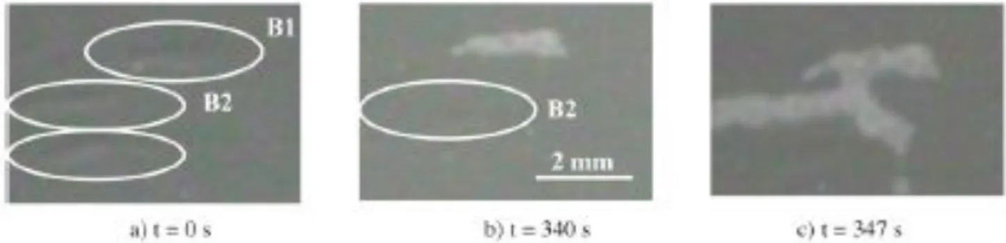
Mechanisms of spallation. It has been extensively reported in the literature that the so-called buckling mode might be the preferred spallation route for thermally grown oxide [3], However, investigation of extensively spalled specimens observed after surface degradation is fully completed, only provides global information and fails to prove unambiguously that spallation occurred through buckling. Indeed, buckling is a progressive mechanism that can be divided in various successive steps including the formation of the buckle itself, the possible, more or less protracted stabilisation of the buckle and finally the ejection of the spall. The thorough analysis of buckling requires investigating in situ the mechanism, preferentially using methods that shows directly the different steps of buckle formation and ejection. Fig. 6 shows three images extracted from a video recording of the surface of a FeCrAl alloy initially oxidised at 1300°C and cooled down to room temperature.
Fig. 6. Buckle formation and spallation monitored by high resolution camera.
The long-term oxidation of the material results in the formation of a 25µm thick alumina scale prone to spall upon cooling. The first micrograph shows the presence of three buckles giving an undulated aspect to the surface. Those buckles were formed during cooling at a temperature higher than 500°C. Buckles labelled (B1) and (B2) remain stable as no change in their morphology and size occurred during 340 seconds, the time interval separating the first and the second image (Fig. 6 a and Fig. 6 b). In Fig. 6 b, the contrast of buckle (B1) drastically changes suggesting that it detaches from the alloy substrate. At this stage, the buckle (B1) reaches its instability threshold as the thermal induced shear stress exceeds the alumina strength. Because of geometrical and morphological reasons leading to a slight different stress state, the buckle labelled (B2) remains further stable over a longer time but finally suffers the same instability after 7 seconds more (figure 6c).
As indicated, the stability phase of buckles can be quite different from one part of the specimen to another. This is also true from one specimen to another or from one condition of cooling to another.
Namely, it can strongly depend on the microstructure of the alloy substrate, in relation for instance to the crystal orientation of the grain or to the presence of a grain boundary underneath the oxide scale. It can be also influenced by the cooling rate or by the thermal gradient imposed through the thickness of the specimen.
In Fig. 7, the formation of a buckle in an alumina scale, grown at the surface of a FeCrAl alloy following 384 hours holding at 1300°C then cooled to room temperature, is shown to occur within two successive frames of the video recording. The in situ recording is performed using a high-speed camera capable of discriminating 88000 images per second. Each frame lasts 11 µs.
Fig. 7. Buckle formation and spallation monitored by a high-speed camera.
Unfortunately, the high-speed capability of the camera leads to an unavoidable loss in imaging resolution. Nevertheless, interesting details on spallation mechanisms can be deduced from the sequence of images. In the first micrograph (Fig. 7 a), the oxide scale within the white circle is still undamaged (grey contrast). Note the occurrence of two white spots at the top part of the circle corresponding to two zones that have already spalled off. 11µs later (Fig. 7 b), the contrast locally changes to become light grey shaded. This change in contrast results from the formation of the interfacial crack concomitant to the nucleation and growth of the buckle. The formation of such a defect is shown to occur within a very short time scale. Afterwards, the buckle remains stable over a very short time until the next video frame (11 µs) and ejects from the substrate in the shape of numerous fragments (not shown here). This results in the complete spallation of the investigated zone as shown in Fig. 7 c where the bright contrast of the investigated zone indicates the complete detachment of the oxide particle from the alloy substrate. Considering the typical dimension of the defect investigated (1000 µm), it is assumed that the interfacial crack responsible for the formation of the buckle propagates at a rate higher than 90 m.s-1. The mechanism of oxide failure through buckling for FeCrAl alloys has been recently investigated using combined optical microscopy, photoluminescence and piezospectroscopy [13, 14]. In this work, the desktop spalling of Kanthal A1 alloy oxidised at 1200°C is investigated and the time dependence of buckling is confirmed (including initiation and growth). However in this case, buckling is observed to occur at a finer scale (20 to 200 µm is the size of buckle) and over longer periods of time (about 2 hours required to spall off the oxide through buckling). The shift in luminescence frequency with strain, namely the piezzospectroscopic effect used to estimate the residual stress, shows that there is a significant stress relaxation around the edges of buckles leading to the impossibility for buckles to overlap. This last feature is not confirmed by our results showing that new spalls can form in the close vicinity of neighbouring existing spalls (Fig. 7).
Influence of a specimen through-thickness thermal gradient. Generally speaking, high temperature materials and coatings work under transient thermomechanical conditions. Unfortunately, most of dedicated cyclic oxidation tests are performed under isothermal conditions and the influence of a thermal gradient through the thickness of the tested material, either during high temperature exposure or during cooling, is rarely taken into account. However, the presence of such a gradient can significantly change the process of surface damage by modifying for instance the mechanisms and kinetics of spallation or the characteristic size and morphology of individual spalls. In Fig. 8, the thermal gradient measured through the thickness (6 mm) of a FeCrAl alloy initially oxidised 384 hours at 1300°C then cooled by contact with a metallic sample-holder respectively immersed in air and in liquid nitrogen, is plotted against the top surface temperature of the specimen.
Fig. 8. Thermal gradient through the thickness of an oxidised FeCrAl alloy versus surface
temperature
Fig. 9. Spallation kinetics of a FeCrAl alloy oxidised 384 hours at 1300°C.
The critical temperature range for spallation is similar for the two conditions of cooling, namely spallation occurs for top surface temperature of the specimen between 200°C and 300°C. Depending on the severity of cooling, the thermal gradient through the specimen thickness notably varies within this surface temperature range. It is either positive around (+ 60°C) and negative around (– 30°C) for specimens respectively cooled on an air-chilled and liquid-nitrogen-chilled sample-holder This suggests that the thermal gradient does not have much effect on the critical temperature for spallation. On the contrary it is of primary importance regarding the characteristics of the spallation kinetics. Indeed, both the overall surface fraction of spall, estimated by image analysis of micrographs extracted from the video recording of cooling sequence, and the spallation rate strongly depend on the amplitude of the thermal gradient that establishes through the specimen. Fig. 9 shows the spallation kinetics for the two specimens discussed above where the surface fraction of spall is plotted against the cooling time. Note that the slope of the increasing part of the sigmoid curves differs significantly resulting in a spallation rate roughly four times greater in the case of the specimen severely cooled on a sample-holder immersed in liquid nitrogen. Likewise, the overall surface fraction of spall as the cooling is completed is notably higher for the severely cooled specimen (80%) than for the slowly cooled specimen (50%).
Conclusion
The design and development of a new cyclic oxidation test is presented. The specificities of the test consist in, i) the thorough control of the thermal gradient that establishes through the thickness of the investigated specimens together with, ii) the automated recording of the cooling sequences using
a CCD camera. The presence of a controlled thermal gradient allows the analysis of samples in conditions close to the in-service working conditions of high temperature materials. This considerably impacts the mode of surface degradation as exemplified by the thermal shock induced spallation of an oxidised FeCrAl alloy. Though the critical temperature range for spallation does not change notably, it is shown that both the spallation rate and the total amount of spall significantly depend on the amplitude of the thermal gradient. The gradient can establish either within the metal substrate only, for alloys that grow relatively thin oxide scales during high temperature exposure, or both within the substrate and the coating for alloys with TBC. The use of the videometry technique to record the sequences of cooling gives interesting insight on the mechanisms of surface degradation. In the case of an oxidised FeCrAl alloy, it is shown that such an in situ approach allows the analysis of the preferential mode for spallation, namely buckling, and the determination of the time scale required for buckle formation and ejection.
References
_______________________
[1] A.G. Evans, D.R. Mumm, J.W. Hutchinson, G.H. Meier, F.S. Pettit. Progress in Materials Science 46 (2001) 505-553.
[2] B. Goswami, A.K. Ray, S.K. Sahay. A review 23-2 (2004). [3] H.E. Evans. International Materials reviews 40 (1995) 1-40.
[4] A.G. Evans, J.W. Hutchinson. Surface and Coatings Technology 201 (2007) 7905-7916. [5] W.G. Mao, Y.C. Zhou. Advanced Materials Reseach 9 (2005) 31-40.
[6] A.Hesnawi, H. Li, Z. Zhou, Z. Gong, H. Xu. Vaccum 81(2007) 947-952.
[7] Y.H. Sohn, J.H. Kim, E.H. Jordan, M. Gell. Surface and Coatings Technology 146-147 (2001) 70-78.
[8] D. Renush, H Echsler, M. Schutze. Materials Science Forum 461-464 (2004) 729-736. [9] P.Niranatlumpong, C.B. Ponton, H.E. Evans. Oxidation of Metals 53 3-4 (2000) 241-258. [10] B. Franke, Y.H. Sohn, X. Chen, J.R. Price, Z. Mutasim. Surface and Coatings Technology
200 (2005) 1292-1297.
[11] J.A. Nychka, D.R. Clarke. Surface and Coatings Technology 146-147 (2001) 110-116. [12] P.Lours, J. Sniezewski, Y. Le Maoult, B. Pieraggi. Mater. Sci. Eng. A (2007),
doi :10.1016/j.msea.2007.06.081
[13] V. K. Tolpygo, D. R. Clarke. Mater. Sci. Eng. A, vol 278 (2000), 142
[14] D. R. Clarke, V. K. Tolpygo, M. Gentleman. Materials Science Forum 461-464 (2004) 621-630.