T
T
H
H
È
È
S
S
E
E
En vue de l'obtention du
D
D
O
O
C
C
T
T
O
O
R
R
A
A
T
T
D
D
E
E
L
L
’
’
U
U
N
N
I
I
V
V
E
E
R
R
S
S
I
I
T
T
É
É
D
D
E
E
T
T
O
O
U
U
L
L
O
O
U
U
S
S
E
E
Délivré par L'UNIVERSITE DE TOULOUSE III- PAUL SABATIERDiscipline ou spécialité : Chimie-Biologie-Santé
JURY
Jean Pierre SOUCHARD, Professeur, Université Paul Sabatier, Toulouse Patrick ABGRALL, Chercheur, Formulaction, Toulouse
Catherine PERRIN, Professeur, Université de Montpellier 1, Montpellier Xavier COQUERET, Professeur, ICMR, Reims
Anne-Marie GUE, Directrice de Recherche, LAAS, Toulouse Jan SUDOR, Maître de Conférences, Université Paul Sabatier, Toulouse
Ecole doctorale : Sciences de la Matière
Unité de recherche : Pharmacochimie et pharmacologie pour le développement, PHARMA-DEV, UMR 152 IRD-UPS
Directeur(s) de Thèse : Jan SUDOR
Rapporteurs : Catherine PERRIN/ Xavier COQUERET
Présentée et soutenue par VU Thi Thu Le 24 Février 2014
Titre : Study of nano-engineered solid/liquid interfaces based on polymer brushes and
i
Remerciements
Le travail présenté dans ce manuscrit a été réalisé au Laboratoire «Pharmacochimie et Pharmacologie pour le Développement » (PHARMA-DEV, UMR 152-IRD), Toulouse, France.
Je remercie très sincèrement Monsieur le docteur Jan SUDOR, mon directeur de thèse, pour m’avoir encadré et suivi mes travaux avec rigueur et efficacité pendant ces trois années, dans une ambiance toujours conviviale.
Je souhaite également remercier Madame le Professeur Françoise NEPVEU, chef de l’équipe RED-STRESS, pour m’avoir accueillie dans son équipe de recherche.
Je désire remercier Madame la Directrice de Recherche Marie-Anne GUE du Laboratoire d’Analyse et d’Architecture des Systèmes (LAAS) de Toulouse d’avoir soutenue à travailler dans son équipe.
Je tiens également à remercier le docteur Ennaji NAJAHI d’avoir partagé ses connaissances en synthèse des polymères avec moi.
Je remercie Marc FOUET pour m’avoir aidé à fabriquer des dispositifs micro-fluidiques en PDMS au LAAS.
Je remercie sincèrement les chercheurs Benjamin REIG et Jean Baptise DOUCET, Thi Ty Mai DINH au LAAS pour m’avoir aidé à travailler dans la salle blanche.
Un grand merci également aux personnels administratifs du laboratoire. Je pense tout particulièrement à Eliane PELISSOU, Marie Agnes BELLIERES et Franck MARIE-SAINTE pour leur sympathie et leur gentillesse.
Bien entendu, je remercie tous les membres, passés ou présents, du laboratoire qui m’ont permis de travailler dans une ambiance toujours sympathique: Fabrice COLLIN, Karine REYBIER, NGUYEN Thi Hoang Yen, Pierre PERIO, Laure-Estelle CASSAGNES,
ii
Clémence CHEIGNON, Nambinina RAKOTOARIVELO, Armelle MONTROSE, LE Hong Luyen, Béatrice MOUKARZE, Aida CHAKER, Hany IBRAHIM, Rémi MANCZAK, Nehal IBRAHIM, Cynthia GIRARDI.
Enfin un grand merci à mes parents et mon frère, ainsi que toute ma famille et mes amis, pour leur soutiens et les encouragements qu’ils m’ont apportés.
iii
Acknowledgements
I would like to express my sincere gratitude to my supervisor, Dr. Jan SUDOR, for his support and guidance. I truly appreciated his leadership, inspiration and encouragement in every step during my PhD study, giving me the trust and freedom to carry out the research.
I am truly grateful that Professor Françoise NEPVEU, head of RED-STRESS group, did welcome me in her research group.
I would also like to express my sincere gratitude to Dr. Anne-Marie GUE, who has graciously offered permission to use the lab and provided so many helpful and detailed comments on micro-fluidic devices as well as on surface characterization.
Deep thanks must to be given to Dr. Ennaji NAJAHI for his kind assistance with numerous experiments and his helpful discussions and suggestions on synthesis of polymer.
I also want to thank Marc FOUET for his kind help and assistance in fabrication of PDMS based micro-fluidic devices.
I need to thank Benjamin REIG, Jean Baptise DOUCET, Thi Ty Mai DINH at LAAS for help and training in clean room.
I would like to express my gratitude to the business office personnel, Eliane PELISSOU, Marie Agnes BELLIERES and Franck MARIE-SAINTE for all their help through all these years.
I would also like to extend my appreciation to other past and current members of PHARMA-DEV for being a friendly laboratory and providing helpful insight, including Fabrice COLLIN, Karine REYBIER, NGUYEN Thi Hoang Yen, Pierre PERIO, Laure-Estelle CASSAGNES, Clémence CHEIGNON, Nambinina RAKOTOARIVELO, Armelle MONTROSE, LE Hong Luyen, Béatrice MOUKARZE, Aida CHAKER, Hany IBRAHIM, Rémi MANCZAK, Nehal IBRAHIM, Cynthia GIRARDI and many others.
iv
Lastly, I would like to thank my family, my parents and my brother for your unconditional love, support, courage, dedication and selflessness. I would like to dedicate this thesis to you, who I love the most.
v
DEDICATION
vi
Table of contents
List of abbreviations List of figures List of schemes List of tables IntroductionMotivation and aims Thesis outline
Chapter 1: Literature review
1.1. Solid / liquid interfaces and microfluidic devices
1.1.1. Introduction ... 13
1.1.2. Omnipresence of solid / liquid interfaces (SLIs) ... 14
1.1.3. Control of properties of SLIs ... 17
1.1.3.1. Self-assembled monolayers (SAMs) ... 17
1.1.3.2. End-tethered polymers at SLIs ... 19
1.1.3.3. Adsorbed polymer layers ... 20
1.1.4. A microchannel - scaling laws (importance of Surface to Volume ratio) ... 23
1.1.4.1. Scaling laws in down-scaling: the predominance of surface forces on volume forces ... 23
1.1.4.2. Dimensionless numbers in microfluidics ... 24
1.1.4.3. Adsorption phenomena ... 25
1.1.5. Microfluidic devices (lab-on-chips) ... 26
1.1.5.1. Commercerlization of microfluidic devices ... 26
1.1.5.2. Advantages of miniaturization and integration ... 26
1.1.5.3. Microfabrication of microfluidic devices ... 27
vii 1.2. Mussel inspired surface chemistry
1.2.1.Introduction ... 40
1.2.2. Principles of mussel inspired surface chemistry ... 41
1.2.2.1. Mussel adhesion ... 41
1.2.2.2. Oxidation of dopamine ... 41
1.2.2.3. Deposition regime of DOPA-type films ... 44
1.2.3. Properties of DOPA ... 45
1.2.4. Effect of oxidation conditions on formation of DOPA-type films ... 46
1.2.5. Applications of mussel inspired surface chemistry ... 47
1.2.6. Conclusions ... 50
Chapter 2: Amine terminated polymers 2.1. Introduction ... 55
2.2. Materials ... 56
2.3. Experiments ... 57
2.3.1. Mechanism of chain transfer radical polymerization... 57
2.3.2. Procedure ... 58
2.4. Results and discussions ... 59
2.4.1. Fourier transform infrared spectroscopy (FTIR) ... 59
2.4.2. Nuclear magnetic resonance (NMR) ... 59
2.4.3. Matrix-assisted laser desorption/ionization – Time of flight (MALDI-TOF) ... 63
2.4.4. Size exclusion chromatography (SEC) ... 64
2.4.5. Fluorescence labelling ... 66
2.4.6. DCC/HOBT mediated amidation... 68
2.5. Conclusions ... 70
Chapter 3: Optimization of oxidation of dopamine 3.1. Introduction ... 73
3.2. Materials ... 74
3.3. Experiments ... 75
3.4. Characterization ... 76
3.4.1.UV-Vis absorption ... 76
viii
3.4.3.Atomic force microscopy (AFM) ... 76
3.4.4. Nano analyser ... 77
3.5. Results and discussions ... 78
3.5.1.Intrinsic huge aggregates and high roughness of DOPA films ... 78
3.5.2. Effect of oxidation conditions on oxidation kinetics, deposition kinetics and surface morphology ... 79
3.5.2.1. Effect of oxidation conditions on oxidation kinetics ... 80
3.5.2.2. Effect of oxidation conditions on deposition kinetics ... 81
3.5.2.3. Effect of oxidation conditions on surface morphology ... 83
3.5.3. Versatility of DOPA film ... 84
3.6. Conclusions ... 86
Chapter 4: Monitoring wettability of heterogeneous material surfaces in fluidic devices Introduction ... 89
A new and easy surface functionalization technology for monitoring wettability in heterogeneous nano- and micro-fluidic devices (Published article) ... 90
Supporting information ... 103
Conclusions Future outlook Résumé (en français)
ix
List of abbreviations
AAO Anodic Aluminum Oxide
AFM Atomic Force Microscopy
AM Acrylamide
AmPAM Amine terminated PolyAcrylamide
AmPNIPAM Amine terminated Poly(N-Isopropylacrylamide)
CE Capillary Electrophoresis
CTA Chain Transfer Atom
CTRP Chain Transfer Radical Polymerization
CV Cyclic Voltammetry
DCC N,N’-DicyclohexylCarbodiimide
DHI 5,6-DiHydroxylIndole
DOP Dopamine
DOPA Polydopamine/pseudo-dopamine/dopamine-melanin FITC Fluorescein isothiocyanate
EOF Electro-Osmotic Flow
FTIR Fourier Transform Infrared Spectroscopy
HOBT 1-Hydroxy-benzotriazol
iCMBAs injectable Citrate based Mussel inspired BioAdhesives
KPS Potassium Persulfate
LOCs Lab-on-chips
MALDI-TOF Matrix-assisted laser desorption/ionization – Time of Flight
MiSC Mussel inspired Surface Chemistry
MW Molecular Weight
NIPAM N-IsoPropyl-Acrylamide
NMR Nuclear Magnetic Resonance
PAM PolyAcrylAmide
PC PolyCarbonate
PDMS Poly(DiMethylSiloxane)
PEG Poly(EthyleneGlycol)
PEO (=PEG) PolyEthylene Oxide
pI Isoelectric point
x
PMMA Poly(MethylMethacrylate)
PNIPAM Poly(N-IsoPropylAcrylamide) pSBMA Poly(SulfoBetaine MethAcrylate)
PU PolyUrethane
SAMs Self-Assembled Monolayers
SEC Size Exclusion Chromatography
TEMED N,N,N',N'-TetraMethylEthyleneDiamine
WCA Water Contact Angle
xi
List of figures
Figure 1.1. Illustration of a cell-membrane ... 15
Figure 1.2. Animation of scaling laws at nano- / micro-scale ... 16
Figure 1.3. Illustration of self-assembled monolayers ... 18
Figure 1.4. Adaptable approaches to grafting polymer brushes on a wide range of materials. 19 Figure 1.5. Adsorption and Depletion of polymer chains on surface ... 21
Figure 1.6. Example of adsorption of polyelectrolytes on surfaces ... 23
Figure 1.7. Scaling laws in a microchannel ... 24
Figure 1.1. Illustration of Wet etching of glass ... 30
Figure 1.2. Illustration of Molding process of PDMS microchannels ... 32
Figure 1.3. Illustration of Casting process ... 32
Figure 2.1. 1H NMR spectra of PNIPAMc and PAMc ... 60
Figure 2.2. 1H NMR spectra of PAM synthesized at different monomer concentrations and different initiator concentrations ... 61
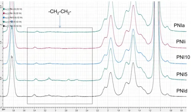
Figure 2.3. 1H NMR spectra of PNIPAM synthesized at different monomer concentrations and different initiator concentrations ... 61
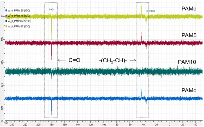
Figure 2.4. 13C NMR spectra of PAM synthesized at different monomer concentrations and different initiator concentrations ... 62
Figure 2.5. 13C NMR spectra of PNIPAM synthesized at different monomer concentrations and different initiator concentrations ... 62
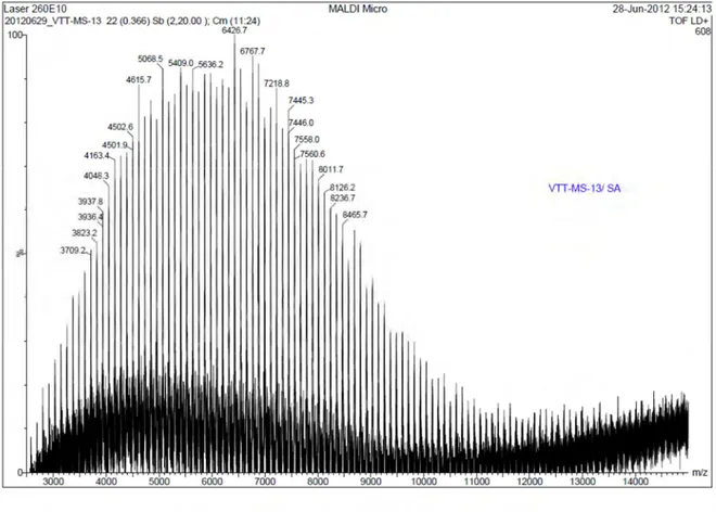
Figure 2.6. MALDI-TOF of amine terminated PNIPAM ... 63
Figure 2.7. FITC conjugated polyacrylamide ... 67
Figure 2.8. 13C NMR spectra of unmodified PNIPAM and PNIPAM modified with acrylic acid ... 69
Figure 3.1. AFM measurements of DOPA film deposited in sealed reactor ... 79
Figure 3.2. Evolution of DOPA film on silicon oxide wafer in various oxidation conditions . 81 Figure 3.3. Deposition kinetics analysis of DOPA films in various oxidation conditions ... 82
Figure 3.4. AFM topography of DOPA on silicon oxide wafer in various oxidation conditions ... 83
xii
List of schemes
Scheme 1.1. Oxidation mechanism of dopamine ... 42
Scheme 1.2. Strong non-covalent bond in DOPA from hydrogen bond ... 43
Scheme 1.3. Mix of non-covalent bond and covalent bonding in DOPA ... 43
Scheme 1.4. Attachment of DOPA to surface by chemical affinity ... 44
Scheme 1 5. Attachment of DOPA to surface by adsorption of catechol radicals ... 45
Scheme 2.1. Mechanism of chain transfer telomerization mechanism ... 57
Scheme 2.2. Conjugation of amine terminated polymer with FITC ... 67
Scheme 2.3. DCC/HOBt mediated amidation between amino terminated PNIPAM and acrylic acid ... 69
List of tables
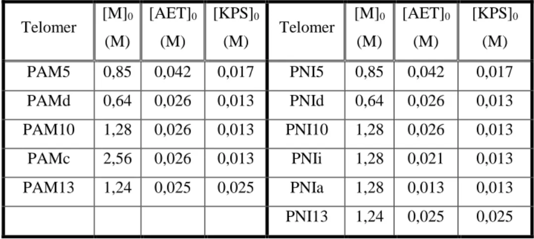
Table 2.1. List of synthesized polymers ... 58xiii
Introduction
Motivation and aims
The objective of the thesis was to develop a surface nonspecific technology for modifying solid/liquid interfaces of virtually any material used in the fabrication of multicomponent nano- and micro- fluidic devices. Our objective was accomplished by
using and optimizing mussel inspired surface chemistry based on sticky DOPA films. This new technology offered an opportunity for the homogenization of surface energy of all studied materials.
Lab-on-chips (LOCs), also called “micro total analysis systems (µTAS)”, is a newly
emerging field that represents a breakthrough in biomedical analysis and diagnosis. The aim of this field is to develop miniaturized and integrated fluidic devices that permit to decrease the time and cost of an analysis and that operate in an automated manner. From historical point of view, LOCs emerged from efforts to control liquid flow at subnanoliter scale in the early 1990s. Over the last twenty-five years, hundreds of microfluidic research groups and tens of microfluidic related companies have been established. At present, we can find some commercial products based on LOCs, such as iSTAT blood analyzer from Abbott Point-of-Care, glucose meter from Bayer Healthcare, DNA and peptide analyzer from Agilent.
To fabricate complex microfluidic devices, various solid materials, spanning from silicon, glass and plastics can be employed. The material of choice is often governed by the specific requirements of a given application while the price of the device can also play a crucial role. It was demonstrated that the cost of a microfluidic device can be dramatically reduced by applying hybrid technology in which silicon-based actuators are incorporated into non-expensive polymeric materials. On the other hand, it is well known that decreasing the size of any fluidic device leads invariably into increase of the surface-to- volume ratio. This often imposes the necessity to perform laborious, chemical or physical tailoring of the surfaces, especially in the micro- and nano-fluidic devices dedicated to biological applications. In general, surface modification approaches are developed case-by-case. They depend only on the properties of the modified materials and
xiv
tethering molecules. The methods most commonly employed for the functional modification of solid surfaces include the formation of self-assembled monolayers (SAMs) on metals, silane-based chemistry on silicon and glass substrates and polyelectrolyte layer-by-layer assembly on charged surfaces. It is clear that with these state-of-the-art surface modification approaches, it would be impossible to homogenize the surface properties in multicomponent or hybrid fluidic devices, integrating silicon, glass, metals, photoresists (e.g., SU8) and elastomers (e.g., polydimethoxysilane, PDMS) together.
The mussel adhesion to any solid surface in wet condition has now become the inspiration for the development of a universal surface functionalization approach, namely
mussel inspired surface chemistry (MiSC). To cling to rocks during high tide, mussel
secretes adhesive proteins that harden into solid, water-resistant glue. These biomimetic glues allow us to tailor the physic-chemical properties of almost any solid / liquid interface in a desired way.
In this study, we present a substrate-independent route for grafting end-functionalized polyacrylamide chains onto any solid surfaces through mussel inspired chemistry. Dopamine spontaneously oxidizes, under alkaline conditions, and forms highly reactive products that further polymerize and self-organize. This leads to a formation of thin-layer coating (DOPA films) that can be additionally modified with various molecules of interest. It has been shown in the literature that amines, thiols and carboxyl groups react with DOPA films. We have synthesized a variety of amino-terminated polyacrylamide and polyacrylamide derivative chains of different molecular weights. The polyacrylamide chains were end-tethered on different materials via a one-pot approach and the modified surfaces were thoroughly characterized.
The specific objectives of this study are:
-To synthesize amino-terminated polyacrylamide-based chains (PAM, PNIPAM) with variable molecular weights
-To characterize structural properties of synthesized polymers and to determine their molecular weights
-To optimize oxidation conditions of dopamine in order to achieve low-roughness DOPA-type thin films
xv
-To graft synthesized polymers to flat surfaces made of different materials using one-pot mussel inspired surface chemistry at optimized conditions
-To demonstrate the possibility to obtain non-fouling surfaces inside microfluidic devices
Thesis outline
This thesis is organized into four chapters and a general conclusion.
In the first chapter, the literature overview on the solid / liquid interfaces (SLIs) and the mussel inspired surface chemistry (MiSC) is depicted. First we describe the omnipresence of solid / liquid interfaces and their growing importance in downscaling, i.e., in micro- and nano- fluidic devices. The state-of-the-art of the modification of SLIs is described here as well and it is shown that the surface chemistry is highly substrate-dependent. Consequently, we give a general overview on the mussel inspired surface chemistry and we describe the mechanism of this approach. It is shown that the MiSC is substrate-independent and that it can be utilized as a universal method for the homogenization of surface energy in microfluidic channels built from various materials.
The second chapter of the thesis describes the synthesis of the amine terminated polyacrylamide and poly(N-Isopropylacrylamide) by the chain transfer radical polymerization. The experimental conditions of synthesis and detailed characterization of the synthesized polymers by Fourier Transform Infrared Spectroscopy (FTIR), Nuclear Magnetic Resonance (NMR), Size Exclusion Chromatography (SEC), Matrix-assisted laser desorption/ionization Time-of-Flight (MALDI-TOF) mass spectroscopy are given here. The qualitative verification of the presence of amine end-group in the synthesized polymers, by fluorescent FITC labeling and HOBT/DCC mediated amidation, is also described in this chapter.
In the third chapter, wetting and homogeneity of surfaces modified by MiSC are investigated by water contact angle measurement and atomic force microscopy. The effects of oxidation kinetics on deposition kinetics and surface morphology are thoroughly examined here by the two techniques. The results of this study are utilized to design optimized experimental condition, with the help of employing an oxidant, for obtaining faster deposition kinetics and surfaces with an ultralow roughness and much less
xvi
aggregation. Finally, we suggest applying these experimental conditions for an easy modification of surfaces in nano- and micro-fluidic channels.
The last chapter presents our paper that was published in Sensors and Actuators B: Chemical (http://dx.doi.org/10.1016/j.snb.2014.01.085). The goal of this manuscript is to demonstrate the versatility and the generality of our substrate-independent surface modification strategy. We show that we can end-graft amino-terminated polyacrylamide chains onto virtually any solid surface. Moreover this strategy is easily applicable to the modification of wetting properties of heterogeneous materials in nano- and micro-fluidic devices by a simple manner. The modified surfaces under optimized condition are characterized by analytical surface techniques, including water contact angle measurements, atomic force microscopy, cyclic voltammetry, and by studying a protein adsorption by fluorescence microscopy. In conclusion, we point out four major advantages of our approach: (i) substrate independency, (ii) compatibility with grafting of biologically active molecules, such as enzymes, because it is accomplished in aqueous solutions (iii) possibility to regenerate a modified surface when necessary and, (iv) possibility to apply this approach for functionalization of sub-micrometer sized channels because it works in a low-viscosity regime.
At the end of this manuscript, we give a general conclusions and an outlook for a future work.
11
12
13 1.1.1. Introduction
In this section, a necessary background of the solid / liquid interfaces (SLIs) and the microfluidic devices are presented. We describe the omnipresence of solid / liquid interfaces and their growing importance in downscaling, i.e., in micro- and nano-fluidic devices. The state-of-the-art of the modification of SLIs is described here as well and it is shown that the surface chemistry is highly substrate-dependent. The state-of-the-art of the microfabrication of microfluidic devices is also presented here and, finally, it is suggested that there is a need to develop a universal technology for functionalizing of surfaces of such devices.
14
1.1.2. Omnipresence of solid / liquid interfaces (SLIs)
Solid / liquid interfaces play vial roles in governing a number of phenomena encountered in many fields including biology, chemistry, material science and nano- / micro-fluidics. The interfacial properties determine behaviors of not only the solid substrates but also the liquid itself. Let’s consider some examples of solid / liquid interfaces.
In biology, the most important solid / liquid interfaces are cell-membrane / water
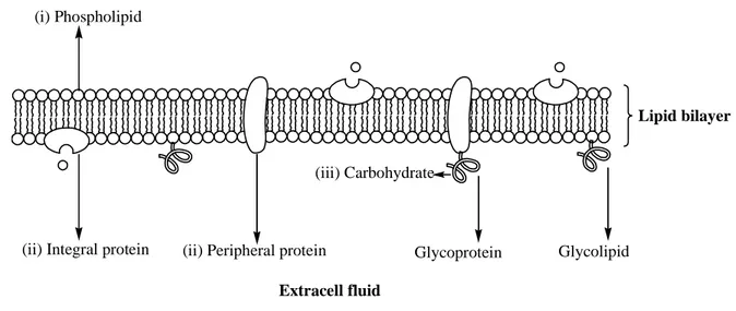
interfaces. The plasma membrane encloses the cell and defines the boundary between the cytoplasm and the extracellular environment. Albert et al., (2008) has given a comprehensive study about the structure of cell-membrane and its roles in cellular processes [1]. Despite their differing function, all biological membranes have a common general structure: a mosaic liquid membrane that consist lipid molecules (mostly, phospholipids) and membrane proteins [2]. The lipid molecules are arranged in a lipid bilayer to which proteins are embedded (see figure 1.1). Those parts within cell membrane serve different functions in extracellular processes. The lipid bilayer provides fluid structure of the membrane and also acts as a relatively impermeable barrier to the passage of most water soluble molecules. Although lipid is the major component of cell membrane (about 50% of the mass of most cell membrane), the membrane proteins are responsible for most membrane functions. They act as transport proteins, enzymes, specific receptors, and so on. For example, the peripheral proteins that span from one side to the other side of lipid bilayer act as membrane transport proteins to selectively transport substances (oxygen, nutrients, and wastes) in and out of the cell [3, 4]. There are two classes of membrane transport proteins: transporters and channels. Whereas transmembrane movement mediated by transporters can be either active or passive, solute flow through channel proteins is always passive [1]. Differing from peripheral proteins, the integral proteins stay on one side of membrane and can slide around the membrane. These proteins (e.g., actin) are involved in maintaining the shape and mobility of cell [5, 6]. Certain peripheral proteins (e.g., hydrolase, phospholipase, cholesterol oxidase, and etc) can also act as an enzyme to catalyze reactions in the cytoplasm [7, 8]. The glycoproteins (e.g., immunoglobins, histocompatibility antigens, and etc) that contain proteins and carbohydrates are usually involved in cell recognition which is part of immune system [9,
15
10]. Certain glycoproteins (e.g., Human chorionic gonadotropin (HCG), thyroid-stimulating hormone (TSH)) can also act as receptors in cell signaling [11, 12].
(ii) Integral protein (ii) Peripheral protein (i) Phospholipid Lipid bilayer (iii) Carbohydrate Glycoprotein Glycolipid Extracell fluid Cytoplasm
Figure 1.4. Illustration of a cell-membrane: (i) The phospholipids are arranged in a bilayer with
hydrophilic polar phosphate heads facing outwards and hydrophobic non-polar fatty acid tails facing each other in the middle of the bilayer; (ii) The proteins can span from one side of the phospholipid bilayer to the other (integral proteins), or stay on one of the surfaces (peripheral
proteins); (iii) Carbohydrate chains are often bound to the proteins (Glycoprotein), or to the
membrane phospholipids (Glycolipid).
In chemistry, the properties of solid / liquid interfaces that determine the surface area
available for contact between reactants are critical factors to control reaction rate. For example, electrochemical reactions are strongly dependent on the quality of metal surfaces on which they take place. A polymeric coating that is deposited on oxidizable metal surfaces (e.g., iron, copper, and aluminum) is available to protect them from the corrosion [13]. In electrochemical analysis, the properties of electrodes (e.g., cleanness and conductivity) are critical factors that determine the accuracy and reproducibility of obtained results [14]. And in heterogeneous catalysis where the phase of catalyst (e.g., metals) differs from that of reactants, the rate of catalytic reactions is strongly affected by the properties of catalyst / solvent interfaces [15, 16].
16
In material science, properties of hybrid materials (e.g., implants) is controlled by their
facial behaviors. Hybrid materials consist of inorganic moieties with high physical strength and organic moieties that have to be biocompatible. Only a thin layer of organic coating is sufficient to change completely behaviors of underlying materials as well as to allow the control of its interaction with surrounding environment. For example, the coatings of biodegradable synthetic polymers (mostly PL, PGA and their derivatives) are ideally suited for orthopedic applications where a permanent implant is not desired [17, 18].
Figure 1.5. Animation of scaling laws at nano- / micro-scale: The surface forces are dominant at
nano- / micro-scale. It would take a significant effort for an ant to free a comrade imprisoned in a bubble. At the scale of an ant, capillary forces are very significant with respect to the muscular forces the insect can exert [19].
And in nano- / micro-fluidics, the importance of solid / liquid interfaces in governing phenomena that happens on surfaces increases dramatically. Figure 1.2 is a famous animation about the predominance of surface phenomena on bulk phenomena in nano- / micro- systems. When reducing the size of a system, the scaling laws that describe the variation of physical quantities with the typical length change completely [19]. Consequently, the control of properties of surface of microchannels becomes extremely important in order to regulate all phenomena that happen in a microchannel, such as biomolecular interactions, separation process in chromatography, Electro-Osmosis Flow (abbreviated EOF) and molecular adsorption on surfaces [20, 21]. For example, the EOF that comes from the interaction between and the charged walls (e.g., silica or plasma treated PDMS) starts to be observable when their typical size of a microchannel falls to
17
about several hundred micrometers [19]. When these surfaces are in contact with aqueous solution at pH>2, a negatively charged layer is formed from its silanol groups (Si-OH). The ions that are close to surface can bind firmly or loosely to it. When applying a voltage, the ions that loosely attach to surface starts to move then drag the liquid with it. This liquid motion is known as EOF. Another common problem encountered in microfluidics is the adsorption of organic molecules on inner walls of microchannels. The non-specific adsorption of moieties may lead to significant loss of sample. In effort to eliminate the surface adsorption, the microchannels can be modified with a polymer coating that is bound non-covalently or covalently to surface [22].
1.1.3. Control of properties of SLIs
In many decades, a vast amount of methods have been developed to coat polymer films on surfaces. The methods in which strong non-covalent bonding or covalent anchoring were constructed are the preferred choices to fabricate polymer films since they meet almost fundamental requirements of thin film deposition, for instance, controllable thickness, adjustable functionality, high homogeneity and long-term stability. In general, all current methods to control polymeric SLIs show certainly serious drawbacks in spite of their advantages, especially the surface specificity for a given modification chemistry. This fact requires the innovations of universal techniques which are independent of the nature of surfaces. Here we point out the necessity for surface specificity in some common approaches: self assembled mono-layers (SAMs), grafted polymer brushes and adsorbed polymers layers.
1.1.3.1. Self-assembled monolayers (SAMs)
Self-assembled monolayers (SAMs) are ordered molecular assemblies formed by the adsorption of a functional active surfactant from solution onto a solid surface [23]. Since its introduction in 1980s, SAM has attracted significant attention as the best candidate to tailor thin polymer films. This method allows us to easily decorate interfaces with limitation of surface defects and structure control at nanoscale. We can flexibly utilize this method for modifying surfaces made of a wide range of materials. Adapting to the surface chemistry of substrates, different anchoring chemistries can be applied. Here we consider the two most popular SAMs: thiolization and silanization (see figure 1.3).
18 Si O O O Si O O O Si O O O Si O O O S S S S S S S S
Figure 1. 6. Illustration of Self-assembled monolayers: Silanization (left) and Thiolization (right).
Thiolization is the adsorption of organosulfure on noble metal surfaces. The thiols (e.g.,
alkyl thiol) assemblies can be spontaneously adsorbed by immersing freshly clean metal substrate (e.g., gold) into dilute thiol solutions in an organic solvent. This is based on the high affinity between organosulfures and metal surfaces [24]. The interest in alkanethiol SAMs stems from their stability and ease of preparation [25]. In addition, the organic monolayers that adsorb onto surfaces are usually well-organized even at nano-scale [26]. The metal surfaces modified by this method show potential applications in biosensors, biomimetics, and anti-corrosion [27]. Despite of its advantages, thiols, in general, show low physical and chemical stability due to their facile oxidation. And above all, this
method works only on metal substrates with gold being the best candidate for this chemistry.
Silanization is the assembly of organosilicon derivatives onto silicon oxide, quartz,
glass, mica, etc. A simple immersion of the mentioned substrates into dilute solution of silanes (e.g., OTS, APTES) can spontaneously form these organic assemblies on surfaces [28, 29]. This results from the chemical reactions between compounds containing silane groups and surfaces containing silicon oxides [29]. In this method, the molecules that anchor to surfaces can self-assembly into highly ordered monolayers [30]. The surfaces modified by this method have received considerable attention in biology and microfluidics [31]. However, the high moisture-sensitivity of silane molecules (particularly in case of chlorosilanes) requires us to handle carefully these chemicals during the assembly steps.
19 1.1.3.2. End-tethered polymers at SLIs
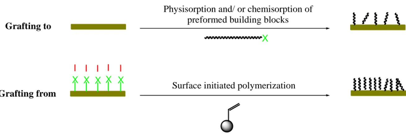
To graft polymer chains onto surfaces, the covalent bonding is the preferred choice in most cases [32]. There are two main methodological strategies to graft a polymer brush: (i) “grafting to” and (ii) “grafting from” (see figure 1.4).
X X X X X
I I I I I
Physisorption and/ or chemisorption of preformed building blocks
Surface initiated polymerization
Grafting to
Grafting from
X
Figure 1.7. Adaptable approaches to grafting polymer brushes on a wide range of materials:
“Grafting to” - Physisorption and/or chemisorptions of functionalized polymers on pretreated surfaces; “Grafting from” – Surface initiated polymerization of monomers on surfaces where initiators was pre-immobilized.
(i) Grafting to - low density - mushroom regime
In “grating to” methods, the polymer chains that were functionalized with reactive functional groups are grafted to a surface. The common reactive functional groups include thiols, silanes, amino or carboxylic groups. This technique usually shows low grafting density due to “excluded volume effect”. The repulsion between already grafted polymer chains and the incoming new one from solution can perturb its attachment onto a surface [33]. In this case, the polymer chains are tethered on surfaces in a low-density, mushroom regime.
(ii) Grafting from – high density – brush regime
In “grafting from” methods, the monomers are polymerized from surfaces that were previously modified with initiators. This strategy shows much higher grafting density compared to that of “grafting to” strategy. With the advances in polymer synthetic
20
methodologies and their adaptation to surface chemistry, these methods allow us to graft polymer chains on a variety of material surfaces with controllable properties. They can be implemented with almost all available polymerization techniques: ring opening metathesis polymerization (ROMP), nitroxide-mediated polymerization (NMP), atom transfer radical polymerization (ATRP), single-electron transfer living radical polymerization (SET-LRP), or reversible addition fragmentation chain transfer (RAFT) polymerization [32]. In this case, the polymer chains are tethered on surfaces in brush regime where they are stretched away from grafting surfaces like bristles in a brush [34].
Polymer brush has been studied in many decades. It was first noted as densely tethered polymer chains on interfaces in 1976 by Alexander and de Gennes [33]. These scientists have established the foundation for theoretical analysis based on scaling theory to study polymer brushes. They have pointed out the “excluded volume effect” (a kind of steric effect) in which the repulsion is set up between polymer chains due to spatial confinement. At sufficiently high grafting density of polymer chains on surfaces, an entropy barrier is established. That energy fence forces polymer chains to repulse each others, stretch away from surfaces, as well as repel external objects that approach surfaces. Therefore, polymer brushes exhibit anti-fouling properties and minimize the adsorption of molecules on solid surfaces.
1.1.3.3. Adsorbed polymer layers
Polymers can adsorb from solution onto surfaces if the interaction between the polymer and the surface is more favorable than that of the solvent with the surface and/or the polymer [35]. This can be accomplished either (i) by the adsorption of certain neutral polymers on specific surfaces or (ii) by the adsorption of polyelectrolytes (ionic or anionic) on charged surfaces.
(i) Neutral Polymers:
Some neutral polymers (e.g., PS, PDMA, PHEA, PEO, etc) show the ability to adsorb physically on solid surfaces (e.g., silica, glass) [36]. It was believed that the attractive interactions (e.g., Van der Waals forces, dipolar forces, hydrogen bonds, and etc) between polymer chains and the surface are the origin of polymer adsorption. The tendency of polymer chains (adsorb to surface or not) is determined by the nature of surface, absorbing polymer, and solvency condition [35]. If the polymer prefers the surface to the solvent,
21
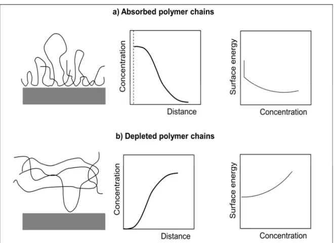
polymer chains are adsorbed to. On the other hand, we have polymer depletion if the polymer prefers the solvent to the surface. Figure 1.5 represents the differences between adsorption and depletion of polymer chains on a surface. We can see the surface energy drop in adsorption case that indicates the presence of adsorbed polymer chains on a surface. In contrast, the slow increase in surface energy implies that polymer chains can’t attach to the surface in depletion case.
Figure 1. 8. Adsorption and Depletion of polymer chains on surface: a) Illustration of absorbed
polymer chains, concentration profile and surface energy profile; b) Illustration of depleted polymer chains, concentration profile, and surface energy profile. Source: De Gennes [35].
An important application of polymer adsorption is the introduction of polymer to silica surface of a capillary. This is typically realized by rinsing the capillary with a solution containing the polymer of interest. The goal of introducing neutral polymers to the capillary is to eliminate sample-wall interactions as well as to stabilize Electro-Osmotic
22
Flow. For this purpose, hydrophilic neutral polymers (e.g., polysaccharide, PVA, PEO, PVP, PDMA) seem to be good candidates [37].
(ii) Polyelectrolytes:
Polyelectrolytes are polymers with ionizable groups (anions or cations) [38]. In polar solution (e.g., water), these ionizable groups can dissociate, providing charges on polymer chains. When a charged surface is put in a contact with a polyelectrolyte, the electrostatic interactions between those charged species of polymer chains and the surface are established. The electrostatic interaction which is generally stronger than other interactions (e.g., Van der Waals, dipolar forces, and hydrogen bonds) plays major role in governing polymer adsorption in this case.
The most important parameters controlling the adsorption behavior of polyelectrolytes at surfaces are: the charge density of the polymer chains (or degree of ionization); the net surface charge density; and the ionic strength [35]. In the situation where polyelectrolytes adsorbing on a surface of opposite charge, one can expect virtually any polymer chain to be adsorbed. For the adsorption of polyelectrolytes having the same sign as the surface, the absorbed amount of polymer chains is obviously less than that in the former case. The adsorption of polyelectrolytes generally decreases with the increase in ionic strength. Café et al., (1982) has studied the influence of ionic strength on the adsorption of sodium carboxymethyl cellulose and poly(acrylic acid) on barium sulfate surface and found that the increased ionic strength at alkaline pH allowed more polymer chains to adsorb to surface [39].
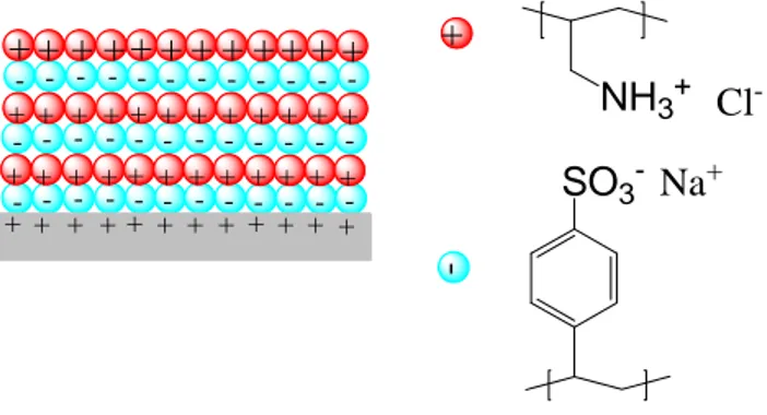
To achieve thicker polyelectrolyte films, Decher et al., has proposed the superposition of multiple polymer layers on a surface [40, 41]. He has performed the adsorption of consecutively alternating monolayers of anionic polyelectrolyte (polyalyaminehydrochloride) and cationic polyelectrolyte (sodium salt of polystyrene sulfonate) on aminopropylsilanized quartz that was previously protonated with acidic solution (as shown in figure 1.6).
23 - - - -+ NH3+ Cl -SO3- Na+ -- - - -+ + + ++ + + + ++ + + -- - - -++ + +++ + + ++ + + -++++++++++++ ++ + ++ ++ ++ + + +
Figure 1. 9. Example of adsorption of polyelectrolytes on surfaces: Consecutively alternating
adsorption of polyalyaminehydrochloride (in red) and sodium salt of polystyrene sulfonate (in cyan) on protonated aminopropylsilanized fused quartz [40].
1.1.4. A microchannel - scaling laws (importance of Surface to Volume ratio)
Microfluidics is a young discipline that studies the fluid flows circulating in artificial microsystems [42]. Since its introduction in 1990s, a vast of microfluidic systems has been fabricated, for example, electrophoretic separation systems, or micromixers, DNA amplifiers, microcytometers, and chemical microreactors. These systems were employing integrated microchannels as transportations of fluid flows. We discuss here some physical phenomena in those microchannels, and above all we evaluate the competition between facial phenomena and bulk phenomena in down-scaling.
1.1.4.1. Scaling laws in down-scaling: the predominance of surface forces on volume forces
To study physical phenomena in microchannels, it is important to consider scaling laws. A scaling law signifies the law of the variation of physical quantities with the size l of
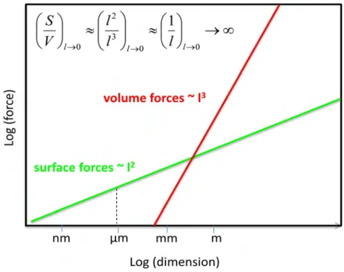
a system or an object [42]. The general rule of thumb for scaling laws is: When reducing the size l to a certain value, the quantities that are associated with the weaker exponent
become dominant. As a result, the volume forces (~l3) become negligible with respect to surface forces (~l2) in micro- or nano- systems (see figure 1.7). With the predominance of facial forces on bulk forces, some traditional phenomena, that we are used to at macroscale, disappear while a series of new phenomena occur in these systems.
24
Figure 1.10. Scaling laws in down-scaling: the predominance of surface forces on volume forces.
1.1.4.2. Dimensionless numbers in microfluidics
The relative importance of physical phenomena in microfluidic systems is generally evaluated by dimensionless numbers. Two most often mentioned numbers in microfluidics are: Reynolds number (relating inertial forces to viscous forces) and Peclet number (relating convection to diffusion). We will discuss here how these dimensionless numbers scale with the typical length of a microfluidic system, i.e. channel size, and how they indicate physical changes in down-scaling.
(i) Reynolds numbers: dominance of viscous stress
The Reynolds number is defined as the ratio of inertial forces and viscous forces: η Ul f f R v i
e = = where fi is the inertial centrifugal force density, fv is the viscous force density, l is the spatial scale, U is the characteristic velocity of the fluid, and η is its kinematic viscosity [42].
When a fluid flows through a microchannel, typical fluid velocities do not exceed a centimeter per second and widths of channels are on the order of tens or hundreds of
25
micrometers; it follows that, in general, Reynolds numbers in microfluidic systems do not exceed 100 [42]. As a result, the viscous forces are dominant over inertial forces.
In the situation where viscous forces overwhelm inertial forces, the fluids flow slowly in parallel layers without interruption between fluid layers. That simple fluid regime is known as laminar flow [43]. The simplification of fluid dynamics provides us the possibility to conduct precisely controllable processes, i.e. chemical reactions in laminar flow reactor.
(ii) Péclet numbers: dominance of diffusion
The dispersion Peclet number (Pe) characterizes the relation between transport of solute
due to convection and diffusion. In the case of a microchannel, it is given by
D Ul l Z
Pe = = ,
where Z is the moving distance of fluid (relating convection), U is the characteristic flow velocity, l is the size of the system, and D is the diffusion coefficient of the solute [42].
In practice, microfluidic systems work at the average values of Peclet number (between 0.1 and 100) and diffusion is the major mixing mechanism of fluid [43]. As a result, the mixing velocity is slow in microchannels. In addition, the Taylor dispersion that spreads molecules along the direction of the flow is pronounced as (Dz ∝Pe2D) and it contributes to fluid mixing in microchannels [44].
1.1.4.3. Adsorption phenomena
Adsorption is the phenomenon of the accumulation of a substance at surfaces. In microsystems, the adsorption of biological samples on surfaces of microchannels is a major concern.
It was known that biomolecules, e.g. proteins, can strongly adsorb to silica surfaces, leading, for instance, to considerable peak broadening and asymmetry in electrophoretic separations [45] and/or to sample loss in microfluidic devices. Such adsorption is stemmed from electrostatic and / or dipolar interactions between proteins and silica surface. Indeed, the silica surface becomes negatively charged in contact with electrolytes at pH greater than 2 due to presence of silanol groups. Therefore, electrostatic interactions might occur between silanol groups on surface and proteins that generally contain charged species [46].
26
Proteins can also physically adsorb to PDMS surfaces [47], interfering with the usability of PDMS-based microfluidic devices. Hydrophobic and porous surfaces like PDMS are known to be favorable for protein adsorption [48].
As mentioned above, the miniaturization of a system tends to enhance interfacial phenomena, in general, and surface adsorption, in particular. It’s clear that the adsorption at solid/liquid interfaces must be minimized to avoid a sample loss and the deterioration of analytical performances of microfluidic systems.
1.1.5. Microfluidic devices (lab-on-chips)
1.1.5.1. Commercialization of microfluidic devices
Lab-on-chip (LOC), also called “micro total analysis system (µTAS)”, is a newly emerging field that represents a breakthrough in biomedical analysis and diagnosis. From historical point of view, lab-on-chips (LOCs) emerged from efforts to control liquid flow at subnanoliter scale in the early 1990s. Over the last twenty-five years, hundreds of microfluidic research groups and tens of microfluidic related companies have been established. iSTAT blood analyzer (from Abbott Point of Care, USA) is among the first commercially successful LOC products. This LOC device is an advanced blood analyzer that provides real-time, lab-quality results within minutes, using only several blood drops. Such a device is equipped with different cartridges which contain variety of chemically sensitive biosensors on a silicon chip, allowing a comprehensive menu of specific diagnostic tests (chemistries, hematology, blood gases, coagulation, and cardiac markers). Another interesting microfluidic device is the glucose meter (from Bayer Healthcare, Germany), which uses multiple strips integrated with optical detectors in a single package for diabetic patients. The DNA and peptide analyzer from Agilent Technologies permit the identification of an object (e.g., a virus) from characteristic sequences of genes. The future development of LOCs will provide us with a variety of fluidic devices for diverse biomedical applications.
1.1.5.2. Advantages of miniaturization and integration
Miniaturization and integration of microfluidic devices lead to many benefits. Firstly, the cost of fabrication of microfluidic devices decreased significantly by reducing the consumption of manufacturing materials. Secondly, the portability of miniaturized and
27
integrated devices is easier. Thirdly, it is obvious that the consumption of reagents and analytes can be reduced significantly by decreasing the volume of a test. Lastly, the time of analysis can be decreased by integrating multiple tasks on the same microfluidic platform and performing analyses in serial and / or parallel manner.
Additionally, the predominance of surface phenomena on volume phenomena (mentioned in section 1.1.4.1) offers entirely new applications that are inaccessible to fluidic systems at macroscale. For instance, passive liquid actuation based on capillary forces that is employed, for instance, in capillary test strips would not work on macroscale. Other cases in which we take advantage of working on microscale are, electro-osmotic flow actuation, hydrophobic valves in microfluidic devices [49], and surface immobilized enzymes in enzymatic reactors and/or single cell studies in fluidic systems [50].
1.1.5.3. Microfabrication of microfluidic devices
Depending on targeted application and cost of devices, different materials, i.e. silicon, glass, quartz, metals and polymers can be employed in manufacturing. The choice of manufacturing technique must be compatible with the chosen material. We present here current microfabrication techniques that are widely used to fabricate microfluidic devices.
(i) The choice of materials
In the early days of LOCs, silicon and glass were major materials for manufacturing microfluidic devices [51]. The use of those well-known materials allows us to enjoy the benefits of well-developed and broadly utilized techniques in microelectronics, i.e.
photolithography and etching. Despite of their relatively high price, these materials are still required for fabrication of some active elements (e.g., thermal actuators and detectors) that can suffer from high temperature. Weak thermal expansion (coefficient of thermal expansion α ~ 2.33×10⁻⁶ at room temperature, for silicon) inhibits the distortion of microstructures as heating. Silicon is a good conductor that allows the fast thermal dissipation which is really important in miniaturized systems.
The metals (e.g., Au, Ag, Cu) are necessary for construction of active elements that are electrically conductive (e.g., electrodes, magnetic coils) in LOCs. Metal- based microstructures are generally formed by electron lithography techniques. [52].
28
In several years, the polymers (epoxy, SU8, COC, PDMS, and etc) that are much cheaper than silicon and glass have become the materials of choice for manufacturing low-price LOCs [53]. Polymer – based microstructures can be formed by various fabrication techniques: molding, casting, and etc.
To satisfy the low cost of device, Charlot et.al, (2008) has currently proposed to fabricate LOCs by integrating active elements (Si, metals) into a system of channels made of cheap materials, such as PDMS and/or SU8 and calling them hybrid microfluidic devices or hybrid LOCs [54].
(ii) Photolithography
Photolithography is a process that plays a central role in microfabrication. This technique is utilized to design defined microstructures on a substrate. It is realized by using the light (X-ray, electron, or photon) to transfer geometric pattern from a photomask to a photoresist on a substrate [53]. Typically, a photolithography process groups together following steps: fabrication of a photomask; deposit of a photoresist on a substrate; and transfer of a pattern from photomask to photoresist.
Fabrication of a photomask: A photomask is a transparent plate on which a defined opaque pattern is deposited. In practice, photomasks are generally quartz plates covered with defined patterns in chrome. Taking benefits from the development of electronic lithography techniques, these techniques are often used to fabricate photomask with a precision on the order of a fraction of a micrometer [42].
Deposit of a photoresist on a substrate: A photoresist film is prepared on a solid substrate (silicon or glass) that is ready for a pattern transfer. The highly photosensitive resists, i.e. SU8 and AZ-series, are among the materials of choice [42]. The deposit is made using spin coating technique in which a layer of photoresist is deposited on a spinning surface. A drop of photoresist solution at certain volume (3-4 ml, in practice) is first dispensed at the center of a substrate. The substrate is then rotated at high velocities (several thousand rpm) to allow the spreading of the photoresist over its surface. After a sufficient rotation time (a few minutes), a layer of photoresist with a stable thickness is formed on a substrate. The thickness of the obtained film varies with the viscosity, initial concentration of photoresist solution, and rotation velocity of the substrate. At the end of this step, the resist is heated slightly (i.e., 90°C, 2 minutes) to completely remove a solvent.
29
Pattern transfer from photomask to photoresist: The resist film is exposed to a light beam crossing the photomask. The prepared photoresist film is previously aligned with the photomask in an aligner (e.g., MA-6 mask aligner from SUSS MicroTec, Germany). The light beam initiates reactions in the photoresist, therefore change its solubility in certain solvents.
There are two types of resists: positive (e.g., AZ-series) and negative (e.g., SU8). In the former case, the irradiated areas become soluble and removable by an organic solvent, while the non-irradiated areas are polymerized and insoluble. In the later case, the irradiated areas become insoluble while the other areas can be dissolved and removed by an organic solvent.
30 (i) (ii) (iii) (iv) (v) (vi) (viii) (ix) (vii)
Figure 1.11. Illustration of Wet etching of glass: (i) Clean substrate; (ii) Deposit protection
material; (iii) Deposit photoresist using spin coating; (iv) Expose the resist to UV radiation through a mask (UV radiation only transmits through transparent areas); (v) Develop the photoresist (exposed areas are eliminated in case of positive resist while remained in the case of negative resist); (vi) Etch protective material and (vii) remove the resist from the substrate; (viii) Etch the glass; (ix) Remove mask material from the substrate. Source: P. Abgrall and A-M Gué [53].
31 (iii) Etching
Etching belongs to bulk micromachining technologies that form micro-patterns in the substrate itself. In this technique, microstructures are etched on substrate by using a proper physicochemical method. It can be achieved by either wet etching (use of chemicals, i.e. HF or KOH) or dry etching (use of ionized gas, plasma) [53].
Figure 1.8 shows an example of wet etching of glass. First, the micro patterns on the substrate are defined by photolithographically (i→v). The desired microstructures on the substrate are obtained by etching of the glass substrate and removing the protective material (vi→ix).
(iv) Molding
Molding is a replication technique that is widely used for polymer-based microfluidic devices. The molding that employs PDMS offers an elegant solution for microfabrication. The benefits of PDMS-based LOCs are: visualization of flows in transparent PDMS channels; variable elasticity depending on PDMS/ reticulating agent; water tightness of microfluidic connections due to elastomeric property of PDMS; self-adhesion to glass, silicon or PE due to temporary hydrophilicity of oxidized PDMS surface (after oxygen plasma treatment or immersion in a strong base); and easy peeling off from substrates due to low surface energy.
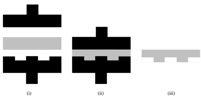
Figure 1.9 describes molding process that is often used in clean room to manufacture PDMS- based LOCs. We have used this process to fabricate PDMS microchannels that were used in this work (chapter 4). The SU8 mold was first patterned by photolithography (i), the PDMS was then molded on SU8 mold, peeled off from substrate (ii), and finally the formed channels in the PDMS substrate are closed by a glass plate after O2 plasma
32
(i)
(ii)
(iii)
Degas PDMS solution
Pour PDMS solution on SU8 mold Annealling, 90°C, 1h
Peel off PDMS pattern
(iv)
Figure 1. 12. Illustration of Molding process of PDMS microchannels (i) SU8 mold is
photolithographically patterned; (ii) PDMS pattern is casted with using SU8 mold; (iii) PDMS pattern is sealed by glass wafer with using plasma treatment; (iv) An example of 1D microchannel (H×W×L = 10µm×300µm×3cm). Protocol developed by LAAS laboratory.
(i) (ii) (iii)
33 (v) Casting
Casting is another replication technique that can be applied to manufacture polymer- based LOCs. In this technique, the polymer is pressed into a heated deformable material, then cooled, and finally separated to obtain a defined microstructure.
Figure 1.10 illustrates the principle of casting technique. The mold (a rigid material, i.e. silicon or a metal) is first heated to high temperature (e.g., 170°C for PMMA) at which the polymer can deform considerably under pressure. The polymer is then pressed by heated mold at high pressure (tens of bars) to form patterns on it (embossing). Then the polymer bulk is removed from the mold and left cooling until a stable solid structure is obtained (demolding). The commonly employed casting materials include PMMA, PC, PE, PET, PVC, PEEK [42].
34 1.1.6. Conclusions
We have shown here that solid / liquid interfaces (SLIs) play a crucial role in many different processes in biology, chemistry and physics. Along the same lines, we also put in the evidence that SLIs become extremely important for small objects, such as particles and/or nano- and micro-channels. This can be explained through scaling laws as the volume forces decay much faster than the surface ones, with decreasing size of an object. It has been well known for many years that SLIs play a crucial role in microfluidic devices and that their role will grow even more as we move to nano-fluidics. Consequently, several approaches to the modification of SLIs have been developed over the years and they are based on formation of more or less organized organic layers on a solid surface. We have described the major modification schemes of the SLIs, such as the formation of self-assembled monolayers on silicon and/or metal surfaces, formation of end-tethered polymers brushes and adsorption of neutral or charged polyelectrolytes on various surfaces. All these approaches have their advantages and disadvantages but they all can be characterized by the requirement of a surface specificity, i.e., the surface chemistry dictates the material of choice that will be modified. The situation becomes even more difficult or even impossible to realize when surfaces of microfluidic devices built from several different materials have to be functionalized.
We have developed in this thesis work a surface modification scheme that is substrate independent (works on all solid surfaces) while it offers a great variability and choice in the physic-chemical-biological properties of the modified surfaces, spanning from passive non-fouling, through stimuli-responsive to biologically active solid/liquid interfaces.
35 References
[1] Alberts B., Johnson A., Lewis J., Molecular biology of the cell, 4th ed., Garland Science
Press, USA (2002).
[2] S.J. Singer, G.L. Nicolson, Science, 1972, 175, pp 720-731.
[3] Bertil Hill, Ion channels of excitable membranes, 3rd ed., 2001, Sinauer Associate Publisher, USA
[4] W.D. Stein, W.R. Leib, Transport and Diffusion across Cell Membranes, 1986, Academic Press, USA.
[5] Thomas D. Pollard, John A. Cooper, Science, 2009, 326 (5957), pp 1208-1212.
[6] Sheryl P. Denker, Derek C. Huang, John Orlowski, Heinz Furthmayr, Diane L Barber, Molecular Cell, 2000, 6(6), pp 1425-1436.
[7] (a) Alan Fersht, Structure and Mechanism in Protein Science: A Guide to Enzyme Catalysis and Protein Folding, W. H. Freeman Press, USA (1998); (b) Robert A. Copeland, Enzymes: A Practical Introduction to Structure, Mechanism, and Data Analysis, Wiley Publisher, USA (2000).
[8] (a) Holmquist M., Current Protein and Peptide Science, 2000, 1(2), pp 209-235; (b) R. M. C. Dawson, On the mechanism of action of phospholipase A, Biochem J., 1963, 88(3), pp 414–423.
[9] Barry M Gubiner, Cell, 1996, 84(3), pp 345-357.
[10] Marinos C., Dalakas M.D., Neurology, 1998, 51 (6), Suppl 5 S2-S8.
[11] (a) Edward Bittar, Membranes and Cell Signaling, 1997, JAI press, England; (b) C.M. Revankar, D.F. Cimino, L.A. Sklar, J.B. Arterburn, E.R. Prossnitz, Science, 2005, 307 (5715), pp 1625-1630; (c) Stephen S. G. Ferguson, Pharmacological Reviews, 2001, 53(1), pp 1-24.
[12] J.H. Duncan Bassett, Graham R. Williams, Trends in Endocrinology and Metabolism, 2003, 14(8), pp 356-364.
[13] (a) C.A. Ferreira, S. Aeiyach, A. Coulaud, P.C. Lacaze, J. Appl. Electrochem., 1999, 29, pp 259–263; (b) G.A. Smitha, O.I. Jude, Polymer, 2001, 42(24), pp 9665–9669; (c)
T. Tüken, G. Arslan, B.Yazici, M. Erbil, Prog. Org. Coatings, 2004, 49(2), pp 153–159. [14] Allen J. Bard, Larry R. Faulkner, Electrochemical Methods: Fundamentals and
Applications, 2rd ed., Wiley Publisher, USA (2000).
36
[16] J. M. Thomas, W. J. Thomas, Principles and Practice of Heterogeneous Catalysis, Wiley Publisher, USA (1996).
[17] C.M. John, J.T. Arthur, Biomaterials, 2000, 21(23), pp 2335–2346.
[18] Freed L.E., Vunjak-Novakovic G., Biron R.J., Eagles D.B., Lesnoy D.C., Barlow S.K., Langer R., Biotechnology, 1994, 12(7), pp 689-693.
[19] Patrick Tabeling, Introduction to Microfluidics, Oxford University Press, UK (2005). [20] F. Tagliaro, G. Manetto, F. Crivellente, F.P. Smith, Forensic Sci. Int., 1998, 92 (2-3),
pp 75–88.
[21] H. Stellan, J. Chromatogr. A, 1985, 347, pp 191–198.
[22] (a) Ken K.C. Yeung, Charles A. Lucy, Anal. Chem., 1997, 69 (17), pp 3435–3441; (b) John K. Towns , Fred E. Regnier, Anal. Chem., 1991, 63 (11), pp 1126–1132; (c) R. Nehmé , C. Perrin, Methods Mol. Biol., 1996, 984, pp 191-206.
[23] U. Abraham, Chem. Rev., 1996, 96, pp 1533–1554.
[24] G.E. Poirier, E.D. Pylant, Science, 1996, 272, pp 1145–1148.
[25] (a) D.B. Colin, E. Joe, M.W. George, J. Am. Chem. Soc., 1989, 111(18), pp 7155– 7164; (b) G.N. Ralph, L.A. David, J. Am. Chem. Soc., 1983, 105(13), pp 4481–4483. [26] (a) D.B. Colin, M.W. George, Science 240, 1988, pp 62–63; (b) D.P. Marc, B.B.
Thomas, L.A. David, E.D. Christopher, J. Am. Chem. Soc., 1987, 109(12), pp 3559– 3568 (1987).
[27] (a) Th. Wink, S. J. van Zuilen, A. Bult and W. P. van Bennekom, Analyst, 1997, 122, pp 43R-50R; (b) Anne L. Plant, Langmuir, 1993, 9 (11), pp 2764–2767.
[28] O. Steffen, J.R. Bart, N.R. David, Angew. Chem. Int. Ed., 2005, 44(39), pp 6282– 6304.
[29] H. Claudia, H. Stephanie, S.S. Ulrich, Chem. Soc. Rev., 2010, 39, pp 2323–2334. [30] S. Jacob, J. Am. Chem. Soc., 1980, 102(1), pp 92–98.
[31] Mingxian Huang, Eva Dubrovcakova-Schneiderman, Milos V. Novotny, Hafeez O. Fatunmbi, Mary J. Wirth, J. Microcolumn Separations, 1994, 6(6), pp 571–576.
[32] A. Omar, J. Polym. Sci. Part Polym. Chem., 2012, 50 (16), pp 3225–3258.
[33] (a) P.G. De Gennes, J. Physic Paris, 1976, 37, pp 1445–1452 ; (b) S. Alexander, Physic Paris, 1977, 38(8), pp 977–981; (c) M. Daoud, P.G. De Gennes, J. Physic Paris, 1977, 38(1), pp 85–93; (d) P.G. De Gennes, Macromolecules, 1980, 13(5), pp 1069– 1075; (e) P.G. De Gennes, Macromolecules, 1981, 14(6), pp 1637–1644; (f) P.G. De Gennes, Macromolecules, 1982, 15(2), pp 492–500; (g) P.G. De Gennes, J Phys Lett, 1983, 44, pp 241–246.
37
[34] (a) S.T. Milner, Eur. Lett., 1988, 7(8), pp 695–699; (b) S.T. Milner, T.A. Witten, M.E. Cates, Macromolecules, 1988, 21(8), pp 2610–2619; (c) S.T. Milner, T.A. Witten, M.E. Cates, Eur. Lett, 1988, 5(5), pp 413–418.
[35] P.G. De Gennes, Adv. Colloid. In. Sci., 1987, 27(3-4), pp 189–209.
[36] Eugène Papirer, Adsorption of polymer on silica surfaces, Marcel Dekker, USA (2000), pp 463.
[37] Horvath J., Dolník V., Electrophoresis, 2001, 22(4), pp 644-655.
[38] Andrey V. Dobrynina, Michael Rubinstein, Prog. Polym. Sci.,2005, 30, pp 1049– 1118.
[39] M.C. Cafe, I.D. Robb, J. Colloid. Interface Sci., 1982, 86(2), pp 411-421. [40] Gero Decher, Science, 1997, 277 (5330), pp 1232-1237.
[41] G. Decher, J. D. Hong, J. Schmitt, Thin Solid Films, , 1992, 210/211, pp 831-835. [42] Patrick Tabeling, Introduction to Microfluidics, Oxford University press (2005). [43] H.A. Stone, A.D. Stroock, A. Ajdari, Annu. Rev. Fluid Mech., 2004, 36, pp 381–411. [44] Geoffrey Taylor, Dispersion of solute matter in solvent flowing slowly through a tube,
Proc. R. Soc. Lond. A, 219,186-203 (1953).
[45] M. Graf, R. Galera Garia, H. Wätzig, Electrophoresis, 2005, 26(12), pp 2409–2417. [46] Irina Gitlin, Jeffrey D. Carbeck, George M. Whitesides,Angew. Chem. Int. Ed., 2006, 45, pp 3022 – 3060.
[47] J. Cooper McDonald, George M. Whitesides, Acc. Chem. Res., 2002, 35 (7), pp 491– 499.
[48] (a) L.J. Ho, K. Gilson, L.J. Whan, L. Hai Bang, J. Colloid. Interface Sci., 1998, 205(2), pp 323–330; (b) A. Yusuke, I. Hiroo, Biomaterials, 2007, 28(20), pp 3074–3082. [49] (a) Shulin Zeng, Chuan-Hua Chen, James C. Mikkelsen Jr., Juan G. Santiago, Sensors
and Actuators B: Chemical, 2001, 79 (2-3), pp 107-114; (b) Yanying Feng, Zhaoying Zhou, Xiongying Ye, Jijun Xiong, Sensors and Actuators A: Physical, 2003, 108 (1-3), pp 138-143.
[50] (a) Shuichi Takayama, Emanuele Ostuni, Philip LeDuc, Keiji Naruse, Donald E. Ingber, George M. Whitesides, Nature, 2001, 411, pp 1016; (b) McClain MA, Culbertson CT, Jacobson SC, Allbritton NL, Sims CE, Ramsey JM., Anal Chem., 2003, 75(21), pp 5646-5655; (c) Anna Tourovskaia, Thomas Barber, Bronwyn
T. Wickes, Danny Hirdes, Boris Grin, David G. Castner, Kevin E. Healy, Albert Folch, Langmuir, 2003, 19, 4754-4764; (d) Mathieu Foquet , Jonas Korlach , Warren R. Zipfel , Watt W. Webb , Harold G. Craighead, Anal. Chem., 2004, 76 (6), pp 1618–