1
Performance evaluation of an Organic Rankine
Cycle (ORC) connected to two-phase closed
thermosyphons
Van Long Lêa, Sébastien Declayeb, Xavier Dumasc, Ludovic Ferrandd and Vincent Lemorte
a The University of Liège, Liège, Belgium, vanlong.le@ulg.ac.be b The University of Liège, Liège, Belgium, Sebastien.Declaye@ulg.ac.be
c
CMI Industry, Guyancourt, France, xavier.dumas@cmigroupe.com
d CMI Industry, Guyancourt, France, ludovic.ferrand@cmigroupe.com e The University of Liège, Liège, Belgium, vincent.lemort@ulg.ac.be
Abstract:
This paper aims at evaluating the performance of a waste heat-to-power plant using an organic Rankine cycle (ORC) connected to two-phase closed thermosyphons (or gravity-assisted heat pipes or wickless heat pipes). The heat exchanger, made up of two-phase closed thermosyphons, is used for transferring heat from exhaust stream to ORC working fluid. In practice, a hot oil loop or a pressurized hot water loop or a saturated steam loop or even a direct evaporator is often used to transfer heat from heat source to ORC system. However, installing a heat exchanger directly in the hot gas paths of ORC system evokes the concerns for the flammability and/or toxicity of organic working fluids especially when the heat source has a relative high temperature. Also the use of an intermediate heat carrier loop such as thermal oil or saturated steam or pressurized water loop is relatively expensive and involves installation of relatively heavy components. A priori, the use of two-phase closed thermosyphons for capturing and transferring heat from a waste heat source to organic working fluid is less expensive than the use of an intermediate heat transfer loop and eliminates safety concerns as in the case of direct installation of an ORC evaporator in the hot gas paths.
Keywords:
Waste heat recovery, ORC, two-phase closed thermosyphon, performance evaluation.
1. Introduction
The present study has been realized in the framework of ORCAL (stands for waste heat recovery by means of ORC connected to gravity-assisted heat pipes or two-phase closed thermosyphons) project within collaboration between the University of Liège and C.M.I. (Cockerill Maintenance & Ingénierie) group. The main objective of this project is to recover heat from exhaust stream of a rolling mill reheating furnace using an ORC system connected to two-phase closed thermosyphons as shown in Figure 1. The existing furnace is already equipped a recuperator for preheating the combustion air entering the furnace. The additional waste heat recovery system (thermosyphons-ORC system) is placed upstream the air-preheater where the exhaust gases are characterized by a temperature of about 820 °C. The temperature drop of the exhaust gas across the thermosyphons heat exchanger is set to 200 °C for a good balance between the recovered heat and the future redesign of the air-preheater.
In practice, an intermediate heat carrier loop (e.g. pressurized water, saturated steam or thermal oil loop) [1] is often used to transfer heat from exhaust stream to ORC system. However, using a heat carrier loop increases the complexity and the investment cost as well as the operating cost of waste heat to power plant. A direct exchange between hot exhaust stream and ORC working fluid may be used to improve the cycle efficiency and cost by eliminating the pumps, heat exchangers and other cost of the additional heat carrier loop. However the installation of the ORC evaporator directly in the hot gas paths poses concerns for the decomposition of the organic working fluid at high temperature as well as the safety due to the flammability and/or toxicity of organic compound [1,
2
2]. Using an ORC system connected to two-phase closed thermosyphons, the cycle efficiency and cost will be improved by eliminating the pump and additional cost of the heat transfer loop while the organic working fluid is external to the hot gas path.
So far, there are not many scientific publications on using two-phase closed thermosyphons for transferring heat from exhaust stream to ORC system. The combination between ORC and heat pipes or two-phase closed thermosyphons is only reported in some patents [2, 3]. In the first patent [2], a special type of heat pipe, i.e. inorganic coated heat pipe or also called Qu-type heat pipe, is used for transferring heat from heat source, e.g. exhaust gases, to an ORC working fluid. As described in this patent, Qu-type heat pipes are a type of solid-state heat pipe which operates somewhat similarly to liquid-vapour heat pipes (e.g. two-phase closed thermosyphon) but do not use a fluid-vapour material to transfer heat from one end to other end of pipe. In a Qu-type heat pipe, the internal heat transfer material comprises three layers of various combinations of metals such as: Sodium, Beryllium, Manganese, Aluminium, Calcium, etc. The three layers can be applied to a conduit and then heat polarized to form heat transfer devices that transfer heat. In the second patent [3], the two-phase closed thermosyphons were used to recover the heat of fumes or exhaust gas by using an ORC system or a heat pump or a thermoelectric module. As claimed in the patent, the evaporator section of one or many two-phase closed thermosyphons are submersed in one fluidized bed of sand whose the average size is about 400 µm for improving the heat transfer between fumes and thermosyphons wall. Both technologies present the advantages for transferring the heat from hot fumes or exhaust gases to ORC working fluid. However they also present some disadvantages such as high manufacturing cost for Qu-type heat pipes, high cost and pressure drop for the combination between a fluidized bed and two-phase closed thermosyphons.
Figure 1. Schematic of waste heat recovery system using ORC connected to two-phase closed thermosyphons
3
This work aims at evaluating the use of traditional two-phase closed thermosyphons heat exchanger for transferring the heat from hot gases to ORC working fluid to improve the cycle efficiency and increase the profitability of the system.
2. Two-phase closed thermosyphon heat exchanger
The two-phase closed thermosyphon (also called gravity-assisted heat pipe or wickless heat pipe) is shown in Figure 2. An amount of working fluid (e.g. water, refrigerant, hydrocarbons, etc.) is placed in a tube from which the air and all other gases are then evacuated and the tube sealed [4]. The lower end (also called evaporator section) of the tube is heated causing the liquid to vaporise and the vapour to move to the cold end (also called condenser section) of the tube where it is condensed. The evaporator and condenser section are separated by an adiabatic section. The condensate is returned to the hot end by gravity. Since the latent heat of vaporization is large, considerable quantities of the heat can be transported with a very small temperature difference from end to end. Thus, the structure will have a high effective thermal conductance. One limitation of the basic two-phase closed thermosyphon is that the evaporator section must be situated at the lowest point for the return of the condensate [4]. The overall performance of thermosyphon in terms of thermal resistance is given by [5]:
tot T Q R (1) Where
Q rate of heat transferred by thermosyphon
T
effective overall temperature difference,
T,eT,c
totR overall thermal resistance of thermosyphon
The thermal resistances of a two-phase closed thermosyphon described in [6] can be seen in Figure 2.
Figure 2. Thermosyphon and thermal resistances diagram [7]
Where
1, 9
R R thermal resistances of combined convection and radiation at the outer surface of the evaporator and condenser, respectively.
2, 8
R R thermal resistances of conduction through the evaporator and condenser walls, respectively.
3, 7
4
4, 6
R R thermal resistances at the surface of the liquid-vapour interface in the evaporator and condenser. These resistances are small and can be neglected.
5
R thermal resistance due to vapour pressure drop from evaporator section to condenser section
10
R thermal resistance along the thermosyphon. This resistance is too large and can be neglected.
Figure 3. Schematic of a two-phase closed thermosyphon heat exchanger [8]
A two-phase closed thermosyphon heat exchanger in which groups of two-phase closed thermosyphon are arranged in a casing, the centre of which is partitioned, a high temperature fluid flows on one side, a low temperature fluid flows on the other side, thereby transferring the heat of the high temperature fluid to the low temperature fluid via fluid sealed in the two-phase closed thermosyphons, is shown in Figure 3. In many countries, the use of thermosyphon heat exchangers is quite new, but other countries, such as China, has applied this technology for decades [9]. The geometric flexibility [10], low maintenance, low cost and compactness make thermosyphon heat exchanger attractive when compared to the other technologies (e.g. tube-and-shell and plate heat exchangers) [9].
2.1. Two-phase thermosyphon working fluid and material
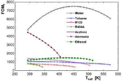
The selection of the working fluid is one of the most important parameters for thermosyphon design. Several aspects must be considered such as: range of working temperature, chemical compatibility between the working fluid and thermosyphon material, vapour pressure, stability, toxicity etc. A common method for selecting two-phase thermosyphon working fluid is to compare the different fluids in function of figure of merit (FOMt), which has the dimension 3/4 5/2kg
K s , defined as follow [4]: 1/4 2 3 l l lv t l k h FOM (2)
The thermo-physical properties that compose the figure of merit are dependent on the temperature level. The higher figure of merit is, the better the thermosyphon performance is. The operating temperature of thermosyphon situates between the temperature of fumes or exhaust gases and evaporating temperature of ORC working fluid. The heat transfer coefficient on the fumes side is much lower than the coefficient on the organic working fluid side (with phase change
5
transformation). As a consequence, the temperature of thermosyphon is closer to the temperature of ORC working fluid than fumes temperature. Based on this statement, the temperature of working fluid inside thermosyphon is probably within 150 – 300 °C (423 – 573 K). In this temperature range, the water presents a relative high figure of merit as shown in Figure 4. It seems to be logic to adopt this fluid considering other advantages such as high latent heat, stability, no-toxicity, availability, low price, and familiarity, etc. The main concern about water is the vapour pressure, which can increase significantly with the temperature. In these cases, the casing material must be selected so that it can be bear the vapour pressure [9].
Figure 4. Figure of merit for different two-phase closed thermosyphon working fluid
In turn, the selection of tube material is a very important parameter for the design of thermosyphon [9]. The tube has to be compatible with the working medium and the environment to stand the mechanical strength needs of the thermosyphon. The working fluid and tube material should not react chemically to avoid the generation of non-condensable gases which are one of the most common impurities of thermosyphon working fluid. During the operation, the non-condensable gases are pushed to the upper end of the condenser region of the thermosyphon, blocking part of the condenser and causing a reduction in the thermal performance of the device. The working fluid and the operating temperature are main input parameters for the selection of the tube material and thickness. Table 1 shows a list of compatibility between common tube materials and working fluids.
Table 1. Working fluid and tube material compatibility list [9]
Recommended Not recommended
Ammonia Aluminium, Steel, Nickel, Stainless steel Copper Acetone Copper, Silica, Aluminium, Stainless steel a
Methanol Cooper, Stainless steel, Carbon steel, Silica Aluminium
Mercury Stainless steel Nickel, Inconel, Titanium, Niobium
Water Copper, Monel, Silica a, b, Nickel a, b, Stainless steel a, b, Carbon steel a, b
Stainless steel a, b, Carbon steel a, b, Aluminium, Silica, Inconel, Nickel Dowtherm A Copper, Silica, Stainless steel b
Naphthalene Carbon steel, Stainless steel
Potassium Stainless steel, Inconel Titanium
Sodium Stainless steel, Inconel Titanium
Silver Tungsten, Tantalum Rhenium
a
Considered compatible for some authors and incompatible for others
b
6
3. Organic Rankine cycle
The ORC system operates in a similar way to the steam Rankine cycle system, but uses an organic compound instead of water as working fluid. Indeed, using organic fluids with higher molecular weight than water can result in greater turbine efficiency and thus less costly expanders. Furthermore, the low specific enthalpy drop of organic vapour requires a higher mass flow rate through the turbine for the same power output [11]. This allows the blades to be larger and satisfies the full-admission condition of the turbine, even for small power outputs. Consideration of these factors leads to higher nozzle and blade efficiencies [11]. The use of a high molecular weight working medium with a sufficiently low saturation pressure in the condenser also leads to less disc friction losses. Regarding vapour partial condensation during expansions process, it is interesting to note that many common organic compounds exhibit a vapour saturation curve on the T-s (Temperature – entropy) diagram with an approximately zero (isentropic fluid) or positive (dry fluid) slope ds/dT. As a consequence, isentropic expansion of saturated organic vapour results in saturated or superheated vapour, so that erosion of blades is avoided. In addition, ORC technology offers other advantages such as simple start up procedures, automatic and continuous operation, simple maintenance procedure, no operator attendance required; long life of the plant (> 20 years), no need to demineralize water, etc.
Since several years, the ORC technology has aroused much attention for waste heat recovery because of the aforementioned advantages. Indeed, performing search using Google Scholar service with exact keywords (placed in quotes) “organic Rankine cycle” and “organic Rankine cycles” for the period 1975-2015, we obtain the result as shown in Figure 5. The number of published academic documents (patent data included) found by Google Scholar for two these keywords increases rapidly for the period 2010-2015.
Figure 5. Search results with keywords (placed in quotes) “organic Rankine cycle” and “organic Rankine cycles” obtained from Google Scholar on February 12, 2016 (patent data were included)
3.1. Working fluid
With regard to the working fluid selection for ORC power plant, many organic compounds have been studied and used as working medium over the last decades. The working fluid selection is in general influenced by many factors, e.g. thermo-physical properties, toxicity, flammability, thermal
7
stability, availability, regulations, etc. Recently, to control emissions from fluorinated greenhouse gases (F-gases), including hydrofluorocarbons, the European Union has adopted two legislative acts [12], i.e. the “MAC directives” on air-conditioning system used in small motor vehicle and “F-gas regulation” which covers all other key applications in which F-gases are used. While MAC directive prohibits the use of F-gases with a GWP (Global Warming Potential) being higher 150 in all new car and vans produced from 2017, the “F-gas regulation” follows two tracks of action [13]: ▪ Improving the prevention of leaks from equipment containing F-gases
▪ Avoiding the use of F-gases where environmentally superior alternative are cost-effective.
For this study, Cyclopentane, whose the characteristics are presented in Table 2, is chosen as ORC working fluid as recommended in the reference [14].However the other organic fluids should be investigated as well to find out the most appropriate working medium for such system. As claimed by the reference [14], Cyclopentane should be a relatively stable compound to use as a working fluid when bulk fluid temperature are kept below 300 °C and air is excluded from the system. Actually, several ORC manufactures such as General Electric Oil & Gas [15], Atlas Copco [16] and Aqylon [17], use Cyclopentane as ORC working fluid.
Table 2. Cyclopentane characteristics
Formula MM Tb Tcrit Pcrit *
auto
T NFPA** ODP GWP
g/mol °C °C bar °C
C5H10 70.15 49.3 238.6 45.7 361 3/1/0 0 <25
*
Auto ignition temperature
**
National Fire Protection Association label: Health/Flammability/Reactivity
3.2. Components
The major components of the ORC system considered in this study consist of a pump for rising the pressure of working fluid and transporting it through other components; an internal heat exchanger for recovering the heat of vapour exiting the turbine to preheat the liquid from the pump; an evaporator (thermosyphons-based heat exchanger) for transferring the heat from exhaust gas to ORC working fluid; a turbo-generator for converting thermal energy into electricity and a condenser for cooling down and condensing the working fluid before it would be pumped again to high pressure. Several basic equations for main components of ORC system are described below: Pump isentropic efficiency may be calculated by the following equation
, , , , , , s out p in p s p out p in p h h h h (3)
The available NPSH (Net Positive Suction Head) is defined as the difference between the liquid pressure at the pump inlet and the vapour pressure of the liquid, expressed as a head [18] calculated by equation (4). To avoid cavitation, the available NPSH is recommended to be greater than 1.52 m (5 ft.) for a centrifugal pump [18]. Therefore, the liquid should be at subcooled state at condenser outlet. In this study, a sub-cooling degree of 10 °C is set for avoiding pumping cavitation.
, , NPSHp in p sat in p P P g (4)
Where Psat is saturated pressure of the liquid at inlet temperature.
Heat transfer rate of internal heat exchanger (IHE) is calculated as follow:
, , , ,
IHE ORC in h IHE out h IHE
8
Regarding the thermosyphons-based evaporator, assuming that there are no losses, the actual heat transfer rate is determined from the following equation:
, ,
, , ,
h h h i h o ORC in t out c IHE
Q C T T m h h (6)
The turbine isentropic efficiency is determined by the following equation:
, , , , , , in t out t s t in t out s t h h h h (7)
Whereas the pump isentropic efficiency is fixed for this study, the turbine one is determined by using the correlation described in the work of Astolfi and Macchi [19]. This correlation is indeed used in order to predict the efficiency of single-stage axial-flow turbine in function of size parameter (SP) and volume flow ratio (Vr) determined as in the equations (8) and (9), respectively.
The correlation is the result of an optimization study carried out on a large number of turbine stages. The turbine stage efficiency is found to be a function of three main parameters: volume flow ratio which accounts for the compressibility effects, size parameters which accounts for the actual turbine dimensions and specific speed which can either be optimized or selected as an independent variable [20]. For this study, the turbine stage efficiency is predicted at optimum specific speed. Turbine size parameter:
, , 1/ 4 , , , SP out s t in t out s t V h h (8)Volume flow ratio between turbine outlet and inlet:
, , , out s t r in t V V V (9)
The isentropic efficiency of single-stage axial-flow turbine is determined by using the correlation of Astolfi and Macchi [19] as follow:
2 3 4 , 2 3 4 2 2 3 2 3 3 0.90831500 0.05248690 0.04799080 0.01710380 0.00244002 0.04961780 0.04894860 0.01171650 0.00100473 0.05645970 0.01859440 0.01288860 0.00178187 0.00021196 0.00078667 s t X X X X Y Y Y Y XY XY X Y XY X Y X 2 Y (10) Where ln(SP) X (11) ln( )r Y V (12)
Heat rate transferred by water-cooled condenser is calculated as follow:
, ,
c ORC out t in p
Q m h h (13)
The pump power input and electricity consumption of fan of cooling tower are calculated as described in the work of Pidaparti et al. [21].
After determining performance of all components, net power output of the system is defined as the difference between turbo-generator output and the sum of power input of ORC feed pump, cooling water pump and fan of cooling tower.
9
,
ORC t p p w fan
W W W W W (14)
Overall system efficiency is calculated as the ratio of the system net power output to the heat transfer rate of thermosyphons-based evaporator.
ORC ORC h W Q (15)
4. Performance evaluation
For evaluating the performance of ORC system, some parameters, presented in Table 3, are fixed while the evaporating temperature (also corresponding to evaporating pressure) of organic working fluid varies. In spite of the heat source high temperature (820 °C), an ORC is preferred over classical steam cycle for two reasons. Firstly, the large pinch point temperature difference between hot and cold fluid decreases the necessary heat transfer area and pressure drop of exhaust gas. Moreover, the safety concerns as in the case of direct evaporator may be eliminated by using two-phase closed thermosyphons for transferring the heat from exhaust stream to organic fluid. Secondly, ORC power plants generally do not require boiler operators like for steam power plants, yielding significant OPEX (operational expenditure) savings.
An EES [22] code was developed to perform system modelling and simulation. Thermo-physical properties of working fluids are determined using CoolProp platform [23] called from EES program. Several assumptions for the system modelling and simulation are considered as follows: ▪ Each process of the system is considered as a steady-state process,
▪ Heat and friction losses in the component are neglected, ▪ Potential and kinetic energy of the media are neglected.
Table 3. Parameters for performance evaluation
Parameters Value
Fumes inlet temperature, °C 820
Fumes outlet temperature, °C 620
Fumes mass flow rate, kg/s 28.75
Condensing temperature, °C 50
Sub-cooling degree, °C 10
Condenser pinch point temperature difference, °C 10
Pump/electrical motor/electrical generator efficiency, - 0.7/0.95/0.95 Internal heat exchanger pinch point temperature difference, °C 10
Superheating degree, °C 0
Water temperature at condenser inlet, °C 25
Air inlet temperature, °C 14
Air inlet relative humidity, - 0.8
Air outlet relative humidity, - 1
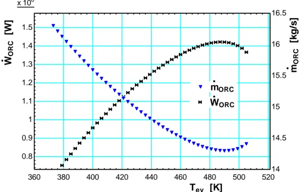
According to the simulation results, a maximum net power output of the system is found at the evaporating temperature of about 214 °C as shown in Figure 6. Indeed, the basic idea behind all the modification to increase the ORC system efficiency (corresponding to the net power output for a constant heat transfer rate of heat source) is to increase the average high temperature (at which heat is transferred to the working fluid from the heat source medium). As can be seen in Figure 6, when evaporating temperature increases the net power output of the system increases until the evaporating temperature reaches about 214 °C. Beyond this temperature the increase of evaporating
10
temperature yields the decrease of turbine inlet specific enthalpy which decrease the shape power output of turbine. While the power input of ORC feed pump always increases in function of evaporating temperature and the electricity consumption for cooling water pump and cooling air fan remain constant (cf. Figure 7). This makes the net power output of the whole system decrease.
Figure 6. Evolution of ORC net power output and necessary mass flow of working fluid when varying evaporating temperature
Figure 7. Evolution of turbine power output and power input of ORC feed pump, water cooling pump and cooling tower fan when varying the evaporating temperature
360 380 400 420 440 460 480 500 520 x 106 0.8 0.9 1 1.1 1.2 1.3 1.4 1.5 14 14.5 15 15.5 16 16.5 Tev [K] W O R C [W ] mO R C [k g /s ] mORC mORC WORC WORC 350 400 450 500 550 x 106 0.6 0.8 1 1.2 1.4 1.6 1.8 x 10³ 0 20 40 60 80 100 120 Tev [K] W t [W ] W p [ W ] Wt Wt Wp Wp Wp,w Wp,w Wfan Wfan W p ,w W fa n
11
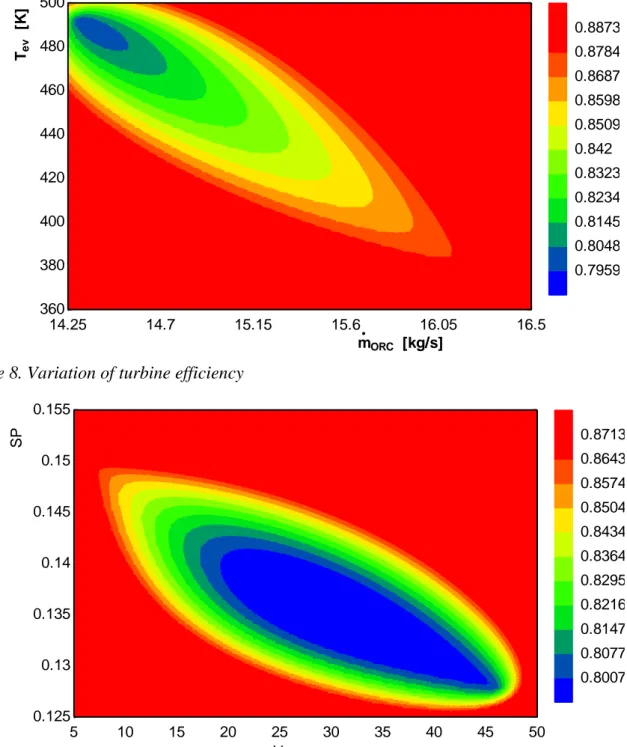
Regarding the turbine isentropic efficiency, it varies from 0.77 to 0.89 and increases with the increase of mass flow rate and the decrease of evaporating temperature of organic working fluid as found in Figure 8. Indeed, the turbine efficiency increases when volume flow ratio decreases and size parameter increases as shown in Figure 9. In practice, a multi-stage axial turbine is often adopted for improving its isentropic efficiency and for avoiding high Mach numbers and large blade height variations across the rotor blade as well as high mechanical stresses [24].
Figure 8. Variation of turbine efficiency
Figure 9. Influence of size parameter and volume flow ratio on turbine efficiency
5. Conclusions and perspectives
The present work evaluates the performance of an ORC system connected to two-phase thermosyphons for recovering the heat of exhaust gas exiting a rolling mill reheating furnace. A component-based model was developed using EES environment to perform the steady-state
14.25 14.7 15.15 15.6 16.05 16.5 360 380 400 420 440 460 480 500 0.8873 0.8784 0.8687 0.8598 0.8509 0.842 0.8323 0.8234 0.8145 0.8048 0.7959 mORC [kg/s] Te v [K ] 5 10 15 20 25 30 35 40 45 50 0.125 0.13 0.135 0.14 0.145 0.15 0.155 0.8713 0.8643 0.8574 0.8504 0.8434 0.8364 0.8295 0.8216 0.8147 0.8077 0.8007 Vr SP
12
modelling as well as the power output optimization of thermosyphons-ORC system. Cyclopentane was preliminarily chosen as ORC working medium due to its good thermo-physical properties at relatively high temperature. Indeed, Cyclopentane is thermally and chemically stable when its bulk temperature is kept below 300 °C. However other organic fluids should be also investigated to bring out the most appropriate working medium for such system. The influence of system operating conditions on turbine isentropic efficiency is also evaluated using an empirical correlation for single-stage axial flow turbine. By optimization process, the maximum net power output of thermosyphons-ORC system is found when the evaporating temperature of Cyclopentane is about of 214 °C. The maximum net power output of the system is about 1.42 MWel corresponding to a thermal efficiency of about 19.1 %.
Acknowledgments
The authors wish to acknowledge the support from the Walloon Public Service for financing the project.
Nomenclature
C capacitance rate, W/K lv h enthalpy of vaporization, J/kg g gravitational acceleration, 9.80665 m/s2 h specific enthalpy, J/(kg.K) k thermal conductivity, W/(m.K)m mass flow rate, kg/s MM molecular mass, g/mol NSPH Net Positive Suction Head, m ODP Ozone Depletion Potential, -
P absolute pressure, Pa
Q heat rate, W
R Thermal resistance, K/W SP size parameter, m
T temperature, °C
V volume flow rate, m3/s
r
V volume flow ratio, -
W power, W
Greek symbols efficiency, -
viscosity, Pa.s
density, kg/m3
Subscripts and superscripts
b normal boiling point c cold or heat sink crit critical
13 in inlet
h hot or heat source lv liquid/vapour
ORC organic Rankine cycle out outlet p pump sat saturation s isentropic t turbine tot total w water
References
[1] Turboden. Turboden Waste to Energy Solutions. 2016.
[2] Booth CM, Swanson LW, Taylor RW. Heat pipes for transferring heat to an organic rankine cycle evaporator. Google Patents; 2011.
[3] Gruss JA, Pardo P. Systeme de recuperation de l'energie de la chaleur de gaz chaud(s) et/ou fumee(s), application a la recuperation de l'energie de fumees encrassantes, en particulier issues de moteurs thermiques. Google Patents; 2016.
[4] Reay DA, Kew PA, McGlen RJ. Heat Pipes Theory, Design and Applications2014.
[5] MacGregor RW, Kew PA, Reay DA. Investigation of low Global Warming Potential working fluids for a closed two-phase thermosyphon. Applied Thermal Engineering. 2013;51(1–2):917-25. [6] ESDU. Heat Pies - Performance of Twophase Closed Thermosyphons. London, U.K.: Engineering Sciences Data Unit; 1981.
[7] Isoppo DF, Borges TPF, Marcia BHM. Development of a detailed thermal model for designing heat pipe heat exchangers. 22nd International Conference on Efficiency, Cost, Optimization Simulation and Environmental Impact of Energy Systems. Foz do Iguaçu, Parana, Brazil2009. [8] Amini A. Heat pipe heat exchangers. 30th HEXAG Meeting. Newcastle, UK2013.
[9] Marcia BHM. Thermosyphon Technology for Industrial Applications. Heat Pipes and Solid Sorption Transformations: CRC Press; 2013. p. 411-64.
[10] Jouhara H. Heat pipe based systems for industrial and renewable energy management. 32nd HEXAG Meeting Newcastle, UK2015.
[11] Badr O, Probert SD, O'Callaghan PW. Selecting a working fluid for a Rankine-cycle engine. Applied Energy. 1985;21(1):1-42.
[12] Commission E. EU legislation to control F-gases. 2013.
[13] Le VL, Kheiri A, Feidt M, Pelloux-Prayer S. Thermodynamic and economic optimizations of a waste heat to power plant driven by a subcritical ORC (Organic Rankine Cycle) using pure or zeotropic working fluid. Energy. 2014;78(0):622-38.
[14] Guillen DP, Zia J. Modifications and optimization of the organic Rankine cycle to improve the recovery of waste heat. Idaho: Idaho National Laboratory; 2013.
[15] Turco PD, Asti A, Greco ASD, Bacci A, Landi G, Seghi G. The ORegen™ Waste Heat Recovery Cycle: Reducing the CO2 Footprint by Means of Overall Cycle Efficiency Improvement. ASME Turbo Expo. Vancouver, British Columbia, Canada: ASME; 2011. p. 547-56.
[16] Copco A. Delivering complete ORC solutions. 2016.
[17] Jeangros G. Waste heat recovery in the cement sector through the organic Rankine cycle. Global Cement Magazine2015. p. 22-4.
[18] Seider WD, Seader JD, Lewin DR, Widagdo S. Product and process design principles: synthesis, analysis, and evaluation: John Wiley, 2010.
14
[19] Astolfi M, Macchi E. Efficiency correlations for axial flow turbines working with non-conventional fluids. 3rd International Seminar on ORC Power Systems. Brussels, Belgium2015. [20] Macchi E, Perdichizzi A. Efficiency Prediction for Axial-Flow Turbines Operating with Nonconventional Fluids. 1981. p. 718-24.
[21] Pidaparti SR, Moisseytsev A, Sienicki JJ, Ranjan D. Counter flow induced draft cooling tower option for supercritical carbon dioxide Brayton cycle. Nuclear Engineering and Design. 2015;295:549-58.
[22] Klein SA. EES: Engineering Equation Solver. Academic P ed. Madison: F-Chart Software; 2013.
[23] Bell IH, Wronski J, Quoilin S, Lemort V. Pure and Pseudo-pure Fluid Thermophysical Property Evaluation and the Open-Source Thermophysical Property Library CoolProp. Industrial & Engineering Chemistry Research. 2014;53(6):2498-508.
[24] Astolfi M, Romano MC, Bombarda P, Macchi E. Binary ORC (Organic Rankine Cycles) power plants for the exploitation of medium–low temperature geothermal sources – Part B: Techno-economic optimization. Energy. 2014;66(0):435-46.

![Figure 2. Thermosyphon and thermal resistances diagram [7]](https://thumb-eu.123doks.com/thumbv2/123doknet/6895923.193795/3.892.147.753.730.973/figure-thermosyphon-thermal-resistances-diagram.webp)
![Figure 3. Schematic of a two-phase closed thermosyphon heat exchanger [8]](https://thumb-eu.123doks.com/thumbv2/123doknet/6895923.193795/4.892.274.621.249.546/figure-schematic-phase-closed-thermosyphon-heat-exchanger.webp)