by
Jérémie LÉGER
THESIS PRESENTED TO ÉCOLE DE TECHNOLOGIE SUPÉRIEURE
IN PARTIAL FULFILLMENT FOR THE DEGREE OF
DOCTOR OF PHILOSOPHY
Ph.D.
MONTREAL, AUGUST 21, 2019
ÉCOLE DE TECHNOLOGIE SUPÉRIEURE
UNIVERSITÉ DU QUÉBEC
BY THE FOLLOWING BOARD OF EXAMINERS
Prof. Daniel R. Rousse, Thesis Supervisor
Département génie mécanique, École de technologie supérieure, Université du Québec
Prof. Danielle Monfet, President of the Board of Examiners
Département génie mécanique, École de technologie supérieure, Université du Québec
Prof. Francois Morency, Member of the jury
Département génie mécanique, École de technologie supérieure, Université du Québec
Prof. Geoffrey Promis, External Independent Examiner
Laboratoire des Technologies Innovantes (LTI - EA 3899), Université de Picardie Jules Verne
THIS THESIS WAS PRESENTED AND DEFENDED
IN THE PRESENCE OF A BOARD OF EXAMINERS AND THE PUBLIC ON JULY 10, 2019
of this project; the t3e group directed by Prof. Daniel Rousse that have given me valuable advice throughout my thesis work and have welcomed me into their group with open arms. I thank the Natural Sciences and Engineering Council of Canada (NSERC) for the funding they have provided me through a PGS-D scholarship. Lastly, I would like to acknowledge Convectair who has not only provided me with extra funding, but also allowed me to perform my experimental investigation at their location and on their cost.
RÉSUMÉ
Les systèmes de chauffage électriques n’ont pas tous une même performance. En effet, un simple changement de la distribution de chaleur peut engendrer une réduction de la consom-mation énergétique tout en maintenant le confort thermique. Dans le cadre de cette thèse, la distribution de chaleur optimale ainsi que la distribution de chaleur de certains systèmes de chauffage électriques sont étudiées et comparées. La première partie de ce travail con-siste en la conception, la construction, la programmation du contrôle et la validation d’une chambre bi-climatique. Cet outil expérimental est essentiel pour comparer des systèmes de chauffage électriques à confort thermique égal. Par la suite, une nouvelle méthode numérique d’investigation de la distribution de chaleur optimale est présentée. Dans cette méthode, le concept du chauffage virtuel est introduit. Les chauffages virtuels sont un ensemble de deux systèmes de chauffage: le premier maximise la perte de chaleur d’une pièce tout en main-tenant le confort thermique à l’intérieur de celle-ci; tandis que le deuxième minimise la perte de chaleur en maintenant lui aussi le même confort thermique. En utilisant la consommation énergétique des chauffages virtuels, trois nouveaux indices de performance sont introduits. Le premier mesure l’efficacité d’une distribution de chaleur. Le deuxième mesure la sensibilité de la consommation énergétique d’une pièce à la distribution de chaleur. Le troisi`ème mesure l’écart entre le meilleur système de chauffage et un vrai système de chauffage. La consom-mation énergétique minimale peut aussi être utilisée comme une mesure de la performance énergétique d’une pièce. La distribution de chaleur maximale est utile pour indiquer la dis-tribution de chaleur à éviter. En approfondissant l’investigation sur la disdis-tribution de chaleur, la chambre bi-climatique est utilisée pour étudier la distribution de température et la consom-mation énergétique de trois systèmes de chauffage électriques. Les résultats expérimentaux montrent que les systèmes de chauffage électriques ne distribuent pas tous la chaleur d’une même façon, et de ce fait, ne consomment pas tous la même quantité d’énergie pour atteindre le même confort thermique. Le convecteur testé a la meilleure performance énergétique quand on le compare à la plinthe électrique et au système de chauffage radiant de cette expérience. Les résultats sur la distribution de chaleur sont aussi comparés avec ceux des chauffages virtuels. Les deux méthodes montrent que chauffer les fenêtres n’est pas efficace. Cette comparaison sert aussi à valider en partie la méthode utilisée pour déterminer les chauffages virtuels. Entre autre, la méthode pour déterminer les chauffages virtuels fût aussi validée par: une compara-ison de valeurs tabulées aux valeurs calculées pour le confort thermique; et une comparacompara-ison de solutions simplifiées calculées à la main aux valeurs calculées par le programme. Dans une dernière étape, les chauffages virtuels sont utilisés pour investiguer comment la distribution de chaleur optimale est influencée par la géométrie et l’isolation d’une pièce. Chaque paramètre investigué est varié individuellement pour quantifier leurs influence sur la consommation én-ergétique, la distribution de chaleur et la sensibilité de la consommation énergétique de la pièce à la distribution de chaleur. Ces résultats montrent que la taille de la fenêtre, l’isolation de la
fenêtre et l’infiltration/exfiltration totale peuvent changer la distribution de chaleur associée au chauffage virtuel minimum. En augmentant chacun de ces trois paramètres, la distribution de chaleur a changé d’un chauffage uniquement au volume d’air à un chauffage qui progressive-ment chauffe davantage le plancher et par la suite le plafond. Les résultats ont aussi montré que la plupart des paramètres géométriques et d’isolation peuvent influencer la sensibilité de la consommation énergétique à la distribution de chaleur. Dans le pire des cas testés, la consom-mation énergétique maximum consomme 86% plus d’énergie que la consomconsom-mation minimum. Le meilleur des cas montre que ce chiffre peut être réduit à 27%. L’isolation de la fenêtre est le paramètre qui a le plus d’influence sur la sensibilité à la distribution de chaleur.
Pour résumer, cette thèse présente une nouvelle façon d’aborder le problème de la distribution de chaleur optimale. Les chauffages virtuels permettent la définition de nouveaux indices de performance qui ont été utiles pour investiguer la performance des systèmes de chauffage et des pièces d’un point de vue de la distribution de chaleur. Par une comparaison expérimentale, il peut être conclu que la distribution de chaleur a une influence sur la consommation énergétique et devrait être considérée dans la conception d’un bâtiment. Le chauffage virtuel est sans doute un outil qui servira à mieux comprendre comment atteindre des distributions de chaleur optimales.
Mots-clés: vote moyen prédit, confort thermique, chauffage optimale, chauffage virtuel, effi-cacité énergétique, chauffage électrique
ABSTRACT
Electric heating systems do not to perform all equally in terms of energy consumption. In fact, by changing the heat distribution, thermal comfort can be achieved with less energy consumed. In this thesis, the optimal heat distributions and the heat distributions of electric heating devices are investigated and compared. In the first part of this work, the design, construction, control and validation of a climatic chamber is presented. This experimental tool is essential to com-pare electric heaters at equal thermal comfort. In what follows, a novel method of investigating the optimal heat distribution numerically is presented. In this method, the concept of virtual heaters is introduced. Virtual heaters are a set of two heat distributions: one that maximizes the total heat loss of a room, while maintaining thermal comfort inside this room; whereas the other minimizes the total heat loss, while still maintaining the same thermal comfort. Using the virtual heaters energy consumption, three new performance indices are introduced. The first performance index measures the effectiveness of a heater to distribute heat; the second measure the significance of the heat distribution inside a room from an energy consumption standpoint; the third measure how the diference in energy from the virtual heater and a real heater. The minimum energy loss can also be used as a measure of the room’s energy efficiency, while the maximum virtual heater gives an indication on heat distributions to avoid. Expanding the investigation on heat distribution, the bi-climatic chamber tool is then used to investigate the temperature distribution and energy consumption of three electric heating systems. The results from this experiment show that not all electric heating systems distribute heat in the same way, and from this fact, they do not all have the same energy consumption when providing similar thermal comfort. The convection heater experimentally tested here outperformed the radiant heater and baseboard heater. The experimental heat distribution results are also compared with those of the virtual heater. Both methods agree that avoiding to heating the windows is most efficient. This comparison also serves, in part, as a validation of the method used to find virtual heaters. Other validations for key calculations in the virtual heater models include: comparing tabulated results to calculated results for the thermal comfort model; and comparing simplified solutions calculated analytically by hand to the one calculated by the model for the heat trans-fer model. Finally, the virtual heaters are used to investigate how optimal heat distributions change with respect to the room geometry and insulation parameters. Investigated parameters were varied individually to quantify their effects on the energy consumption, the heat distribu-tion, and the sensibility of the room heat loss to heat distribution. Interestingly, the window size, the window insulation level and the air infiltration/exfiltration rate can drastically change the minimum energy consumption heat distribution. It was observed that when increasing each of these three parameters, optimal heat distribution changed from heating the air volume to floor heating. The results also showed that most geometric and insulation parameters can influence the sensibility of heat loss to heat distribution. The percentage increase of energy consumption for the maximum virtual heater when compared to the minimum virtual heater
was observed to range from 27.4% to 86.0% for the tested cases. The window insulation was found to be the predominant factor influencing the sensibility of heat loss. In summary, this thesis presents a new concept termed virtual heater that is useful in the investigation of indoor heat distribution. Using the virtual heaters and their associated performance indices, the opti-mal heat distributions for different room geometry and insulation topologies, and the efficiency of some electric heating devices were assessed. Heat distribution can have a significant effect on the energy consumption of heaters and should be considered in building design. Virtual heaters are tools that can undoubtedly help to find more general understandings of optimal indoor heat distribution.
Keywords: predicted mean vote, thermal comfort, optimal heating, virtual heaters, electric heating, energy efficiency
INTRODUCTION . . . 1
CHAPTER 1 LITERATURE REVIEW . . . 5
1.1 Thermal comfort . . . 5
1.1.1 Fanger’s PMV . . . 7
1.1.2 Adaptive approach . . . 10
1.1.3 Hybrid models . . . 12
1.2 Climatic Chambers . . . 13
1.3 Energy efficiency, heat distribution and thermal comfort . . . 15
1.3.1 Thermostats and control strategies . . . 16
1.3.2 Diffusor heat distribution . . . 19
1.3.2.1 Heat diffusors . . . 19
1.3.2.2 Experimental investigations . . . 21
1.3.2.3 Numerical models of room heat transfer . . . 23
1.3.2.4 Numerical results of room heat transfer . . . 26
1.4 Effects of room geometry and insulation on heating . . . 30
1.4.1 Room geometry . . . 30
1.4.2 Room insulation . . . 32
1.5 Conclusions . . . 33
CHAPTER 2 THE CLIMATIC CHAMBER . . . 35
2.1 Description of the basic chamber . . . 35
2.2 The chamber’s controller . . . 40
2.3 Measurement equipments . . . 43
2.4 Bi-climatic chamber improvements . . . 49
2.5 A second climatic chamber . . . 52
2.6 Conclusions . . . 53
CHAPTER 3 EXPERIMENTAL INVESTIGATION . . . 55
3.1 Description of experiment . . . 56
3.2 Error analysis . . . 57
3.3 Results . . . 61
3.4 Comparing electric heaters . . . 69
3.5 Conclusions . . . 74
CHAPTER 4 VIRTUAL HEATERS . . . 75
4.1 Usefulness of the virtual heaters . . . 76
4.2 A model for solving virtual heaters . . . 79
4.2.1 Total heat loss . . . 81
4.2.3 Thermal comfort . . . 89
4.2.4 Solving the optimization problem . . . 90
4.2.4.1 Gradient of the heat loss and heat distribution . . . 91
4.2.4.2 Gradient of thermal comfort . . . 91
4.2.4.3 Choice of an optimization algorithm . . . 94
4.3 Choice of a simplified model . . . 98
4.4 Model validation . . . 99
4.5 Case study: the Klimat test room . . . .101
4.5.1 Results without temperature limits . . . .103
4.5.2 Results with limited temperatures . . . .105
4.5.3 Discussion . . . .112
4.5.3.1 Effectiveness, sensibility and power savings . . . .112
4.5.3.2 Heat transfer model limitations . . . .113
4.5.3.3 PMV model range limitation . . . .114
4.5.3.4 Adequate compromise . . . .115
4.5.3.5 Upcoming work . . . .115
4.6 Conclusions . . . .115
CHAPTER 5 THE EFFECT OF GEOMETRY AND INSULATION ON OPTIMAL HEATING . . . .119
5.1 Parametric analysis . . . .119
5.1.1 Effect of geometry . . . .121
5.1.2 Effect thermal parameters . . . .121
5.2 Results . . . .123
5.2.1 Effect of geometry . . . .126
5.2.1.1 Window to wall ratio . . . .126
5.2.1.2 Room depth . . . .131
5.2.1.3 Room height . . . .135
5.2.2 Effect of changing R-value . . . .139
5.2.2.1 Wall 1 insulation . . . .140
5.2.2.2 Wall 2, 3 and 4 insulation . . . .142
5.2.2.3 Floor insulation . . . .145
5.2.2.4 Ceiling insulation . . . .146
5.2.2.5 Number of window panes . . . .149
5.2.2.6 Air exchange rate . . . .153
5.2.2.7 Outdoor temperature . . . .158
5.3 Effects of geometry and thermal parameters . . . .160
5.4 Conclusions . . . .164
CONCLUSION AND RECOMMENDATIONS . . . .167
APPENDIX I CALIBRATION OF THERMOCOUPLE WIRE . . . .175
APPENDIX III CALCULATING THE VIEW FACTORS . . . .187
APPENDIX IV MATLAB FUNCTIONS . . . .193
APPENDIX V ARTICLES IN CONFERENCES . . . .271
APPENDIX VI ARTICLES IN JOURNALS . . . .273
Table 1.1 Thermal comfort scales . . . 6
Table 1.2 Adaptive relations . . . 12
Table 3.1 Accuracy of measurements . . . 58
Table 3.2 Number of samples for each tested temperature . . . 58
Table 4.1 Boundary conditions for temperature distributions used to validate the model . . . .100
Table 4.2 Comparison of modeled vs measured total average power consumption . . . .100
Table 4.3 Wall conductivity, thermal resistance and thickness . . . .102
Table 4.4 Simulation results . . . .105
Table 4.5 mVH and MVH average, minimum and maximum temperatures predictions for the climate chamber [◦C] . . . .109
Table 5.1 Test cases for the effect of geometry . . . .122
Table 5.2 Test cases for the effect of thermal parameters . . . .123
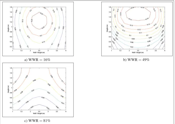
Table 5.3 mVH heat distribution per heated room elements as function of WWR . . . .127
Table 5.4 mVH heat distribution per heated room element as a function of air exchange rate . . . .155
Figure 2.1 Bi-climatic chamber plan view. Source: C828-13 (CSA, 2013). . . 36
Figure 2.2 Bi-climatic chamber elevation view. Source: C828-13 (CSA, 2013) . . . 37
Figure 2.3 Bi-climatic chamber windows on wall 1 . . . 38
Figure 2.4 Bi-climatic chamber windows on wall 2 . . . 38
Figure 2.5 Bi-climatic chamber door on wall 4. . . 39
Figure 2.6 Heating and cooling components of the Klimat . . . 39
Figure 2.7 Thermocouples on wall with the heating system . . . 45
Figure 2.8 Thermocouples on walls with no heating system . . . 46
Figure 2.9 Thermocouples on ceiling and floor . . . 46
Figure 2.10 Thermocouples hanging from the ceiling . . . 47
Figure 2.11 Comfort sense probes. Source: Dantec.com . . . 48
Figure 2.12 Sketch of the modular cold room facing wall section . . . 51
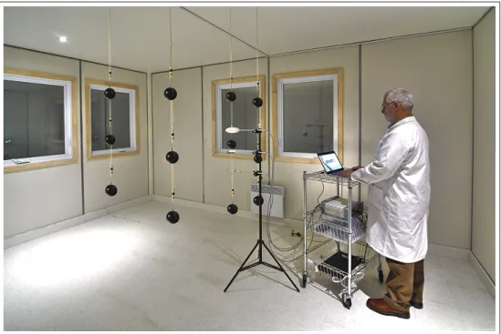
Figure 2.13 Picture of the finished bi-climatic chamber (Klimat) and visualization chamber (Vortex) . . . 52
Figure 2.14 Picture of the test room in the bi-climatic chamber . . . 53
Figure 2.15 Picture of the finished fluid mechanics chamber : The VORTEX . . . 54
Figure 3.1 Normalized temperature errors (95% confidence) . . . 59
Figure 3.2 Normalized error of draft rate and power (left axes) along with PMV error (95% confidence) (right axes) . . . 60
Figure 3.3 Comparison of power consumptions . . . 62
Figure 3.4 Normalized air temperatures overall . . . 64
Figure 3.6 Normalized air temperatures on mid plane . . . 66
Figure 3.7 Mean radiant temperatures on mid plane . . . 67
Figure 3.8 Cold room exposed surfaces normalized temperatures . . . 68
Figure 3.9 Warm rooms exposed surfaces normalized temperatures . . . 69
Figure 3.10 Wall temperatures above heater . . . 70
Figure 3.11 Average relative humidity at the geometric center of the test room . . . 71
Figure 3.12 Average air velocity at the geometric center of the test room . . . 71
Figure 3.13 Average thermal comfort at the geometric center of the test room . . . 72
Figure 3.14 Thermal plume of the tested convector . . . 73
Figure 4.1 Schematic representation of the energy balance on the complete enclosure considered in this study . . . 82
Figure 4.2 Energy balance on a control-volume defined by a surface element of surface area L× L and thickness t. ... 85
Figure 4.3 Two elemental sub-surfaces on the right wall and related geometrical parameters . . . 86
Figure 4.4 Test room top view. . . .102
Figure 4.5 Floor temperatures for mVH (no temperature limit) . . . .104
Figure 4.6 Top view of the temperature distribution on the floor with the mVH, [◦] . . . .107
Figure 4.7 Temperature distribution on the windows of wall 1 for the MVH seen from the outside, [◦] . . . .108
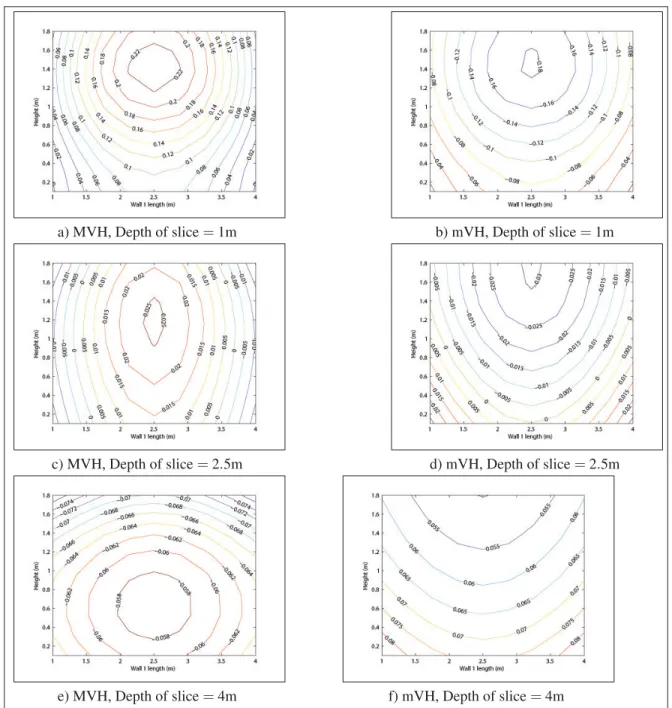
Figure 4.8 Temperatures distributions on wall 1 [◦C]:(a) mVH; (b) MVH . . . .110
Figure 4.9 Temperature distributions on the floor [◦C]: (a) mVH; (b) MVH . . . .110
Figure 4.10 Thermal comfort distributions of three vertical occupied sections of the comfort volume, [PMV]: (a) mVH and x=1; (b) MVH and x=1;(c) mVH and x=2.125; (d) MVH and x=2.125;(e) mVH and x=4; (f) MVH and x=4; . . . .111
Figure 5.2 Elevation view of the tested room . . . .121 Figure 5.3 Wall 1 temperatures for the base case . . . .124 Figure 5.4 Thermal comfort (PMV ) at different depth values for the base case
mVH and MVH . . . .125 Figure 5.5 Room heat distribution sensibility (RHDS) as a function of window
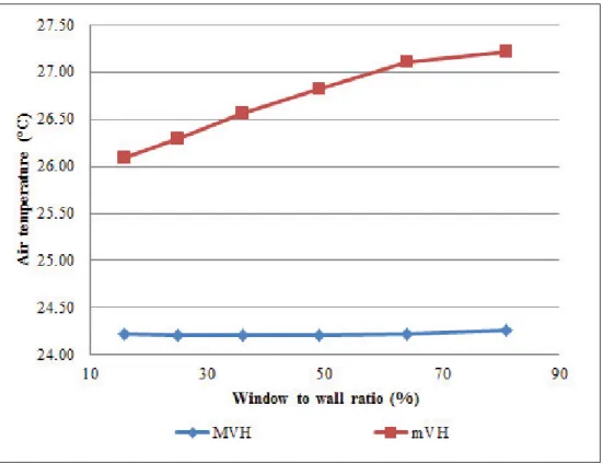
to wall ratio. . . .126 Figure 5.6 MVH and mVH air temperatures as a function of window to wall
ratio . . . .128 Figure 5.7 Wall 1 temperatures for different window to wall ratio and for the
MVH . . . .129 Figure 5.8 Thermal comfort at 1m offset from wall 1 for different window to
wall ratio and for the MVH. . . .130 Figure 5.9 Floor temperatures for different window to wall ratio and for the
mVH . . . .130 Figure 5.10 Thermal comfort at the center of the room for a WWR=81% . . . .131 Figure 5.11 Room heat distribution sensibility (RHDS) and heat consumption
as a function of room depth . . . .132 Figure 5.12 MVH and mVH air temperature as a function of room depth . . . .133 Figure 5.13 Wall 1 temperatures for three room depths, 7.5, 10, and 15 m, and
for the MVH . . . .134 Figure 5.14 Thermal comfort (PMV ) at 1m offset from wall 1 and for different
depths of 7.5 and 10 m . . . .134 Figure 5.15 Room heat distribution sensibility (RHDS) and heater consumption
as a function of the room height . . . .135 Figure 5.16 Room air temperatures for the mVH and MVH . . . .136 Figure 5.17 Wall 1 temperatures for the MVH and for different heights . . . .137 Figure 5.18 Thermal comfort (PMV ) at 1m offset from wall 1 for MVH and for
different room heights of 3 and 6 m . . . .138 Figure 5.19 Floor temperature for the mVH with a room height of 6m . . . .138
Figure 5.20 Thermal comfort volume slice at the center of the room (parallel to
wall 1) and for the mVH. . . .139 Figure 5.21 RHDS and energy consumption of virtual heaters as a function of
wall 1 insulation . . . .140 Figure 5.22 Room air temperatures for the mVH and MVH as a function of
wall 1 insulation . . . .141 Figure 5.23 Wall 1 temperatures for the MVH and for different wall 1
insulations . . . .142 Figure 5.24 RHDS and energy consumption of virtual heaters as a function of
walls 2 to 4 insulations . . . .143 Figure 5.25 Room air temperatures for the mVH and MVH as a function of
walls 2 to 4 insulations . . . .144 Figure 5.26 Wall 1 temperatures for the MVH and for different insulation of
wall 2 to 4 insulations . . . .145 Figure 5.27 RHDS and energy consumption of virtual heaters as a function of
floor insulation . . . .146 Figure 5.28 Room air temperatures for the mVH and MVH as a function of
floor insulation . . . .147 Figure 5.29 Wall 1 temperatures for the MVH and for different floor insulations
(Rf loor) . . . .147
Figure 5.30 RHDS and energy consumption of virtual heaters as a function of
ceiling insulation . . . .148 Figure 5.31 Room air temperatures for the mVH and MVH as a function of
ceiling insulation . . . .149 Figure 5.32 Wall 1 temperatures for the MVH and for different ceiling
insulations . . . .150 Figure 5.33 RHDS and energy consumption of virtual heaters as a function of
window thermal resistance . . . .151 Figure 5.34 Room air temperatures for the mVH and MVH as a function of
Figure 5.35 Wall 1 temperatures for the MVH and for different window thermal
resistance . . . .152 Figure 5.36 RHDS and energy consumption of virtual heaters as a function of
the air exchange rate . . . .153 Figure 5.37 Room air temperatures for the mVH and MVH as a function of the
air exchange rate . . . .154 Figure 5.38 Wall 1 temperatures for the MVH and for different air exchange
rates . . . .155 Figure 5.39 Floor temperatures for the mVH and for different air exchange
rates . . . .156 Figure 5.40 Ceiling temperatures for the mVH at an air exchange rate of
0.7ACH...157 Figure 5.41 Thermal comfort for the mVH at 0.7ACH and for different section
cuts parallel to wall 1 where x is the distance from wall 1. . . .157 Figure 5.42 RHDS and energy consumption of virtual heaters as a function of
the outdoor temperature . . . .158 Figure 5.43 Room air temperatures for the mVH and MVH as a function of the
outdoor temperature . . . .159 Figure 5.44 Wall 1 temperatures for the MVH and for different outdoor air
A Surface area, [m2]
C Conductance matrix, [W/K]
cp Heat capacity, [kJ/kg]
E Energy, [J]
˙
E Energy rate (heat rate),[W]
err Error, [-]
fcl Clothing factor, [-]
Fi j View factor of surface i with respect to surface j, [-]
h Convection heat transfer coefficient, [W/m2K]
I Clothing level, [m2K/W]
J Radiosity, [W/m2]
k Conductivity, [W/Km]
m Mass, [kg]
˙
m Mass flow rate, [kg/s]
N Number of sub-surfaces, [-]
NDRE Normalized draft rate error, [-]
NP Normalized power, [-]
P Pressure, [Pa]
p Percentage of cycle, [%]
PMV Predicted mean vote, [PMV scale vote]
PPD Predicted percentage of dissatisfaction, [%] ˙
Q Heat distribution, [W]
R Radiation matrix, [W/K]
RHDS Room heat distribution sensitivity, [-]
T Temperature, [◦C]
t Time, [s]
˙
V Volumetric flow rate, [m3/h]
v Velocity or air draft rate, [m/s]
Greek letters α , Damping factor, [-] ε , Surface emissivity, [-] εAH , Heater effectivness, [-] σ , Stefan-Boltzmann constant, 5.67 × 10⁸[W/m2K4] Θ , Normalized temperature, [-] Subscripts
2D Pertains to two dimensions
50Pa At 50Pa of pressure
adj Adjusted AH Actual heater air Air av Average bal Balance cl Clothing
cold Cold room
cond By conduction
conv By convection
crawl Crawl space
cycle Pertains to a heater cycle
d Desired
diff Water vapour diffusion
dr Dry respiration
du Dubois
ELA Equivalent leakage area
eq Equivalent
ex Air exchange (infiltration/exfiltration)
gain Source in a volume
globe Black globe
ih Internal heat
in Inside of enclosure
loss Heat loss (sink in a volume)
lr Latent respiration
m Measured
met Metabolic
mrad Mean radiant
mVH Minimum virtual heater
MVH Maximum virtual heater
n Neutral
op Operative
out Outside of enclosure
rad Radiation
s Wall surface
sk Skin
Stan Standard
sw Sweat evaporation
TC Thermal comfort constraints
test Test room
tot Total
var Variation
vh Virtual heater
w Water vapour
warm Warm room
alone represents 62% of the residential energy use (Canada, 2016). Nearly 25% of households are heated by electric systems (Snider, 2006). Electric heating thus represents an important part of the total Canadian energy use. As Canada tries to reach its greenhouse gas emission targets, efficiencies in the household heating sector could significantly contribute to these reductions, especially in regions of the country where electricity is produced with fossil fuels. Hence, in this thesis, the optimal energy consumption of electric heating systems to achieve thermal comfort is investigated.
For space heaters, design objectives can be interpreted in two ways: first, a minimum indoor temperature might be required; second, the heating system should provide thermal comfort to the occupant of the building. For example, an absent house owner will heat his house to a minimum temperature to prevent water pipes from freezing and bursting. On the other hand, when the house is occupied, the heating system should provide thermal comfort within the occupied indoor space. This thesis will focus on the system objective of thermal comfort. Thermal comfort being defined as the occupant’s subjective response related to the satisfaction of a thermal environment. Apart from quality of life, thermal comfort has also been linked to work productivity (Mohamed & Srinavin, 2005) and sleep quality (Bischof et al., 1993). Thought there are many types of heating systems that may achieve thermal comfort, the par-ticularity of electric heating systems is that they convert 100% of their electrical power to heat. Gains in efficiency for these systems are thus limited to how the produced heat is used within the indoor space to achieve thermal comfort. Particularly, this may pertain to the heat distri-bution of the system. Moreover, electric heaters are good for investigating heat distridistri-bution experimentally as they convert power to useful heat with the same efficiency. The objectives of this thesis are then further narrowed to the following two research questions:
- Do all electric heating systems consume the same amount of energy while providing an equal thermal comfort?
- What characterises an energy optimal indoor heat distribution constrained by thermal com-fort?
To answer these questions, both a numerical and an experimental approach are utilized. The experimental investigation aims at answering the first research question. Using a bi-climatic chamber, three electric heaters are compared on the basis of their energy consumption and their heat distribution.
The second research objective will be answered through a numerical investigation. From the formulation of the second research question, thermal comfort is interpreted as a constraint to satisfy, while energy consumption an objective to minimize. This formulation of the problem highlights how thermal comfort is interpreted in the context of indoor space heating for this thesis. Others have interpreted thermal comfort as being a secondary objective two optimize. In this way, optimal solutions compromise on thermal comfort to achieve energy efficiency. It is argued in this thesis that the constrained approach is more accurate than the secondary objective approach since occupants will eventually adjust the heating system to achieve thermal comfort. Furthermore, the constrained approach gives rise to a new method of investigating heat distribution called virtual heaters as defined in Chapter 4.
Virtual heaters are a set of two heat distributions that satisfy the indoor thermal comfort con-straint: the minimum virtual heater minimize the total heat loss; while the maximum virtual heater maximizes the same. From the virtual heaters, new performance indices for charac-terizing the optimal heat distribution of heating systems and rooms are introduced. These performance indices along with the virtual heaters are the primary tools used in this work to characterize optimal heat distribution.
The first index measures the heat distribution performance of heating systems. Prior to the definition of this new performance index, the primary method for comparing the heat distri-bution performance was to compare heating systems with themselves. As it will be argued in this thesis, this approach can be limiting as there is no way to know if the best observed heat distribution can be improved. By using the minimum virtual heater in the performance index, this ambiguity is no longer present as the minimum consuming solution is known. The heat distribution effectiveness is also used in the context of this thesis to assess the heat distribution performance of the experimentally tested heaters.
The second performance index, room heat distribution sensibility (RHDS), measures the im-portance of heat distribution for energy efficiency in a single room. Though it can be know from experience that some rooms are prone to be sensible to heat distribution, this perfor-mance index measures the sensibility based on the virtual heaters. This becomes particularly important when comparing the optimal heat distributions of different rooms.
Since virtual heaters are room dependent, a parametric analysis of the room geometry and insulation parameters was used to investigate the optimal heat distribution characteristics of different rooms. Using the RHDS, the importance of heat distribution is assessed. The min-imum virtual heater gives the desired characteristic of heat distribution, while the maxmin-imum virtual heater gives the heat distribution characteristics to avoid. Using this analysis, the second research question is answered.
This thesis is divided into 5 chapters. In the first chapter, a literature review discusses back-ground information and recent works on thermal comfort, investigations of heat distribution and tools, and the effects of geometry and insulation on the total heat loss. This is followed by two chapters introducing the tools used in this work to investigate thermal comfort and heat distribution. In Chapter 2, a bi-climatic chamber is discussed for use with experimental inves-tigations. In Chapter 4, the virtual heaters are introduced along with their solution methods. In
what follows, an experimental investigation of the energy consumption of three electric heaters at equal thermal comfort is presented and the first research question is answered. The second research question is more thoroughly answered in Chapter 5. In this chapter, a comparison of the heat distributions for different room geometries and insulations is provided. Conclusions and future perspectives are then given in the final chapter.
An overview of the topics relative to optimal heat distribution is now presented. For optimal heating, thermal comfort is seen as a constraint to be achieved while energy consumption, a objective to minimize. It is therefore important to properly define thermal comfort and hence, a discussion of thermal comfort and its models is presented in Section 1.1.
Heat distribution has been studied using either numerical simulation or experiments. This thesis uses both. In Section 1.2, existing climate chambers are discussed as this is an important experimental tool. Thermostat control strategies are then discussed in Section 1.3.1. Heating methods are covered in Section 1.3.2.1. and experimental investigations on heat distribution using these systems are discussed in Section 1.3.2.2.
Investigating heat distribution using simulations and numerical models is reviewed in Sec-tion 1.3.2.3. The results of numerical models to investigate heat distribuSec-tion are then discussed in Section 1.3.2.4.
To expand on the concept of optimal heating, the effects of room geometry and insulation are reviewed in Section 1.4.
The following sections highlight key contributions in each distinct topics for which this thesis will cover or improve upon. A summary of the relevant literature is presented in Section 1.5.
1.1 Thermal comfort
Thermal comfort is a central component in understanding how indoor heating and cooling systems perform. The Merriam Webster dictionary defines comfort as "a state or situation in which you are relaxed and do not have any physical unpleasant feeling caused by pain, heat, cold, etc." (Merriam-Webster, 2015). ASHRAE defines thermal comfort as "the condition of mind in which satisfaction is expressed with the thermal environment" (ASHRAE-55, 2013).
Based on these definitions, it is clear that thermal comfort is an interdisciplinary concept. The state of mind being related to psychology, the physical stimuli relating to physiology, and the science of controlling a thermal environment has historically been the work of HVAC engineers and practitioners.
To control a state of comfort, one must first be able to measure comfort. In the 1930’s, Bedford (Bedford, 1936) was the first to proposed a thermal comfort scale, nowadays known as the Bedford scale. His experiment was simply to ask occupants what level of comfort they felt in a room, from much too cold on the lower end of the scale to much too hot on the upper end of the scale. This seems quite obvious, the best way to measure thermal comfort is simply to ask occupants what level of comfort they feel. Other scales have since been proposed, the differences being the words used to describe thermal comfort associated with a number on the scale. Each thermal comfort scale thus covers a limited range of responses. Table 1.1 shows a comparison of different thermal comfort scales.
Table 1.1 Thermal comfort scales
PMV (Fanger, 1970) Bedford (Bedford, 1936) SHASE (Rijal et al., 2015)
hot 3 much to warm 7 very hot 3
warm 2 too warm 6 hot 2
slightly warm 1 comfortably warm 5 slightly hot 1
neutral 0 neither cool nor warm, hence comfortable 4
neutral
(neither cold nor hot) 0 slightly cool −1 comfortably cool 3 slightly cold -1
cool −2 too cold 2 cold -2
cold −3 much to cold 1 very cold -3
For building design purposes, it is also important to know what affects thermal comfort. A number of studies have been published on this topic and are carefully reviewed in (Djongyang
et al., 2010; Mohammad et al., 2013). From these studies, two points of views can be
identi-fied: On one hand, the "engineer’s" point of view sees the problem as a heat transfer problem between the occupant and his environment; while on the other hand, the "architect" point of view sees the problem as the human adaptation to his environment. In fact, both points of views
are correct and each has their own contributions to thermal comfort. Yau (Yau & Chew, 2014) provides a good review of both points of view.
1.1.1 Fanger’s PMV
A number of heat balance models have been proposed in the literature (Fanger, 1970; Fi-ala & Havenith, 2015a; FiFi-ala et al., 2010; Stolwijk & Hardy, 1977; Nishi & Gagge, 1977; Wissler, 1961; Werner, 1990; Fiala et al., 2007, 2012). In most cases, the human body is dis-cretized in a number of concentric cylinders and a detailed heat transfer analysis is performed. In an effort to dynamically simulate thermal comfort, Fiala proposed numerous detailed adap-tive heat transfer models of the human body (Fiala & Havenith, 2015b; Fiala et al., 2010, 2012, 2007). A thermoregulation control model was developed by Stolwijk (Stolwijk & Hardy, 1977). Amongst these heat balance models, Fanger’s thermal balance model (Fanger, 1970), similar to Wissler’s model (Wissler, 1961), stands out as a practical model for use in evalu-ating thermal comfort. The standard effective temperature (SET) (Gagge & Gonzalez, 1972; Nishi & Gagge, 1977; Gagge et al., 1986) has also been widely used. Fanger proposed a thermal comfort index based on observations that led him to formulate the following three requirements needed to achieve thermal comfort:
1. The body is in heat balance, i.e., the internal heat produced by the occupant is equal to the heat removed from the body by the surrounding environment.
2. The sweat rate and skin temperature affecting the heat balance are within certain limits. 3. No local discomfort exists, i.e. radiation asymmetry, cold draught, and air temperature
From the first statement, Fanger developed his heat balance model (Fanger, 1970): ˙
Econd,cl= ˙Egain,ih− ˙Eloss,diff,sk− ˙Eloss,sw,sk− ˙Eloss,lr,sk− ˙Eloss,dr,sk (1.1) ˙
Econd,cl= ˙Eloss,rad+ ˙Eloss,conv (1.2) ˙
Ebal= ˙Egain,ih− ˙Eloss,diff,sk− ˙Eloss,sw,sk− ˙Eloss,lr,sk− ˙Eloss,dr,sk− ˙Eloss,rad− ˙Eloss,conv (1.3)
where each term is in units of watts (W ), ˙Egain,ihis the internal heat production, ˙Eloss,diff,skis the
heat loss by water vapour diffusion through the skin, ˙Eloss,sw,sk is the heat loss by skin surface sweat evaporation, ˙Eloss,lr,sk is the latent respiration heat loss, ˙Eloss,dr,sk is the dry respiration
heat loss, ˙Eloss,radis the heat loss by radiation, ˙Eloss,conv is the heat loss by convection, ˙Econd,cl
is the conduction through the clothing.
Equations for the skin temperature Tskand sweat heat loss ˙Eloss,sw,skwere then obtained through an experimental study of thermal comfort performed in a climatic chamber on college age students wearing standardised clothing and performing standardised activities while being ex-posed to a steady state condition for a period of 3 hours. From the double heat balance equa-tions, Eq. 1.1 and 1.2, and experimental data on thermal comfort, Fanger then derived his thermal comfort index (Fanger, 1970):
PMV = ⎛ ⎜ ⎜ ⎝0.303e ⎛ ⎝−0.036E˙gain,ih Adu ⎞ ⎠ + 0.028 ⎞ ⎟ ⎟ ⎠E˙bal (1.4)
where Adu, the DuBois surface area, is the effective heat exchange surface area of the body.
The PMV , which stands for predicted mean vote, is the comfort index related to the PMV scale shown in Table 1.1. ˙Ebal is the heat balance, which should be zero when the body is in thermal
As a second method of considering thermal comfort, Fanger proposed a relation between the predicted percentage of dissatisfaction (PPD) and the PMV index:
PPD= 100 − 95e(−0.03353PMV4−0.2179PMV2) (1.5)
The PPD estimates the percentage of occupants that will be dissatisfied with the thermal envi-ronment. It is important to note that there will always be some level of dissatisfaction, therefore the best that can be achieved is to minimize the percentage of dissatisfaction. Using Fanger’s
PPD equation, Eq. (1.5), with 100 and 95 as embedded constants, the minimum PPD is 5%
when PMV = 0.
The PMV and thus the PPD depends on six parameters: the air temperature Tair, mean radiant
temperature Tmrad, humidity as represented by the water vapour pressure Pwand air velocity v
are the four environmental parameters; and, the clothing level Icl, and metabolic rate ˙Emet are
the two occupant parameters. Other factors such as radiation asymmetry could also be consid-ered for thermally asymmetric environments (Halawa et al., 2014), but will not be considconsid-ered in the analysis of this thesis. A sensitivity analysis performed by Holz et al. (Holz et al., 1997) showed that the most sensitive parameters of PMV are the clothing level, metabolic rate, air temperature and mean radiant temperature. The air velocity and humidity have less of an impact on PMV (Holz et al., 1997); however, humid and windy environments make thermal comfort more sensitive to changes in temperature.
Fanger’s thermal comfort is not without limitations, there have been numerous validations of the thermal comfort model. In some cases, the model predicted a level of comfort well within a certain range (Humphreys & Nicol, 2002; Parsons, 2002; Buratti & Paola, 2009). In other cases, the actual mean vote (AMV ) was significantly different from the PMV (Foun-tain et al., 1996; Doherty & Arens, 1988). Given that, the PMV thermal comfort index is inherently static, it does not perform well when occupants are used to variable thermal condi-tions. This is the case of naturally ventilated buildings, where the PMV fails to predict comfort (de Dear & Brager, 2001; de Dear, 2004). Naturally ventilated buildings provide less
consis-tent temperatures than HVAC controlled buildings in which PMV predicts comfort well. The comfort temperature range for naturally ventilated buildings given by adaptive models is gen-erally broader than the range predicted by PMV . The broader range could be used to lower energy consumption as the comfort temperature can be set to a higher or lower setpoint (Holz
et al., 1997; Yang et al., 2014; Kwong et al., 2014). Despite its difficulties in predicting thermal
comfort in naturally ventilated buildings, PMV is still the most widely used thermal comfort index (Van Hoof, 2008). In fact, standards such as ASHRAE 55 (ASHRAE-55, 2013) and ISO 7730 (ISO-7730, 2005) have adopted PMV as the primary method to predict thermal com-fort; whereas an adaptive model has been adopted by ASHRAE only for naturally ventilated buildings under specific conditions (ASHRAE-55, 2013).
1.1.2 Adaptive approach
Adaptive models are useful in predicting thermal comfort in situations where Fanger’s model is not compatible with the AMV (de Dear & Brager, 1998), as is the case for naturally venti-lated buildings. They have generally tried to predict thermal comfort in changing conditions, whereas PMV is more of a static index. The premise of adaptive models is that occupants will adapt to their thermal environment. As such, they will find ways to achieve thermal comfort when the opportunity is provided (Humphreys et al., 2015). The adaptive models also state that past thermal history will influence the thermal expectation and thus the thermal comfort (de Dear & Brager, 1998). The adaptation process can by subdivided into three major cate-gories: physiological, psychological and behavioural adaptations (Nicol et al., 2012). Physio-logical adaptation is how the body will adapt using its own mechanism of thermal regulation e.g. vasoconstriction and perspiration. Psychological adaptation pertains to the perception of thermal comfort based on past experiences. Behavioural adaptations are actions taken by a person to achieve thermal comfort. This may include personal, technological and even cultural adjustments. Some examples of these adjustments include changing one’s clothing (personal), adjusting the thermostat (technological) or even taking a nap during warm periods of the day (cultural).
Adaptation to the outdoor temperature has received considerable attention (Chun et al., 2008; Bouden & Ghrab, 2005; Luo et al., 2016; Toe & Kubota, 2013; Humphreys, 1978; ASHRAE-55, 2013; BS-EN-15251, 2007). Relations between thermal history and indoor thermal comfort where investigated in Seoul Korea and Yokahama Japan by Chun (Chun et al., 2008). Results showed that the thermal conditions experienced by the subjects during the 24 hour prior to the test in the climatic chamber did influence their thermal perception. In Tunisia, climatic chamber experiments were also conducted (Bouden & Ghrab, 2005). Correlations were given for the effective temperature and globe temperature to comfort votes and also between clothing levels and outdoor temperature. Concerning the mean outdoor temperature, a recent study conducted in China concluded that occupants that moved from northern China to southern China or vice versa, had lower comfort expectations, i.e. a wider range of acceptability, than occupants who had stayed in their respective regions (Luo et al., 2016). Adaptation to mean outdoor temperature were also investigated for hot and humid climatic regions (Toe & Kubota, 2013). Using the ASHRAE RP-884 database, three correlations differing from those used in standard ASHRAE 55 were found. Correlations to outdoor temperatures are also used in some standards such as ASHRAE 55 (ASHRAE-55, 2013; BS-EN-15251, 2007).
Other studies focused on the adaptation of clothing (Parsons, 2010; Bouden & Ghrab, 2005; Linden et al., 2008; de Dear & Brager, 1998; Mui & Chan, 2003; Wray, 1980; Parsons, 2014), air velocity (de Dear & Brager, 1998; Mui & Chan, 2003) and gender differences (Amai et al., 2007). It is apparent from these studies and correlations, that adaptive comfort is difficult to measure and that it heavily relies on the collection and correlation of experimental data. Table 1.2 summarizes some adaptive relations found in literature.
In Table 1.2, Topis the operative temperature, Toutis the outdoor temperature, Tglobeis the globe
temperature, Tcomf is the comfort temperature, Tn is the neutral temperature, I is the clothing
level, v is the air velocity and ˙Emet,avis the average metabolic rate. Field experimentations and
curve fittings of the experimental data are the principal methods that have been used to find adaptive correlations such as those presented in Table 1.2. A review of experimental studies for the past 10 years on thermal comfort is given by Rupp et al. (Rupp et al., 2015). The weakness
Table 1.2 Adaptive relations
Reference Adaptive equation Comment
(Humphreys, 1978) Tn= 0.534Tout+ 11.9
(ASHRAE-55, 2013) Tcomf= 0.31Toutm+ 17.8 Naturally ventilated buildings
(BS-EN-15251, 2007) Tcomf= 0.33Toutm+ 18.8
(de Dear & Brager, 1998) v= 0.03Top− 0.56 Building with centralized HVAC
(de Dear & Brager, 1998) v= 0.0008e0.117Top Naturally ventilated building
(Mui & Chan, 2003) v= 0.02Top− 0.35 Office buildings
(Parsons, 2010) I= Istan± IadjIstan
(de Dear & Brager, 1998) I= −0.04Top+ 1.73 Building with centralized HVAC
(de Dear & Brager, 1998) I= −0.05Top+ 2.08 Naturally ventilated building
(Mui & Chan, 2003) I= −0.04Top+ 1.76 Office buildings
(Mui & Chan, 2003) I= −0.0075Tout+ 0.9898 Office buildings (Bouden & Ghrab, 2005) I= −0.0379Tout+ 1.3318 Tunisian houses and offices
(Bouden & Ghrab, 2005) I= −0.0352Tglobe+ 1.3875 Tunisian houses and offices
(Mui & Chan, 2003) E˙met,av= −0.0067Top+ 1.35 Office buildings
of these relations is that they do not give a full explanation of thermal comfort. Each relation was found for a specific set of conditions and upon varying these conditions the relations might change, e.g. by changing the location the comfort temperature found by a correlation could also change. This could explain why field studies tend to yield varying correlations. This lack of unity of the adaptive models was highlighted by Yang et al. (Yang et al., 2014).
1.1.3 Hybrid models
In an effort to unify the PMV index and the adaptive models, some new adaptive models based on the PMV index were proposed (Linden et al., 2008; Parsons, 2014; Yao et al., 2009; Fanger & Toftum, 2002; Schweiker & Wagner, 2015). These are referred to herein as hybrid models. To modify his thermal model, Fanger proposed the ePMV (Fanger & Toftum, 2002). The ePMV model introduces an expectancy factor e which explains the differences between
PMV and AMV in naturally ventilated buildings by taking occupant expectations into
consid-eration. On the other hand, Yao et al. (Yao et al., 2009) proposed the aPMV model. This model is based on a PMV feedback loop, i.e. a feedback loop is added to take into account the adaptive changes. These changes are included in one parameterλ that takes into account all
three adaptive categories. The aPMV can be formulated as:
aPMV = PMV
1+ λPMV (1.6)
Similarly, Gao (Gao et al., 2015) proposed the T SVse and T SVsa indices to measure thermal
comfort using the expectancy factor and adaptive coefficient derived for ePMV and aPMV , respectively. In an attempt to correct the data of PMV to AMV , Yang et al. propose PMVa,
related quadratically to the PMV based on empirical data (Yang et al., 2015). More recently, the AT HB model (Schweiker & Wagner, 2015) was proposed to define an adaptive equation for each of the six independent variables of Fanger’s PMV . In the AT HB model, these equations are then used as inputs to the PMV index to determine thermal comfort.
These hybrid models provide thermal sensation results that are closer to experimental data. This is to be expected given that they consider more information on the problem, i.e., the models may consider both a heat balance model and experimental correlations for adaptation processes.
Clearly, Fanger’s model is still relevant. This thesis will use this model to measure thermal comfort as it gives a good estimate of comfort in steady state conditions, which is what will be considered in this work.
1.2 Climatic Chambers
To experimentally study thermal comfort and the energy efficiency of heating systems, climatic chambers are useful tools.
Climatic chambers are not new concepts. Many suppliers offer a range of climate or environ-mental chambers. To study a building environment, walk-in chambers are the most appropri-ate. The Cooper group (group, 2017), as do many other suppliers, builds their walk-in climate chambers with modular camlock panels. These panels allow for quick and easy on-site con-struction. The chamber comes with its own control system. Kvalitest Nordic (Nordic, 2017)
has successively built a climate chamber for testing the thermal resistance of windows and doors according to the standard ISO 12567 (12567, 2010).
In the context of experimental thermal comfort studies, a chamber with an area of 10.4m2was used to study the thermal comfort of young college students from Hong Kong (Chung & Tong, 1990). Similarly, Huimei et al. (Huimei et al., 2010) used a chamber with a surface area of 10.6m2 to study the thermal comfort in the hot and humid regions of China. In this same chamber, a study on the influence of sexe on thermal comfort was performed (Yongchao et al., 2014). In a classroom context, a climatic chamber with a 44.9m2 surface area was used to study thermal comfort in a classroom (Fong et al., 2015).
The chambers (Chung & Tong, 1990; Huimei et al., 2010; Yongchao et al., 2014; Fong et al., 2015) consist of a single room, whose wall temperature, humidity and air temperature are controlled. It also seems common practice in thermal comfort studies, to use a chamber with a surface area close to 10.5m2.
To study the efficiency of heating and cooling systems, a bi-climatic chamber is needed. The particularity of these chambers is that they consist of two distinct rooms one within the other. The first is the test room where the heating system is to be tested. The second is the climate cold room where a climate can be created artificially by use of industrial refrigerators.
Olesen et al. (Olesen et al., 1980) used a bi-climatic chamber with an 11.5m2 test area to compare types of heating systems at temperatures as low as−5◦C. In another study (Causone
et al., 2009), an environmental chamber with a test room floor area of 11.6m2 was used to assess the heat transfer coefficient of a chilled ceiling.
In studying cooling systems, Rees et al. (Rees & Haves, 2013) used a climate chamber with a floor area of 16.72m2. The chamber’s wall temperature was controlled, i.e. thermally con-trolled fluid-filled pipes in the walls concon-trolled the wall temperature.
Another interesting bi-climatic chamber is the one built at University of Salford (building & en-ergy research group, 2011). Inside this controlled chamber a 1920’s Victorian town house was
built. In the house, servomotors control the opening and closing of doors and appliances to simulate occupation. For the exterior portion of the house, inside the environmental chamber, winter, summer, rainy and sunny conditions can be simulated.
At Concordia university, Fazio et al. (Fazio et al., 1997) built a bi-climatic chamber to test wall insulation. Inside the chamber, a test room with a surface area of up to 27.5m2 can be constructed. The chamber has a wide range of potential applications given that many different constructions can be tested.
A bi-climatic chamber is also described in the C828-13 standard (CSA, 2013). This climatic chamber has the function of testing thermostat drift according to standard C828-13 (CSA, 2013). The test room floor area is 16.6m2. This standard was the inspiration for the bi-climatic chamber described in Chapter 2 and later used in Chapter 3 of this thesis.
1.3 Energy efficiency, heat distribution and thermal comfort
Driven by the desire or need to reduce building and household energy consumption, there have been many studies on the subject of optimal heating and cooling. Heating and cooling systems may be viewed as a combination of three subsystems. The first is the heat or chill source, which may be a heat pump, electric heating element, central furnace, boiler or any other heat or chill source. The second is the diffusing element, which has the function of distributing, inside the occupied space, the heat generated by the heat source. Examples of diffusing elements include: the vents, the shape of convection heaters, the shape of baseboard heaters or even the shape of radiant heaters. Finally, the thermostat, which controls the first two sub-systems. This control may be accomplished via the measuring of air temperature, radiant temperature, humidity, draft, thermal comfort or a combination of the above. The heat or chill source, such as certain HVAC systems (Martín et al., 2008), has little effect on thermal comfort apart from the temperature profile it generates. The effects of generated temperature can be considered in the heat diffusor element of the system when studying thermal comfort. The following sections focus on heat distribution and indoor control strategies to achieve thermal comfort at minimal
energy consumption. The discussion highlights how distributing heat and controlling thermal comfort can be used to lower energy consumption and maintain suitable living spaces from a thermal point of view.
1.3.1 Thermostats and control strategies
There have been many examples of comfort indices in the context of minimising the energy consumption of heating or cooling systems with various control strategies and thermostat set-tings.
The importance of a paradigm shift in the control strategies used to achieve energy efficiency and thermal comfort has been highlighted by Brager et al. (Brager et al., 2015). In their work, shifts such as: personal control VS centralized control, still air to breezy air and even system disengagement to improved feedback loop where discussed. It was found that signifi-cant energy savings and an improvement in thermal comfort could be achieved by these small changes.
In another study, Corgnati et al. (Corgnati et al., 2008) stated that to ensure good thermal comfort, having a monthly temperature set-point is necessary. They also highlight that it could be interesting to control the operative temperature instead of the air temperature as this would increase thermal comfort. Not surprisingly, they also showed that a thermostat achieving a
PMV of -0.5 in the winter and 0.5 in the summer would lead to reduced energy consumption.
Varying HVAC control strategies have been developed (Castilla et al., 2011, 2012, 2010; Yang
et al., 2003; Dounis & Caraiscos, 2009; Atthajariyakul & Leephakpreeda, 2004; Cigler et al.,
2012; Michailidis et al., 2015). In their review, Dounis and Caraiscos (Dounis & Caraiscos, 2009) showed that On/Off controllers have yet to be used to control thermal comfort in build-ings. They concluded that Fuzzy Logic, Neural Networks (Yang et al., 2003), Neuro-Fuzzy Systems and other advanced control strategies are useful in achieving indoor requirements and reducing energy consumption. They also highlight some limitations to controlling PMV . No non-intrusive sensor is capable of measuring clothing insulation and the metabolic rate of a
person. PMV is therefore difficult to estimate in real time applications such as a control sys-tem. For future perspectives, they stated that more work is needed to find the balance between thermal comfort and energy usage. This shows a perspective on indoor thermal comfort where thermal comfort is not the primary objective but a joint objective along with minimum energy consumption.
Castilla et al. (Castilla et al., 2010, 2011, 2012) showed that the energy savings of an HVAC system could be achieved with a model predictive controller. The objective function used for the controller interpreted the optimization problem as the minimizing of the square of energy and thermal comfort. A potential downside of such a method is that thermal comfort is not guaranteed. Also, adjusting the objective function will influence both thermal comfort and energy consumption. The results are thus dependent on the chosen optimization parameters. In another study on HVAC control systems (Atthajariyakul & Leephakpreeda, 2004), CO2
levels, thermal comfort (PMV ) and energy consumption was used in an objective function for a HVAC control system. They showed that CO2 and PMV could be controlled within
certain limits while minimizing the cooling load. Cigler et al.(Cigler et al., 2012) showed that controlling PMV instead of the operative temperature could lead to energy savings of 10% to 15%. Although their controller reached the thermal comfort limits specified in standards, part of the energy savings was due to having a lower PMV than other control strategies. Considering the variations in mean radiant temperature (Tmrad), Nagarathinam et al. (Nagarathinam et al.,
2017) proposed a control system that is based on an optimal temperature setpoint vector. The optimal vector is used to take Tmrad into consideration and distribute hot air to provide thermal
comfort accordingly. Energy savings of up to 21% could be achieved when compared to a baseline system.
Michailidis et al. (Michailidis et al., 2015) developed a building optimization and control algorithm that learned to use the inertia of the building and predicted weather conditions in order to better control the indoor building climate. They tested the system in a high thermal mass building and a low thermal mass building. In both cases the system performed better than any other rule-based strategy.
In another study performed by Yang et al. (Yang & Su, 1997), it was concluded that energy sav-ings upwards of 30% could be achieved by using Fanger’s model to maintain thermal comfort, then replace the cooling load by an increase in ventilation. A smart controller was developed to adjust air drafts to achieve thermal comfort. Thermal comfort has also been used to find optimal humidity and temperature settings to minimize energy consumption in a room cooling context (Wan et al., 2009). Another control system was also developed to provide local comfort using draft, cooling and heating (Katabira et al., 2008).
In a recent review of literature in household heating (Nägele et al., 2017), it was found that in-telligent control, characterised by its automated setpoint variation, outperforms programmable thermostats. Median energy savings of up to 26% and better thermal comfort was observed for intelligent controllers when compared to programmable thermostats. They then concluded that significant amounts of energy could be saved by a simple change of thermostat to an intelligent thermostat. The drawback of fixed programmable thermostats is that occupants generally ei-ther do not program the ei-thermostat or they use the manual mode disenabling the advantages of multiple setpoints in programable thermostats. This is primarily due to the fact that residents strive for thermal comfort and not energy efficiency. It is easier for them to set the thermostat at one fixed temperature. In the review, they also mentioned that most thermostats either operate with a PID controller or with an On/Off (Bang-Bang) controller.
Thermal comfort as measured by PMV can be difficult to measure from the perspective of indoor thermostats, therefore approaches to PMV control have mainly focused on simplified models (Castilla et al., 2013; Donaisky et al., 2007; Kuzuhara & Nishi, 2013). This includes models by neural network (Castilla et al., 2013) other predictive models (Donaisky et al., 2007; Kuzuhara & Nishi, 2013).
As it can be seen in the literature, many control strategies see the problem of thermal comfort and energy consumption as a multi-objective problem where the square of PMV and of energy are the two objectives to be minimized. In this study, the problem is interpreted as a single objective to be minimized, heat loss, with one constraint to be satisfied, thermal comfort. This
is coherent with the idea that heating and cooling systems have the primary function of pro-viding thermal comfort and evidently energy consumption is a consequence of propro-viding this thermal comfort. It is obvious from the literature that the control strategies employed for con-trolling heating and cooling systems can have a significant influence on both thermal comfort and energy consumption.
1.3.2 Diffusor heat distribution
Heat distribution is a major element of a heating system that may affect thermal comfort. By proper heat distribution it is possible to reduce energy consumption while maintaining thermal comfort. This subsection will first discuss the types of heat diffusors and some experimental investigations on how heat distribution affects thermal comfort and energy consumption. In what follows, numerical models useful to the study of heat distribution and thermal comfort are discussed on two fronts: the models themselves and the optimal thermal distributions found with these models.
1.3.2.1 Heat diffusors
Heat diffusors are an essential component to a heating system. They serve to distribute heat inside the occupied space and do so in different ways depending on the type, the size and the location of the diffusor. In general, diffusors are supplied by hot air, hot water, gas or electrical power through a resistance.
Electric heaters, as a single unit, can be of different types (Inc., 2017). Baseboard heaters are generally less expensive than convection heaters. The convection heaters are able, through nat-ural convection or forced convection, to generate an air flow of higher velocity than baseboard heaters. This flow can then be used to propel hot air into the room. Other types of electric heating include radiant heating systems.
In gas heating, apart from centralized gas heaters, radiant panels and forced convection heaters are available (Products, 2017).
Hydronic systems, utilizing water, are classified by their inlet water temperatures (Ovchinnikov
et al., 2017). High temperature systems supply water temperatures of up to 95◦C. They are classic radiators and baseboard radiators. Medium temperature systems supply temperatures close to 55◦C. Low temperature systems with a supply flow at 45◦C are ventilation radiators and ventilation baseboards. These systems are particular in that inlet supply air passes through the radiator before being diffused into the room. Very low temperature systems, water supply at 35◦C or cooler, are radiant systems. This includes floor heating.
Radiant heating is a growing research trend, as shown by an increase in publications on the topic (Rhee & Kim, 2015). Radiant heaters diffuse heat by means of radiation (Rhee et al., 2017). They can be classified in one of three categories (Rhee et al., 2017). Systems embedded in surfaces have pipes or electric wires embedded into the surface of a wall, ceiling or floor. Thermally activated buildings have pipes or electric wires embedded into the building structure, e.g. pipes running through a concrete floor, wall or ceiling slab. Radiant panel systems are pipes or wires integraded into a panel. Radiant panels may also use air as a form of energy transport.
One advantage of radiant systems is that thermal comfort may be achieved with lower air tem-peratures for heating applications and higher air temtem-peratures for cooling applications (Babiak
et al., 2007). Radiant floor and ceilings also tend to reduce vertical temperature gradients in the
room (Olesen, 2007). Comparing radiant heating to all-air systems for thermal comfort, Kar-mann et al. (KarKar-mann et al., 2017) found that there is evidence that radiant systems provide equal or better thermal comfort when compared to all-air systems.
Different types of ventilation systems can be found in the literature: mixing ventilation, dis-placement ventilation, personalized ventilation, hybrid air distribution, stratum ventilation, pro-tected occupied zone ventilation, local exhaust ventilation and piston ventilation are all types of ventilation (Cao et al., 2014). Air inlet and outlet varies from one type of ventilation system to another. They are in some cases combined with other heating systems to provide thermal comfort. The location, opening area and flow rate of the vent will all be contributing factors
to thermal comfort and energy efficiency (Cao et al., 2014). Though ventilation systems are used for heating and cooling, a second primary objective of reducing the amount of indoor air contaminants by air change is also of importance to ventilation systems (Tham, 2016).
1.3.2.2 Experimental investigations
Comparing heat distribution elements, many have found that the location, surface area and temperature of the heat distributor can be used to provide thermal comfort and minimize energy consumption.
Studying heating systems in a controlled environment such as a climatic chamber, Olesen et al, (Olesen et al., 1980) experimentally compared two radiators at different temperatures, a convector, a heated ceiling, two floor heating configurations, two warm air inlet configurations and a skirting board. They found that floor heating was the most energy efficient at providing thermal comfort in all tested cases. They noted that the efficiency of a heating system cannot be evaluated apart from of the characteristics of the test room. Tests were conducted at an outdoor temperature of−5◦C with an air change rate of 0.8 ACH and the outside facing wall insulated at 0.35W/m2k with one double glaze window. All tested systems were able to achieve thermal comfort. They concluded that convectors had increased heat losses due to an increase in air velocity near the window. Standards such as ASHRAE (ASHRAE-55, 2013) suggest placing heating systems below windows to compensate for cold drafts, but this indicator is incomplete and could lead to less efficient systems. In the example of the convector tested by Olesen et al. (Olesen et al., 1980): to achieve energy efficiency, thermal comfort can be maintained by increasing insulation and lowering the setpoint temperature (Olesen et al., 1980). Hannay et al. (Hannay et al., 1978) also studied the effects of changing heating systems on thermal comfort and energy efficiency. They concluded similar results as Olesen et al. (Olesen et al., 1980). Air temperature gradients were measured for displacement ventilation coupled with floor heat-ing and coolheat-ing (Causone et al., 2010). Results show that as heat output from the floor in-creased, temperature gradients decreased. Significant temperature stratifications, up to 8◦C,


![Figure 4.6 Top view of the temperature distribution on the floor with the mVH, [ ◦ ]](https://thumb-eu.123doks.com/thumbv2/123doknet/7750667.253129/133.918.227.775.167.656/figure-view-temperature-distribution-floor-mvh.webp)
![Figure 4.7 Temperature distribution on the windows of wall 1 for the MVH seen from the outside, [ ◦ ]](https://thumb-eu.123doks.com/thumbv2/123doknet/7750667.253129/134.918.142.698.167.658/figure-temperature-distribution-windows-wall-mvh-seen-outside.webp)