HAL Id: hal-01393781
https://hal.archives-ouvertes.fr/hal-01393781
Submitted on 7 Dec 2016
HAL is a multi-disciplinary open access
archive for the deposit and dissemination of
sci-entific research documents, whether they are
pub-lished or not. The documents may come from
teaching and research institutions in France or
abroad, or from public or private research centers.
L’archive ouverte pluridisciplinaire HAL, est
destinée au dépôt et à la diffusion de documents
scientifiques de niveau recherche, publiés ou non,
émanant des établissements d’enseignement et de
recherche français ou étrangers, des laboratoires
publics ou privés.
Using free modeling as an Agile method for developing
domain specific modeling languages
Fahad Rafique Golra, Antoine Beugnard, Fabien Dagnat, Sylvain Guerin,
Christophe Guychard
To cite this version:
Fahad Rafique Golra, Antoine Beugnard, Fabien Dagnat, Sylvain Guerin, Christophe Guychard. Using
free modeling as an Agile method for developing domain specific modeling languages. MODELS 2016 :
ACM/IEEE 19th International Conference on Model Driven Engineering Languages and Systems, Oct
2016, Saint Malo, France. pp.24 - 34, �10.1145/2976767.2976807�. �hal-01393781�
Using Free Modeling as an Agile Method for Developing
Domain Specific Modeling Languages
Fahad R. Golra
IRISA / Télécom Bretagne Brest, France
[email protected]
Antoine Beugnard
IRISA / Télécom Bretagne Brest, France
[email protected]
Fabien Dagnat
IRISA / Télécom Bretagne Brest, France
[email protected]
Sylvain Guerin
Openflexo Brest, France[email protected]
Christophe Guychard
Openflexo Brest, France[email protected]
ABSTRACT
Mostly the development of domain specific modeling lan-guages (DSML) follows the traditional model driven engi-neering practices. First the syntax and semantics of the language are defined (at meta-level) and then it is used for the development of user models. In certain situations, it is hard even to conceptualize the demands of the user, let alone the definition of the language. Agile methods for software development suggest that the development activities should be performed alongside a client stakeholder for incremental development of the system. This approach helps in the elici-tation of requirements in parallel to the actual development of the system. We followed this approach for developing a domain specific modeling language and its tooling for a lo-cal government project, Brest M´etropole. The project aimed at filling the communication gap between the elected rep-resentatives (politicians) and the bureaucracy (government officers). We used a modeling methodology that does not restrict a modeler’s interaction to a single abstraction level. Thus a modeler can develop both models and metamodels at the same time, where the definition of one helps in defining the other. In this article, we explain our experiences from this project and share the lessons learnt.
Keywords
Domain specific modeling; Agile methods; Free modeling; Graphical DSML; lessons learnt
1.
INTRODUCTION
A study shows a productivity increase to a factor of 5-10 in the projects where domain specific modeling languages are used [11]. This might explain the reason for their increasing popularity during the last decade. The mere use of DSML does not guarantee the success of a software development project. Another study of 76 different domain specific mod-eling projects shows that a whopping 42 percent in them fail to consider real life usage of the language [10]. Such problems arise due to insufficient communication between the development teams and their clients. Agile development methods tackle this issue by recommending the development of software systems in a fashion that developers should work together with their clients [3].
In this context, we have worked towards the definition of an interactive methodology for the development of graphi-cal domain specific modeling languages. In many situations, stakeholders from the client organizations do not possess sufficient knowledge about the principles of model driven engineering. Working alongside a client stakeholder requires that the development methodology should be adapted to get the maximum input from them. They can contribute well in the development of example models of the actual situations that they face in the problem domain. Our methodology focuses on the simultaneous development of such examples models and conceptual metamodels. Graphical domain spe-cific modeling languages deal with both the conceptual ele-ments of the language and their graphical representation. A modeler working in a joint development session alongside a client stakeholder has the possibility to develop four differ-ent models simultaneously i.e. the model (example instance) and the metamodel for the language concepts alongside the model and the metamodel of their graphical representations. We experimented with a flexible approach where these four models are loosely coupled, contrary to the traditional strict modeling approach [16]. This allows the development of representations without conceptual instances, concepts in-stances without corresponding concepts in metamodels, etc. This methodology was used for a case study of the devel-opment of a software solution in a local government institu-tion. This software solution aimed at bridging the communi-cation gap between the strategic level and operational level personnel in our client institution. The activity maps from both these levels were modeled and mapped for a common institution wide understanding. This project was carried out using our agile development methodology for graphical domain specific modeling language. The associated tool pro-vided the necessary basis for implementing the solution. The contribution of this article is to twofold; first to present the free modeling methodology and its associated tooling and second, to share our experiences and lessons learnt from the implementation of this case study.
The rest of this paper is organized as follows. First, we explain the context of the project in Section 2. Then, in Section 3, we present our approach for the development of graphical domain specific modeling languages using ag-ile methods. Then, in Section 4 we share our experiences from this case study, concerning the use of our methodology
to deal with the issues in problem domain. Then, we de-scribe the outcomes of the project in Section 5. In Section 6 we share the lessons learnt from this case study. Finally, we conclude this paper in Section 7.
2.
PROJECT CONTEXT
This project was carried out for a government institution using an agile approach for model driven engineering. We will explain the details regarding the field of application and the approach, in this section.
2.1
Field of Application
As of today, France has 16 urban communities working as a local government system. These urban communities work as joint administration between the big cities and their inde-pendent suburbs. This local government system relies on the interaction of different kinds of stakeholders. On one hand, the elected representatives define the guidelines and develop a strategic vision. Their work relies on their own perception of administrative organization. They rarely need to know how things are actually done in the government offices. On the other hand, bureaucracy is comprised of government of-ficials with a precise functional hierarchy. They perform all the tasks required by the community under the vision of the elected representatives. For instance, the concrete tasks like management of a waste collection scheme or registration of births and deaths of the residents are carried out by the bu-reaucracy. For all these activities, bureaucracy is in charge of reporting accurate information to the elected representa-tives in order to assist them in political decision-making.
Theoretically, this system works well. In reality, there is a lot of resistance, information is hidden at both ends and some power games are involved. In the current economic context, optimization of these operations becomes crucial for these organizations. This calls for new management tools that can help in reducing the communication gap between these two levels of administration. In this context, we car-ried out a project in collaboration with the local government of Brest, Brest M´etropole, to design and develop a tool for assisting them in the alignment of these two viewpoints of administration. Each of these viewpoints has its own con-ceptualization and sometimes its own tools to describe this complexity. Our participation in the project was to develop languages and corresponding tools for common interpreta-tion of these viewpoints. It was unimaginable for the stake-holders from any group to adopt the model of the other, so finding a consensus between the both was imperative.
Interviews with the stakeholders of both these perspec-tives led to the combination of representations developed in form of drawing or calculation spreadsheets. Apart from the need of communication with other stakeholders, each of these representations responds to some specific concerns. The primary focus of our work was the identification of con-ceptual elements allowing common comprehension (consen-sus) and the classification of the rest of them according to each class of actors (concepts and written elements). Af-ter this classification, our work involved mapping all these concepts and their representations, constraining them, in-terpreting them and developing tools for them.
The goal of this project was to allow different stakeholders to have appropriate information and the ability to manipu-late it through their own language (with different criteria). This needed to be achieved without altering the sense of
information (conceptual conformity) based on existing data sources like charts, mind maps, inventory of strategic guide-lines, etc. So we developed several languages, each special-ized in a certain domain, with shared interpretations artic-ulated around intersections (as a set of common elements). This guaranteed the correction of information exchange, as no modification was required for the interpretation of shared information between them.
2.2
Agile vs. / and Model Driven Approach
Some of the researchers in agile development community consider model driven engineering to be a lost cause [1]. They normally argue that spending time to think about the issues at a higher abstraction level, before coding, is a waste of time and that this time should be spent in the devel-opment of the artifacts that need to be delivered. We do not agree with that point of view. However, in this arti-cle, Scott W. Ambler himself agrees that agile model driven development shows some prospect. Under this context, we wanted to apply agile development methodologies for model driven engineering for this specific project. The goal of this experience was two-pronged; first to solve the information interpretation problem faced by the local governments as explain in the previous section and second, to practically see if agile model driven methodologies can respond to the concerns raised by such agile community members.
In order to solve the problems faced by the stakeholders in local government institutions, we responded with a model driven engineering solution that considers all the artifacts involved in the project as models. For the development of this model based solution, we followed an agile approach as described by the Agile Manifesto [3]. We took into account all the twelve rules of agile manifesto, but we specifically fo-cused on two i.e. “Deliver working software frequently, from a couple of weeks to a couple of months, with a preference to the shorter timescale” and “Business people and developers must work together daily throughout the project”.
Our development team responded by various iterations, with a small working system developed and delivered after each iteration. The development was continued in the pres-ence of client stakeholders, in such a way that the process itself helped in requirements elicitation. For each working day invested in the development of this project, our mod-elers used to carry out interviews with the stakeholders of the client institution. The requirements gathered from that session were implemented directly into a model, in front of the clients. The development based on those requirements helped the client stakeholders to conceptualize the models involved in the development. Their feedback for the refine-ment of models helped us gather further requirerefine-ments. Our iterations were even shorter than a week, and were averaged at around two days.
3.
INTERACTIVE MODELING APPROACH
We present a new methodology for interactive modeling. It allows different variations of interaction modes with the models, which is the reason we call it free modeling. In this section, we will present this methodology and its associated tool, the free modeling environment.
3.1
Free Modeling
The main motivations of this methodology revolve around two ideas; first, to enable the modeler to interact with both
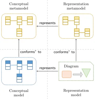
Diagram Conceptual metamodel Diagram Representation metamodel Conceptual model Representation model represents represents conforms? to conforms?to Diagram 1
Figure 1: Different models in free modeling space
levels of abstraction (model and metamodel) simultaneously and second, the development of a graphical syntax alongside the associated conceptual model. These ideas are better expressed through Figure 1. Amongst the four quadrants presented in the figure, the upper two represent a higher level of abstraction i.e. the meta-level. Whereas the bottom two quadrants represent the concrete level of modeling i.e. the instance models.
In traditional model driven engineering, a model is mostly developed or generated according to the concepts defined in its metamodel. Thus we need to develop the metamodel first and then afterwards, multiple models conforming to it can be developed/generated. For example, MDA architecture by OMG defines a four-layer hierarchy, where MOF is the top-most layer [13]. MOF allows the development of meta-models, which further allow the development of model and finally their instances. An ”instance-of” relationship between these layers restricts the instantiation of a modeling element without a prior definition of appropriate meta-modeling el-ement [8]. In a few modeling techniques, it is possible to create a model and then infer the metamodel from an ex-isting model [4, 9]. This metamodel then serves for further development of models. Free modeling allows to interact with models and meta-models at the same time. User mod-els and their metamodmod-els are shown as conceptual model and conceptual metamodel in the left quadrants of the Figure 1 The proposed process of modeling is highly interactive where new modeling elements, that do not conform to any of the elements of their metamodel, can be added to the instance model. If these elements are important enough or are fre-quently used in the model, the modeler can choose to infer the corresponding element to be added to the meta-model. The “conforms? to” mapping between models and
their metamodels, as shown in Figure 1, specifies that a model tends to conform to its metamodel, but in certain situations some elements in the model might not conform to any of the meta-elements. Similarly, while developing a model, a modeler can add meta-elements to the metamodel
first and then create new elements in a conforming model that conform to the newly added meta-elements. During model development, a modeler has the liberty to interact with the concrete and abstract levels at the same time.
The quadrants at the right side of Figure 1 pertain to the graphical representations of the models. Free modeling enables a modeler to add modeling elements into the con-ceptual models (and metamodels) either directly or through their graphical representations. This means that graphical representations can be added to a diagrammatic view of the model, from where elements can be added to the concep-tual models, subsequently. Graphical representations of the models are also presented in two abstraction levels. A con-crete diagram (representation model ) represents a concep-tual model and the abstract level representation metamodel defines the graphical representations of the meta-elements.
All the four quadrants seem to be tightly integrated with each other. However, the strength of free modeling method-ology lies in the fact that all four modeling spaces are very loosely bound. This means that a modeler can add modeling elements to any of the four models without affecting other models. The effect of a change in one model can be prop-agated to other models, if that is intended by the modeler. Having the possibility to interact with all four models at the same time alongside this decoupling allows the freedom to have multiple variations of interactions with the modeling space. This turns modeling into a highly interactive activ-ity that can be carried out alongside the client stakeholders, who are more comfortable in comprehending the diagram-matic representations of the models.
3.2
Free Modeling Environment
To validate the free modeling methodology and to put it into practice, we developed a tool that relies on Open-flexo [14]. OpenOpen-flexo is our open source initiative that started as a business process modeling workbench, but by integrat-ing our recent research endeavors it has evolved into a generic collaborative platform for multifaceted modeling. It uses the concept of model federation [7] to deal with multi-paradigm modeling and provides support for both graphical and tex-tual models.
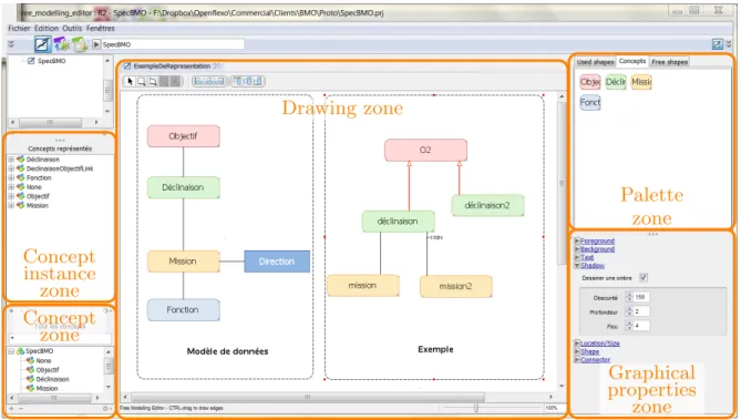
Free Modeling Editor (FME ) is a prototype for testing new modes of interaction with the models. It facilitates the development of a conceptual metamodel for a domain spe-cific modeling language alongside its graphical syntax. Its interface is partitioned into five main zones, as shown in Figure 2. The zones to the left deal with conceptual mod-eling for the domain specific languages, whereas the cen-tral and right zones are dedicated to a drawing tool that deals with the graphical representations of the conceptual models. A modeler can use the central drawing zone to de-velop graphical representations by dragging and dropping graphical shapes from one of the palettes provided in the palette zone. The graphical properties zone provides the pos-sibility to fine-tune the shapes drawn in the drawing zone. The concept zone and the concept instance zone serve as browsers for conceptual metamodel and conceptual model respectively. Free modeling editor is coherent with the free modeling methodology illustrated in Figure 1, with following mappings:
• Concept zone ←→ Conceptual metamodel • Concept instance zone ←→ Conceptual model
Drawing zone
Concept
instance
zone
Concept
zone
Palette
zone
Graphical
properties
zone
1
Figure 2: Free Modeling Editor
• Palette zone ←→ Representation metamodel • Drawing zone ←→ Representation model
The graphical shapes, not yet associated with a concept, appear under the term “None” in the conceptual model, to decouple it from its representation. It is possible to create a concept using a contextual menu in the conceptual zones, so that it is not associated with any graphical shape. A graphical shape in the drawing area can be associated to a concept through a contextual menu. If no corresponding concept exists, the user can create a new one.
Three kinds of palettes are available to the user for creat-ing graphical shapes:
• Used shapes: allows the reuse of shapes already defined in the current drawing. Using a shape from this palette creates a shape in the representation model.
• Free shapes: provides a set of simple shapes to create new representation. When a shape from this palette is dropped in the drawing zone, it creates a shape in the representation model and places that shape in the used shapes palette.
• Concepts: offers the shapes already associated with concepts. Dragging and dropping from this palette triggers both the creation of a shape in the representa-tion model and an instance of the associated concept in the conceptual model.
If a user wants to use some shape other than the ones provided in the Free shapes palette, it is possible to use an image provided by the user. The properties of all the shapes can be adjusted from the graphical properties zone. Graph-ical shapes are loosely coupled with the concept instances. When a concept and its graphical representation is created
through concepts palette, the designer still retains the possi-bility to change the association between them. In this case, the graphical shape associated with a particular concept in-stance is changed, however the concept (in the conceptual metamodel) retains the same graphical representation. It is also possible to restore this shape with the one associated with the concept, or, alternatively, replace the shape of the concept and impose on all other instances.
Lastly, it is possible to import a diagram developed as a part of an existing document (Microsoft Office suite files in this case) and use it as a graphical representation. In this case, no conceptual (meta)model is associated with the graphical representation. However, it gives a good starting point to develop models based on existing diagrams. This functionality serves for requirements elicitation and model-ing at the same time. Given the flexibility of the tool, it is easy to experiment with different modeling situations.
4.
EXPERIENCE REPORT
Our experience report concerns the application of free modeling methodology in the context of a problem faced at a local government institution, as described in Section 2.1. The elected representative of this institution used a set of vocabulary, diagrams and tools that was suitable for the strategic vision. Their activity maps were created in terms of objectives and targets, as shown in Figure 3. On the other hand, the government officials working at the opera-tional level, in charge of operaopera-tionalizing the strategy, used a completely different set of vocabulary and diagrams. They mapped their activities using assignments and tasks. Link-ing the operational level assignments and tasks to the strate-gic level objectives and targets was not an easy job for them, because of the variation in the types of vocabulary and doc-umentation. They were using Microsoft Office suite for
cre-Objective Target Assignment Task Directorate Operational level Strategic level Organization chart 1
Figure 3: Concepts in the problem domain
ating different types of documents like reports, presentations and databases (in Excel).
The project in this case study revolved around a solution based on graphical domain specific modeling. This project took around three months to complete in ten development iterations. Three members of our team were involved in this project, where two of them were actively involved in the co-development alongside client stakeholders in each iteration. A third one was responsible for the packaging and delivery of the tool after each iteration. Four members from this govern-ment institution (from both strategic and operational level) engaged as active participants for this project. None of these client stakeholders had any prior knowledge of model driven engineering. Few of the stakeholders had already used basic modeling tools (one stakeholder had used models for acoustic treatment and another developed process models) and one of them had worked on relational database engines. It needs to be noted that even the model presented in Figure 3 was not provided by the client institution, it was rather elicited during the implementation of the project. In such an envi-ronment, it is difficult to impose an existing modeling lan-guage, especially when we had to consider other constraints like: a shared (non-formal) vocabulary across the depart-ments of the institution and the demand to reuse existing graphical notations (diagrams). We had heterogeneous data at our disposal, both in terms of format and source:
• a spreadsheet containing information related to the ac-tivity maps
• a representation of the same information in the form of a mind map
• a document presenting the strategic objectives of the organization (unstructured information)
• some free form diagrams describing the operating en-vironment
• example documents using this information: scoping re-ports, activity rere-ports, documents for disseminating information and promoting the organization, etc. The project management team at the client institution ex-pressed their concerns for a maximum reuse of existing data (both their structure and format), in order to avoid con-siderable modifications to their existing work-flow. Several objectives were set for the project:
• facilitating information maintenance and its ownership by producers
• assisting in the alignment of strategic objectives (of elected representatives) with the activities (of the bu-reaucracy)
• producing graphical representations for different audi-ences
• opening new possibilities by linking current informa-tion with other data sources
We developed a set of tools using the infrastructure devel-opment capability of Openflexo [14]. This gave us the pos-sibility to use dynamic links between the conceptual models and the representation models (definitions of diagrams) for interpreting these models. So we were able to develop and test our models, working alongside the stakeholders from our client institution. To explain how we actually interacted with our client stakeholders, we do not use the terms model or metamodel in the rest of this section, we rather use the terms examples and concepts.
During the implementation of this project, we encountered different situations where specific modeling techniques were needed. We present three of such example scenarios from the analysis phase where we developed some concepts from their activity maps (provided document). Some of the concepts were easy to develop from the existing diagrams that our clients used in the provided documents. This first scenario, illustrated in Figure 4(a), describes this situation:
1. isolating a representation in the examples with a con-sensus: From the diagrams used by the operational level stakeholders in the institution, we isolated a spe-cific representation for an activity “Collect recyclable waste”. [step 1 of the figure]
2. identifying the concept: After discussions with the client stakeholders, we realized that they define such assign-ments to meet the targets set by the strategic level stakeholders. [passing from steps 2 to step 3 of the figure]
3. producing example diagrams to validate the choices: Once we had both the concept and its representation at our disposal, we could use it to develop instant demon-stration examples that were validated by the stake-holders.
Certain concepts were present in the problem domain, but did not have their graphical representations because the client stakeholders never used those concepts in their dia-grams. Such concepts were usually identified from other tex-tual documents or through interviews with the stakeholders. Our second example, in Figure 4(b), presents this scenario. 1. identifying a new concept during the discussions on a document: When we studied and then discussed the organization chart provided by our client in the form of a textual document, we identified that assignments are allocated to different directorates in their institution. [concept defined in step 1 of the figure]
2. defining a representation for this new concept: Once the concept of directorate was identified, we defined a graphical representation for this concept. This repre-sentation was defined with the help of the stakeholders, so that their choices can be taken into account directly during the implementation. [representation defined in step 2 of the figure]
Assignment name Conceptual metamodel name Representation metamodel CollectRW name = ... Conceptual model Collect recyclable waste Representation model 1 2 2 3 1 (a) A concept appears through abstraction
Directorate name Conceptual metamodel name Representation metamodel HR name = ... Conceptual model Human resources Representation model 3 2 3 1 1 (b) An instance appears through concretization Figure 4: Example scenarios in free modeling
3. creating an example diagram for validation: Having both the concept and representation at hand, we de-veloped instant examples that could be validated by our clients. [both concept instance and representation instance, as shown in step 3 of the figure]
In our first example scenario, a concept was developed ac-cording to the selected representation, thus at the end both of them were synchronized. Figure 5 (section a) shows a valid synchronization state after the execution of this sce-nario, with a tick mark. During the implementation of the second scenario, we came across a situation where the client grouped certain directorates under a common concept which was very close to directorate itself. In one of the examples, the client changed the color of the representation for direc-torate, thus creating a new representation without any as-sociated concept. Thus all the representations of this model could not be associated to their respective concepts, hence the invalid synchronization shown at the start of Figure 5 (section b). To refine our concept metamodel accordingly, we carried out the activities presented as scenario 3:
1. differentiating between the two representations, based on their meaning: We discussed with our client stake-holders, the reasons why a different color (representa-tion) was chosen for an instance of directorate. These discussions helped us identify a new concept, division, which was differentiated from the original concept. 2. associating a new concept to an already existing
rep-resentation: A representation for directorate concept was already defined in previous scenario. After the dis-cussions, when the concept of directorate was clarified by the stakeholders, we associated it with its already existing representation.
3. building a new concept from the other representation: During the implementation of previous scenario, an ad-ditional representation was developed with the change of color. That representation was intended for the con-cept of division, so we linked that representation with the concept.
Implementation of the third scenario brought us back to the state, where both conceptual metamodel and the rep-resentation metamodel were synchronized, as shown at the end of Figure 5 (section b).
In addition to the development of conceptual model and graphical representations, we also had to project the identi-fied concepts on databases (spreadsheets) used by the client institution. Using model federation, our tool allowed both the manipulation of data in spreadsheets through the graph-ical representations and the generation of diagrams from the spreadsheets. This interactive modeling methodology used in the implementation of this project was supported by our tool, throughout this case study. Overall, this experience helped us concretize our methodology and refine our devel-opment environment as well.
5.
PROJECT OUTCOMES
As a final deliverable of the project in this case study, we had to hand over a solution that can be used as an interface between the strategic level and operation level information in our client institution, as described in Section 2.1. We de-veloped a graphical domain specific language to model the information at both these levels. Existing tools like Excel and PowerPoint were linked with our graphical DSML ed-itor. This way, the language concepts could be developed from the diagrams developed at the client institution in the tools that they commonly use in their work-flow. Once the graphical DSML was developed, the tool could access data about the activities from two different Excel spreadsheets i.e. one for strategic level information and the second for the operation level. The organization chart of the institu-tion and other management data, developed as Excel spread-sheets, were also linked with the tool.
Existing tools used by our client institution like Word, Excel and PowerPoint are used to create files like .xlsx and .pptx. We take all such files as models and use model federation to link them to our solution. Model federation is an approach that enables the integration of heteroge-neous models [7]. The concept of model federation is analo-gous to componentization of models for developing a system.
Tool co-construction with the client
Tool usage by the client
Target name Assignment name from to name name ATarget name AnAssign name from to an example target an example assignment 1 sustainable use of resources collect recyclable waste initiate intern awareness campaign 1 Directorate name name ADirectorate name = ... a directorate 1 Administration Human resources Technical service 1 Division name Directorate name from to name name Adm name = ... TS name = ... HR name = ... from to to Administration Human resources Technical service Administration Human resources Technical service 1a) Synchronization state after scenario 1
b) Synchronization state after scenario 2
unknown graphical elements
1
Each model (including the model of the system under devel-opment) is taken as a component with defined interfaces. These interfaces are developed as model slots, which open a view to the structure and behavior of the connected model. We can imagine such a model slot as a mean to interpret the model’s content. Once a model is connected to the system, its data can be accessed and multiple operations for reading or writing can be performed on that model.
Once our solution software was connected to the sources of information (models), we could extract data from them. Then the graphical DSML developed in this case study was used to link the data from strategic level to operation level. Our tool allowed to manipulate the data, in their source models, from within it. Finally, we could generate multi-ple kinds of activity reports and templates as new models in .docx format. Thanks to model federation, our solution worked as a central hub for all different kinds of models (from different existing tools) used in their work-flow. So all these models could be manipulated from a single tool.
6.
LESSONS LEARNT
Our participation in this case study was a good learning experience of working with graphical domain specific mod-eling languages. We share some of the lessons learnt in this endeavor. These lessons should not be taken as absolutes, however they highlight some of the important issues faced by the people in model driven engineering community while opting for a graphical domain specific language solution. In-stead of a separate section, we discuss the related works while explaining the lessons learnt, where applicable. Lesson 1: Graphical domain specific modeling lan-guages offer valid and instant solutions.
Despite some unfavorable opinions about model driven en-gineering in the agile software development community [1], we had a very positive experience of using it in a real-life case study. We can not contest the case for all the technolo-gies used in model driven engineering, however the use of graphical domain specific modeling language allowed us to develop solutions for our client institution in an interactive manner. The graphical aspect of models, helped in reducing the communication gap between our team members and the client stakeholders. We were able to interact in a way that our clients felt actively involved in the development process. Free modeling editor allowed us to import the diagrams that were already developed by the client stakeholders. Once a diagram was imported into the tool, it was considered as a model with a graphical representation. As we used to have discussions over each imported diagram in our tool, we could identify the concepts from those diagrams. The iden-tification of a concept meant that we are adding a modeling element to the conceptual metamodel. Thus discussions on diagrams were resulting in the creation of the conceptual metamodel of a new graphical domain specific modeling lan-guage. As free modeling editor does not need to restart or recompile the complete working space after each modifica-tion to the metamodel, we could instantly develop examples based on the new metamodel. Even though our client stake-holders did not have any prior experience of working with model driven engineering, their feedback was very positive for this style of development.
Lesson 2: Agile methods for graphical domain specific
modeling languages is a success story.
Certain approaches for the development of graphical do-main specific languages rely on requirement models [5, 17]. These requirement models are then used to verify the DSML between domain experts and language development experts. The development process followed by such approaches is somewhat traditional, where the solution is built (normally iteratively) and then it is verified against the requirements once it is ready.
We followed an agile development process for the develop-ment of graphical DSML, as explained in Section 2.2. During the development process, we worked in joint sessions with our client stakeholders in small iterations. Each iteration was focused on both the interviews with client stakeholders for requirement elicitations and the solution development. At the end of each iteration, we were able to deliver a part of working solution that kept evolving with each session. Active development sessions alongside client stakeholders helped us develop a solution such that their wishes were taken care of instantly, both for the development of concep-tual model and the aesthetic aspects of the graphical user interface. The use of agile methods for the development of graphical domain specific modeling language in this case study proved to be a success story, according to the feedback of our client institution.
Lesson 3: The tools for the development of graphical DSMLs need to be flexible.
In the first two lessons, we learnt that graphical DSMLs of-fer valid and instant solutions and that agile methods should be employed for such practices. However, these arguments stay valid only if the supporting tool is flexible enough to
• allow inconsistencies: The tools should allow different levels of consistency support. Starting from the one, where it can act as a simple drawing tool with no se-mantics. The tool should gradually build or allow the modeler to build consistent models.
• allow instances without associated concepts: Even though it seems counter-intuitive to have instances without the concepts, this provision is important if concepts need to be developed from demonstrations.
• add constraints stepwise: As said earlier, the consis-tency support should be offered in gradual steps. Sim-ilarly, the tool should allow to add constraints for re-fining the graphical DSML gradually. Starting with a complete set of constraints at once, takes away the flexibility from the designer to interact with the stake-holders on partially developed concepts.
• allow instances from the same concept to have differ-ent represdiffer-entations: It might seem that having mul-tiple representations for a concept instance will intro-duce inconsistency to the diagrams. Following a free modeling methodology, we support flexibility for the modeler, so that he can experiment with multiple rep-resentations. This helps a developer for requirements elicitation at runtime. An end user might not need multiple representations for the final solution, but a developer can for sure exploit this capability, as we did in our example scenarios.
Lesson 4: A balance needs to be kept between consis-tency and flexibility.
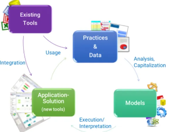
Practices & Data Models Application-Solution (new tools) Analysis, Capitalization Execution/ Interpretation Usage Existing Tools Integration
Figure 6: Graphical DSML development process
Excessively consistent approaches for graphical DSML de-velopment do not allow the possibility to execute models that have certain instances that do not conform to their metamodels. It is true for both conceptual model instances and their runtime representations. Similarly, they do not al-low instantiating representations without associated concept instances or at times concept instances that are not repre-sented in the diagrams. A balance needs to be found between consistency and flexibility. We have learnt through this ex-perience that this balance evolves during the development process. During the elaboration (specially in incremental approaches), the meta-model cannot always serve as a se-mantic reference. The sese-mantics of a meta-model is under development at this phase. For interactive development of DSMLs, we need to have the possibility to execute/interpret partial and inconsistent meta-models. As the development process advances, consistency is added to the meta-model and between other associated models e.g. representation models. We can inspire ourselves from textual model edi-tors to find a good balance. We find textual ediedi-tors that do not impose any consistency check, ones that offer error annotations for guiding the modeler and others that do not allow any code that is not consistent with the well-defined grammar. We can develop graphical editors that offer the same functionality according to the development phase. Lesson 5: Development processes need to consider the existing tools, practices, information and models.
During the implementation of this project, we came to realize that our client institution wants us to reuse the dia-grams used in their official routine. They also wanted to keep using their existing tools and resisted any considerable mod-ification to their existing work-flow. Thanks to the model federation capability of Openflexo, we were able to integrate their existing models1to our solution. Model federation also
allowed us to integrate other models (data models, applica-tion models, rule models and the models of DSML) for the development of a complete software solution.
In these circumstances, we followed a development process that could take into account existing tools both for integra-tion into the final soluintegra-tion and to understand the practices
1We consider all the artifacts involved in a process to be
models. In this specific case, we considered Word docu-ments, PowerPoint slides and Excel sheets to be models.
being followed at our client institution. This process, as illustrated in Figure 6, took existing tools to be the start-ing point for requirements elicitation. Once the practices of the client institution were identified and the data was acquired, we could analyze it to develop different models. These models were then used to develop software solutions for the clients. As explained earlier, we used an agile ap-proach where a deliverable software solution was developed at each iteration. This software solution was evolved over multiple iterations through the cycle presented in this pro-cess. The software solution integrated the existing tools used at the client institution.
Lesson 6: Interactive methods can exploit both the top-down and the bottom-up approaches.
We followed an interactive approach for the development of graphical domain specific modeling languages. Integra-tion of existing tools with the free modeling editor, allowed us to import diagrams from the existing documents used by our client institution. For example, we imported a diagram from a PowerPoint presentation used by the strategic level personnel of the institution. This diagram described actions like “Sustainable use of resources” which were refined into other actions like “Implement a waste reduction policy”. The shapes of the top level actions were represented by a differ-ent color scheme than the lower level ones. In discussions with the client stakeholders, we identified that the top level actions were strategic objectives and the low level actions were strategic goals. Once the diagram was in the drawing zone of free modeling editor, we could use the contextual menu to define the associated concepts with these shapes. This way we were interacting with the example models and the conceptual models (language metamodel) at the same time. Usual approaches for domain specific modeling follow a top-down approach [6,15]. We, on the other hand, focused on the bottom-up approach and found it to be useful in cer-tain situations. However we believe that a mix of both these approaches should be used for a graphical DSML develop-ment project, as we did for this case study (demonstrated through the example scenarios).
Lesson 7: Development of DSML language concepts from domain examples is effective.
Aligned to our methodology, Bak et al. suggest the use, of examples for eliciting, modeling, verifying and validating complex business knowledge for software development [2]. Domain examples are also used by some other approaches to develop the conceptual elements of the graphical DSML. A. Zolotas et al. use a type inference approach for calcu-lating the types from example models [18, 19]. They use algorithms based on classification and regression trees for this inference using shapes of the nodes and their context. Another approach uses grammar inference algorithms to re-cover metamodels for textual DSMLs [9]. H. Cho et al. use a metamodel inference engine to infer the metamodel based on their graph representations [4]. These approaches focus on automatic inference of concepts from the example models. Our focus, on the other hand, is not to infer metamodel using some algorithm, but to develop the conceptual metamodel alongside the client stakeholder using the example models. We focus on a flexible style of modeling, where models are not bound with the conformity to their metamodels, they are rather loosely coupled. Conformity of conceptual models to
their metamodels is a target to be achieved in the process of modeling, which marks the validation of developed models. We also focused on interactive development of a graphical DSML that could take diagrams from different sources al-ready used in the work-flows of different enterprises. An-other approach allows informal tools for the development of examples like Dia or yED, but does not offer the possibility of importing diagrams for office suites [12]. This approach also uses metamodel inference capabilities, but does not al-low the manipulation of individual models without affecting others, as illustrated in Figure 1.
During the course of this case study, we experienced that the development of a graphical DSML through the use of do-main examples improves model comprehension both for de-velopment teams and the client stakeholders. Construction of new examples from the developed concepts allow further discussions and eases requirements elicitation. These exam-ples can be used to refine the DSML, hence improving the quality of the models.
Lesson 8: It is better if the tool used for development is based on the same principles as the solution.
Our tool is itself developed on the same principles that we used to develop graphical DSMLs. This allowed a consistent approach for the development of solutions in the same fash-ion as the tool. It gave us the flexibility to modify our own tool whenever needed during the course of this case study. As our tool itself is not a fully functional commercial solu-tion and is still undergoing evolusolu-tion, this case study helped us test our tool in a real-life situation. Certain functional-ities demanded by the project and identified by the client stakeholders guided us to evolve it. This tool is developed using model federation and its graphical user interface uses the same approach used for the development of graphical DSMLs, as shown in Figure 1. This gave us the flexibility to evolve our tool according to the situation. The language experts, modeling the graphical DSML, were also the ex-perts of the tool, hence this evolution was at times instantly carried out during the joint sessions. We learnt that this approach is highly recommendable, especially for the tools that are still undergoing development.
Lesson 9: Further conceptual studies are needed for graphical domain specific modeling languages.
This case study allowed us to put our methodology into practice in a real life situation. On the one hand, we learnt some lessons about the development methodologies for graph-ical DSMLs. On the other hand, we also came across the lim-itations of the common understanding of graphical DSML development. Thus our last lesson learnt was that further studies are needed to concretize the conceptual basis of this domain. Some of the questions raised in this context were:
• What includes the definition of a graphical DSML; a metamodel, a representation metamodel, both or even more than that?
• What defines the syntax of a graphical DSML; concep-tual metamodel or representation metamodel? If both of them are taken as syntax (high level and low level) then, should the end users be allowed to modify both of them?
• To what extent, do we need a graphical representa-tion to conform to its metamodel? Example-based
ap-proaches cannot work if a strict modeling approach is followed. And on the other hand, excessive flexibility requires the end user to define details that could be included in the design as a feature of the approach. • How can we allow the end user to define semantics for
their languages? What should be the level of abstrac-tion that an end user can interact with?
7.
CONCLUSION
Many techniques used for the development of graphical domain specific modeling languages follow traditional soft-ware development life cycles. They perform the require-ments engineering activities, where requirement specifica-tions are prepared by domain experts. Language experts satisfy those requirements by the development of graphical domain specific language. We used an agile process for the development of graphical domain specific language in a case study involving a local government institution. In this case study, we merged the roles of domain expert and language expert in a single role, developer. Our developers worked alongside the client stakeholders for the development of this graphical DSML, using an interactive modeling approach. This approach was based on a methodology, free modeling methodology, that focuses on two things; first, simultane-ous development of models and metamodels for graphical DSMLs and second, the development of conceptual models alongside their graphical representations. This methodology was supported by our tool, free modeling editor, for the im-plementation of this project. In this article, we presented our experience report and shared the lessons learnt during the course of this case study. The modeling approach pre-sented in this article is flexible enough to deal with differ-ent situations, which are not common in traditional model driven engineering. Thus this article should be considered as a communication that opens multiple questions through our experience rather than answering them.
8.
ACKNOWLEDGMENTS
We are thankful to French national agency, Agence Na-tionale de la Recherche (ANR), for funding this research under FORMOSE project ANR-14-CE28-0009.
9.
REFERENCES
[1] S. W. Ambler. Agile model driven development is good enough. Software, IEEE, 20(5):71–73, 2003. [2] K. Bak, D. Zayan, K. Czarnecki, M. Antkiewicz,,
Z. Diskin, A. Wasowski, and D. Rayside.,
Example-driven modeling: model= abstractions+ examples. In Proceedings of the 2013 International Conference on Software Engineering, pages 1273–1276. IEEE Press, 2013.
[3] K. Beck, M. Beedle, A. van Bennekum, A. Cockburn, W. Cunningham, M. Fowler, J. Grenning,
J. Highsmith, A. Hunt, R. Jeffries, J. Kern, B. Marick, R. C. Martin, S. Mellor, K. Schwaber, J. Sutherland, and D. Thomas. Manifesto for agile software
development. http://agilemanifesto.org/, 2016. Online; accessed: 2016-07-30.
[4] H. Cho, J. Gray, and E. Syriani. Creating visual domain-specific modeling languages from end-user demonstration. In Proceedings of the 4th International
Workshop on Modeling in Software Engineering, pages 22–28. IEEE Press, 2012.
[5] H. Cho, J. Gray, and E. Syriani. Syntax Map: A Modeling Language for Capturing Requirements of Graphical DSML. In 19th Asia-Pacific Software Engineering Conference (APSEC), 2012, volume 1, pages 705–708. IEEE, 2012.
[6] A. Fouch´e, F. Noyrit, S. G´erard, and M. Elaasar. Systematic generation of standard compliant tool support of diagrammatic modeling languages. In ACM/IEEE 18th International Conference on Model Driven Engineering Languages and Systems
(MODELS), 2015, pages 348–357. IEEE, 2015. [7] F. R. Golra, A. Beugnard, F. Dagnat, S. Guerin, and
C. Guychard. Addressing Modularity for
Heterogeneous Multi-model Systems Using Model Federation. In Companion Proceedings of the 15th International Conference on Modularity,
MODULARITY Companion 2016, pages 206–211, New York, NY, USA, 2016. ACM.
[8] C. Gonzalez-Perez and B. Henderson-Sellers. A powertype-based metamodelling framework. Software & Systems Modeling, 5(1):72–90, 2006.
[9] F. Javed, M. Mernik, J. Gray, and B. R. Bryant. MARS: A metamodel recovery system using grammar inference. Information and Software Technology, 50(9):948–968, 2008.
[10] S. Kelly and R. Pohjonen. Worst practices for domain-specific modeling. IEEE Software, 26(4):22–29, 2009.
[11] S. Kelly and J.-P. Tolvanen. Domain-specific modeling: enabling full code generation. John Wiley & Sons, 2008.
[12] J. J. L´opez-Fern´andez, J. S. Cuadrado, E. Guerra, and J. de Lara. Example-driven meta-model development. Software & Systems Modeling, 14(4):1323–1347, 2015. [13] Object Management Group. MDA Guide revision 2.0. www.omg.org/cgi-bin/doc?ormsc/14-06-01.pdf, OMG Document ormsc/2014-06-01, june 2014. Online; accessed: 2016-07-30.
[14] Openflexo. Openflexo project. http://openflexo.org/, 2016. Online; accessed: 2016-04-08.
[15] A. Pescador, A. Garmendia, E. Guerra,
J. Sanchez Cuadrado, and J. de Lara. Pattern-based development of domain-specific modelling languages. In ACM/IEEE 18th International Conference on Model Driven Engineering Languages and Systems (MODELS), 2015, pages 166–175. IEEE, 2015. [16] J. Rumbaugh, I. Jacobson, and G. Booch. Unified
Modeling Language Reference Manual, The (2nd Edition). Pearson Higher Education, 2004.
[17] F. Zalila, X. Cr´egut, and M. Pantel. Leveraging formal verification tools for DSML users: a process modeling case study. In Leveraging Applications of Formal Methods, Verification and Validation. Applications and Case Studies, pages 329–343. Springer, 2012. [18] A. Zolotas, N. Matragkas, S. Devlin, D. S. Kolovos,
and R. F. Paige. Type Inference Using Concrete Syntax Properties in Flexible Model-Driven Engineering. In Flexible Model Driven Engineering Proceedings (FlexMDE 2015), page 22.
[19] A. Zolotas, N. Matragkas, S. Devlin, D. S. Kolovos,
and R. F. Paige. Type inference in flexible
model-driven engineering. In Modelling Foundations and Applications, pages 75–91. Springer, 2015.