HAL Id: hal-02469490
https://hal-univ-rennes1.archives-ouvertes.fr/hal-02469490
Submitted on 12 Mar 2020
HAL is a multi-disciplinary open access
archive for the deposit and dissemination of
sci-entific research documents, whether they are
pub-lished or not. The documents may come from
teaching and research institutions in France or
abroad, or from public or private research centers.
L’archive ouverte pluridisciplinaire HAL, est
destinée au dépôt et à la diffusion de documents
scientifiques de niveau recherche, publiés ou non,
émanant des établissements d’enseignement et de
recherche français ou étrangers, des laboratoires
publics ou privés.
Matthieu Bertrand, Guido Valerio, Mauro Ettorre, Massimiliano Casaletti
To cite this version:
Matthieu Bertrand, Guido Valerio, Mauro Ettorre, Massimiliano Casaletti.
RWG Basis
Func-tions for Accurate Modeling of Substrate Integrated Waveguide Slot-Based Antennas.
IEEE
Transactions on Magnetics, Institute of Electrical and Electronics Engineers, 2020, 56 (1),
�10.1109/TMAG.2019.2948491�. �hal-02469490�
RWG Basis Functions for Accurate Modelling of Substrate Integrated
Waveguide Slot-based Antennas
Matthieu Bertrand
1, Guido Valerio
1, Mauro Ettorre
2, and Massimiliano Casaletti
1 1Laboratoire d’Electronique et Électromagnétisme, Sorbonne Université, F-75005 Paris, France2IETR, UMR CNRS 6164, Université de Rennes 1, France
In this paper, we propose the implementation of a triangular mesh along with Rao-Wilton-Glisson (RWG) basis functions to improve the performance and flexibility of a mixed Mode-Matching (MM) / Method of Moment (MoM) algorithm dedicated to Substrate Integrated Waveguide (SIW) antennas analysis and optimization. These basis functions represent equivalent magnetic currents on either coupling or radiating apertures. In the initial implementation, entire domain sine basis function were presented, providing fast and accurate simulations for electrically thin rectangular slots. In order to treat wider slots and other geometries, we introduce here RWG functions, present the theoretical framework of this approach and highlight its potential through concrete examples.
Index Terms
—
Method of moments, Mode matching methods, Slot antennasI. INTRODUCTION
N recent years, planar microwave and millimeter-wave passive circuits have become increasingly critical parts of communication and imaging systems. In particular, the requirement for low-cost highly directive antennas has drawn attention to the substrate integrated waveguide (SIW)[1] technology. This led to the design of multilayer radiating SIW structures [2] of large electrical dimensions with many small apertures and metallic pins. As a result, the optimization of such structures with commercial full-wave codes is often proving to be a very time consuming and tedious task. While the latest general purpose methods such as in [3] are probably very attractive in this context, we proposed in [4] a dedicated hybrid MM/MoM which takes full advantage of the redundant geometrical properties of this structures, such as the presence of only cylindrical diffracting elements. Furthermore, the use of sine-shaped basis functions for the aperture currents provided a very accurate result for electrically thin slot geometries. However, it but was unable to deal with non-rectangular slots, or wide and longer slots exhibiting more complex currents distributions.
In this paper, we propose to add linear basis functions defined on triangular domains [5] (RWG), to deal with such cases. In Section II a general description of the hybrid code is given, followed by a more specific focus on the implementation of the coupling for RWG functions. In Section III, two examples are presented to highlight the advantages and limitations of both basis function types, while comparing the results to that of commercial software. Finally, conclusions are drawn.
II. THEORETICAL FORMULATION A. General considerations
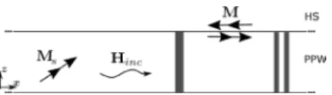
First, as explained in [3], the code relies on the combination of two numerical methods. The generic single-layer configuration is illustrated in Fig. 1. A MM is used to enforce the boundary conditions on metallic and/or dielectric cylinders
connecting horizontal metallic plates. In the meantime, apertures on these metallic plates are represented by equivalent magnetic currents and the fields are solved through the MoM. In this latter procedure, the equivalent currents M are expressed
on a set of Nb basis functions bn(r) such as:
1 ( ) Nb n n( ) n v = =
∑
M r b r (1)Then, a Galerkin scheme provides the current amplitudes vn
by solving the following linear system, where Y is the coupling
matrix and I is the so-called forcing term.
⋅ =
Y V I (2)
The coupling matrix elements are decomposed into a sum of three terms: the first term is related to the half-space (HS) propagation, the second to the guided parallel-plate waveguide (PPW) modes, and the third results from the diffraction by the posts inside the structure.
, 0 ' ' ' ( ( ( ( ( )· , )· ( ') ' )· , )· ( ') ' )· ( , )· ( ') ' HS k f P s k f S PW k f Po ts k S f S S S S Y dS dS dS dS dS dS j j j ωε ωε ωε = − − − ′ ′ ′
∫
∫
∫
∫
∫
∫
b r G r r b r b r G r r b r b r G r r b r (3)For each integral term, the proper Green’s function for magnetic currents is employed, i.e. GHS, GPPW, or GPosts,
respectively. Test and source currents domain are S’ and S, while ε0 and ε are the vacuum and substrate electrical
permittivities, and ω is the angular frequency.
I
Manuscript received August 1, 2019, revised on October 5th, 2019.
Corresponding author: M. Bertrand (e-mail: [email protected]).
Fig. 1. General configuration for the single layer version of the electromagnetic problem.
Finally, the forcing terms are the dot products of the incident magnetic field Hinc and test functions. Hinc is produced by a
coaxial or waveguide source represented by a equivalent magnetic current Ms in the absence of slots, it is computed
through the SIW Green’s function, which is the sum of GPPW
and GPosts([3]).
( )
( )
( )· , ) ) ( · ( S S k k inc k S Sour SIW ce S i dS d jωε
d = − ′ ′ ′ = ⋅ ∫
∫
∫
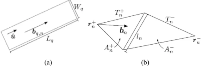
b r H r b r G r r M r r (4)The initial entire domain (ED) basis function set was based on a sine expansion, in particular, the current on the q-th slot was written as: q n, ( ) ˆ 1 sin 2q q q L n u W L π = + b r u . (5)
Note that the current (5) is directed along the slot length Lq
(u-axis) without variation along its width Wq, as shown on Fig. 2(a).
In this paper, we propose to hybridize the basis function set by adding piecewise linear variations on triangular domains, commonly known as RWG functions [5]. In particular, a basis function bn is defined on two adjacent triangles Tn+ and Tn-, of
respective areas An+ and An-, sharing a common edge of length ln. In each triangle, the vertex diametrically opposed to the
common edge is denoted rn±. Suitable normalization constants
ensure the continuity of the current component normal to the common edge:
(
)
(
)
if 2 ) if ( 2 n n n n n n n n n l T A l T A− + + + − − − ∈ = − − ∈ r r r b r r r r (6)A geometrical description of (6) is given in Fig. 2 (b).
B. Coupling matrix computation
We will focus here on the RWG basis functions, which constitute the novel part of this work. RWG basis functions are defined on pairs of triangles, so that each triangle can be part of up to three basis functions, inducing redundancy in the coupling terms. To avoid useless computation, the coupling is therefore computed between triangles. We will mainly deal here with the HS and PPW contributions, as the post diffraction is handled in the exact same way as in [4].
Two terms, , / , s HS PPW
Cα β and Cα βv HS PPW,, , ,i j/ , related to both scalar
, / / , ( , ) s HS PPW HS PP T T W g dSdS C α β α β =
∫ ∫
r r′ ′ (7) , / , , ,/ [ i ( )· j( ')] HS PPW( , ) v HS PPW T i j T C g dSdS α β α β =∫ ∫
Λα r Λβ r r r′ ′ (8)In these equations, α and β denote the triangles Tα and Tβ
while 𝑖𝑖, 𝑗𝑗 ∈ [1,3] indicates the considered free vertices. Finally, denormalized linear basis functions are defined as
( ) i i α α Λ r = −r r
and j( ) j β β Λ r = −r r , while gHS PPW/ (r r, )′ is
the scalar Green’s function. To obtain (7)-(8) these equations, the differential operator ∇ was transferred from the dyadic Green’s function onto the basis and test functions through integrations by parts. The constants resulting from the differentiation of RWG linear basis functions are added later in the recombination of the two potential contributions:
, / , / , , , , , /,, 4 v HS PPW s P HS PPW i j i j HS P W i j C j C j C A A A A l l α β α β α β α β α β α β ωε ωµ = − + (9)
In this equation, 𝑙𝑙𝛼𝛼𝑖𝑖 and 𝑙𝑙𝛽𝛽𝑗𝑗 stand for the length of the edges
directly opposite to the free vertices i
α r and j
β
r , 𝐴𝐴𝛼𝛼 and 𝐴𝐴𝛽𝛽 are
the areas of 𝑇𝑇𝛼𝛼 and 𝑇𝑇𝛽𝛽, while 𝜀𝜀 and 𝜇𝜇 refer to the considered
me-dium permittivity and permeability, respectively. Finally, the MoM matrix is obtained by adding the proper contributions for each basis function pair.
We will now focus on the different methods implemented to compute the integrals (7)-(8). Depending on the distance be-tween the coupled elements, spatial, spectral or asymptotic rep-resentations were adopted. First, let us consider the coupling re-sulting from half-space radiation. The singular integrals appear-ing in self or adjacent couplappear-ings are treated as in [6]. In particu-lar, the divergence theorem is applied twice in order to transform the two surface integrals on the triangles to a numerical integra-tion on their edges of an analytical integrand. These transfor-mations also cancel the singularity in 1/R. For non-singular cou-plings, a straightforward triangular Gauss-Legendre integration is applied with the Green’s function spatial representation given by | | , ) 2 | | ( jk HS g e
π
′ − − ′ = ′ − r r r r r r (10)(a factor 2 is added to take into account the presence of the infi-nite plane on which the source is lying.)
Secondly, we will give more insight into the coupling related to the field excited in the PPW regions. By applying the equiva-lence theorem iteratively, a magnetic current source between two metallic planes can be replaced by an infinite periodic array of sources having doubled amplitude separated by twice the waveguide thickness h. All of these sources radiate in free space so that the total scalar Green’s function is given by:
ˆ ( , ) ( , 2 ) PPW HS n g + g nh =− ∞ ∞ ′ =
∑
′+ r r r r z (11) One should pay attention to the 𝑛𝑛 = 0 term, which is singu-lar for all triangles sharing one or more vertex, and it is here treated again as in [6]. This formulation is particularly suited for(a) (b)
Fig. 2. (a) ED basis function defined on an entire slot, (b) RWG basis function defined on a pair of mesh triangles defined inside a slot.
close coupling, as the lowest order terms dominate the sum. For couplings at greater distances, the following spectral expansion involving a few cylindrical waveguide modes is more suitable:
(2) 0 2 2 2 2 , , , 2 2 2 2 , , 1 , ) ( |) 8 , ( | , , PPW m m z m z m m z m z m z m H k jh k k k k m k k h g j k k k k ρ ρ π ∞ =−∞ ′ − ′ − > = − − < = =
∑
r r r r (12)This last formulation is particularly efficient for thin wave-guides, in which the higher-order modes are rapidly attenuated. Again, for representations (11) and (12) a Gauss-Legendre inte-gration is adopted. Finally, an asymptotic approximation of the integrals was implemented for the couplings at large distances. The coupling is first expressed in the spectral domain, the vector between the coupled triangles centroids is ραβ =
ρ
αβ αβρˆ , 𝜂𝜂 isthe wave impedance, and the wavenumber is written as
ˆ (ˆ ˆ ) x y h αβ h αβ = + × h ρ z ρ : ˆ , , , (21)2 ( ) ( ) j PPW PPW i j C M e αβραβg d α β
π
+∞ +∞ − −∞ ∞ ⋅ − =∫ ∫
h h ρ h h (13) where M(h) is given by(
2)
, , ( ) ( ) 4 ( ) j i i j M l l k A A α β α β α β − ⋅ ⋅ = h 1 −hh h h Λ Λ (14)and the Green’s function Fourier transform by
2 0 1 ) ( PPW m m m jhk k g ρ ε η ∞ = = − ⋅
∑
h h h (15)where 𝜀𝜀𝑚𝑚 is 1 for 𝑚𝑚 = 0 and 2 otherwise.
Then, adapting the derivations from [7] to the RWG case and neglecting attenuated higher-order modes, the coupling reduces to the integral (16), evaluated by a Gauss-Hermite integration.
0 2 0 , , , 2 2 0 0 2/ 2 2 ( (1 ), 2 2 ) 1 jk i j k P s PW e C j jhk M k js k s j s e d s s j ρ αβ ρ αβ ρ α β ρ ρ ρ π η − +∞ − −∞ × − + − = −
∫
(16)III. NUMERICAL RESULTS AND VALIDATION
In order to evaluate its accuracy, the code was used to compute the field radiated by two previously realized large antennas, a radial line slot antenna (RLSA) [8], and a dual reflector leaky-wave antenna (LWA) [9], depicted in Fig. 2. The first antenna is composed of radially arranged radiating slots fed by a single coaxial feed in its center. It was designed in [8] to radiate a specific distribution of z-oriented electrical field in the near field. The second antenna radiates a pencil beam in the far field. Two coaxial sources on the left side of the structure in Fig. 2(b) generate an impinging wave on a Gregorian system feeding the arrays of slots. Both structures exhibit a large number of either metallic posts, slots, or both, making them interesting test structures for the developed numerical tool.
A commercial FEM code (HFSS) and a time domain solver based on Finite Integration Technique (CST) were also used for comparison. However, we were unable to obtain a proper
evaluation of the near field radiated by the RLSA with HFSS FEM method due to the required large airbox needed to evaluate the field, introducing resonances and a poor field evaluation. For all simulations, we used an Intel-Core i7-3770 CPU at 3.40 GHz with 32 GB of RAM.
A. Accuracy
Starting with the RLSA antenna, the normalized z-component evaluated at a distance of 150 mm of the antenna plane is illustrated in Fig. 3. All methods provide a good estimation of the pattern, especially for the three main lobes. The differences on the lateral lobes can be attributed to fabrication tolerances and edge diffraction effects. While the measured antenna is offinite size, our code assumes an infinite structure, while CST approximates an absorbing boundary to imitate free space propagation.
Secondly, the different evaluations of the radiated normalized far field of the LWA, as well as the measurement results, are presented in Fig. 4. Due to the strong asymmetry of
(a) (b) Fig 3. Photograph of the simulated antennas, (a) RLSA, (b) LWA, respectively from [8] and[9].
Fig 4. Normalized near-field z-component of the RLSA at a distance of 150 mm, along with measurement data extracted from [8].
the pattern, it is here calculated in the two cut planes defined in spherical coordinates by 𝜑𝜑 = 0 degrees and 𝜑𝜑 = 90 degrees.
In this particular case of relatively large slots, the ED basis functions do not produce the correct maximum directivity angle. On the contrary, one can see that the response with RWG functions is much closer to the measured data. It is also in agreement with the results provided by commercial software, in particular with the time domain solver CST.
When comparing the accuracy of the solutions, one should keep in mind that the proper evaluation of the post diffraction in both HFSS and CST depend on the accuracy of the 3D mesh, the former being hexahedral, the latter cubic. While the chosen mesh is important also with RWG basis functions to describe currents on slots - in this case, 18 of them are sufficient to provide these results -, the post contribution is exact, as the full cylindrical shape is included analytically in the MM boundaries.
B. Timing and memory comparisons
The computation time of all simulations, as well as the memory consumptions, is summarized in Table I. Considering first of all the time required to solve each antenna problem, it is clear that the MM/MoM is much faster than the commercial codes in both cases. Starting with the RLSA, the ED provides in less than 6 minutes the pattern given by CST after more than 9 hours of simulation. In this case, the RWG offer also a significant time gain but it requires more basis functions, indicating that resonant slots are indeed more easily represented on the sine basis. For the LWA, the RWG set provides the solution in less than 5 minutes, compared to 45 minutes in HFSS and 37 hours in CST. The ED computation is even faster but is unable to reach the physical solution.
As far as memory is concerned, the ED formulation is always more advantageous because of its simplicity. In the RLSA case, ED only requires 2.2 GB of RAM for the RLSA, while the RWG formulation needs 20.1 GB and CST 10.7 GB. For the LWA case, HFSS (which is able to solve the problem in a reasonable time) requires 21.3 GB of memory, versus 10 GB and 3.5 GB needed by the RWG and ED basis functions, respectively. Overall, the MM/MoM still requires a decent amount of memory for large antennas but using the proper basis functions one can expect to about half the memory burden of current commercial codes.
C. Discussion
Beyond a straightforward comparison of the memory usage and time consumption, several points will be discussed here that are essentials for the optimization of large SIW antennas.
First, while a simulation with a single set of geometrical parameters indicates how fast the method can be, it hides the fact that during an optimization procedure, only a few of them would be modified at each iteration. This is significant because
HFSS or CST would require a complete re-meshing.
Second, while the commercial software can only deal with one or two symmetry planes, this hybrid code takes into account further symmetries, by recycling all identical couplings. This significantly reduces the computation time for antennas with some type of periodicity, as in the cases presented here.
Third, in many beam-forming networks SIW solutions, pins are used in large number to create reflectors following the quasi-optics principles. This leads to geometries such as the one presented in this paper, where the coupling between slots induced from the diffraction of the pins is most of the time negligible compared to the half-space and parallel-plate waveguide contributions. Knowing this, a significant time can be saved in the computation.
IV. CONCLUSION
We presented the hybridization of the basis functions in a MM/MoM code for SIW antennas. With the addition of RWG functions providing a better description of the currents, the numerical tool is now able to deal with electrically large slots, but also any kind of non-rectangular geometries. A significant time and resource reduction can be obtained in comparison with commercial solutions. The authors intend to demonstrate in future works the code potential for large antenna optimizations.
V. ACKNOWLEDGMENT
The authors would like to thank the Direction Générale de l’Armement (DGA) for its financial support through the ANR ASTRID Fast-HEM-3D project. We would also like to thank the authors of [8] and [9] used as a basis for the numerical comparison done in this paper.
REFERENCES
[1] D. Deslandes and K. Wu, “Integrated microstrip and rectangular wave-guide in planar form,” IEEE Microw. Wireless Compon. Lett., vol.11, no. 2, pp. 68–70, Feb. 2001.
[2] J. Xu, Z. N. Chen, X. Qing and W. Hong, "140-GHz TE20-mode dielec-tric-loaded SIW slot antenna array in LTCC," IEEE Trans. Antennas Propag., vol. 61, no. 4, pp. 1784-1793, April 2013.
[3] R. Torchio, P. Alotto, P. Bettini, D. Voltolina and F. Moro, "A 3-D PEEC formulation based on the cell method for full-wave analyses with conduc-tive, dielectric, and magnetic media," in IEEE Trans. Magnetics, vol. 54, no. 3, pp. 1-4, March 2018, Art no. 7201204.
[4] M. Casaletti, G. Valerio, J. Seljan, M. Ettorre, and R. Sauleau, "A full-wave hybrid method for the analysis of multilayered SIW based anten-nas," IEEE Trans. Antennas Propag., vol. 61, no. 11, pp. 5575-5588, Nov. 2013.
[5] S. Rao, D. Wilton, and A. Glisson, "Electromagnetic scattering by surfaces of arbitrary shape," IEEE Trans. Antennas Propag., vol. 30, no. 3, pp. 409-418, May 1982.
[6] D. R. Wilton, F. Vipiana, and W. A. Johnson, “Evaluation of 4-D reaction integrals in the method of moments: coplanar element case », IEEE Trans. Antennas Propag., vol. 65, no 5, p. 2479 2493, mai 2017.
[7] M. Albani, A. Mazzinghi, and A. Freni, "Asymptotic approximation of mutual admittance involved in MoM analysis of RLSA antennas," IEEE Trans. Antennas Propag., vol. 57, no. 4, pp. 1057-1063, April 2009. [8] M. Ettorre et al., "On the near-field shaping and focusing capability of a
radial line slot array," IEEE Trans. Antennas Propag., vol. 62, no. 4, pp. 1991-1999, April 2014.
[9] M. Ettorre, A. Neto, G. Gerini and S. Maci, "Leaky-wave slot array antenna fed by a dual reflector system," IEEE Trans. Antennas Propag., vol. 56, no. 10, pp. 3143-3149, Oct. 2008..
Commercial tools This work
(RWG) This work (ED)
HFSS CST
RLSA RAM Time -- -- 9 h 21 min 10.7 GB 20.1 GB 28 min 5 min 20 s 2.2 GB
LWA Time 45 min 37 h 4 min 45s 3 min 25 s
![Fig 4. Normalized near-field z-component of the RLSA at a distance of 150 mm, along with measurement data extracted from [8]](https://thumb-eu.123doks.com/thumbv2/123doknet/11498332.293467/4.918.113.434.132.233/fig-normalized-field-component-rlsa-distance-measurement-extracted.webp)
