HAL Id: hal-02119945
https://hal.archives-ouvertes.fr/hal-02119945
Submitted on 9 Jun 2019
HAL is a multi-disciplinary open access
archive for the deposit and dissemination of
sci-entific research documents, whether they are
pub-lished or not. The documents may come from
teaching and research institutions in France or
abroad, or from public or private research centers.
L’archive ouverte pluridisciplinaire HAL, est
destinée au dépôt et à la diffusion de documents
scientifiques de niveau recherche, publiés ou non,
émanant des établissements d’enseignement et de
recherche français ou étrangers, des laboratoires
publics ou privés.
of a Bolted Assembly
V. Rafik, Bertrand Combes, Alain Daidié, C. Chirol
To cite this version:
V. Rafik, Bertrand Combes, Alain Daidié, C. Chirol. Experimental and Numerical Study of the
Self-loosening of a Bolted Assembly. Advances on Mechanics, Design Engineering and Manufacturing II,
pp.85-94, 2019, �10.1007/978-3-030-12346-8_9�. �hal-02119945�
Experimental and numerical study of the
self-loosening of a bolted assembly
Abstract
The self-loosening of a bolted assembly is a phenomenon that has been studied sever-al times in the past. Among the stresses present, it has been shown that transverse loading might cause the most severe loosening. Thus, different explanations have been proposed. In spite of their similarity, as they all consider sliding as the root cause, they can be distinguished from one another by the surface that is considered to slide. This paper aims to give another point of view of the overall problem in order to support Zadoks’ theory [7], which highlights the transverse sliding of components. For this, firstly, a double-shear assembly will be modeled. Its specificities are the pre-load application by screwing the nut, and the use of a self-locking nut. Secondly, some tests will be done in order to validate the model built. The experiments will also take account of the effect of the thickness of the assembly in the self-loosening. Thirdly, the analysis of the numerical results and of the experiments, especially the in-terface surfaces, will give us a clue enabling us to approach the sliding phenomenon, which is, according to Zadoks, the movement leading to self-loosening of the assem-bly.
Keywords: Numerical analysis; bolt; self-loosening; experiments.
1 Introduction
1.1 Industrial and scientific context
When a structure is loaded, its bolted joints are also subjected to displacement or loading. This excitation might be the root cause of phenomena that imply degradation of the assembly. Some of them are characterized by a loss of the normal load within the bolt. If this loss is too great, the assembly might no longer behave as an embed-ding and the structural integrity might be endangered. In order to increase the life of a bolted joint, it is often decided to increase the preload. Unfortunately, to avoid any plasticity within the bolt, the diameter of the screw then needs to be increased, leading to additional mass compared to the initial choice of component. It has been observed
that this loss of preload can be caused by the rotation of the nut on the screw [1]. A better understanding of self-loosening may reduce the weight of the structure without impacting its lifetime.
In order to carry out a phenomenological study of the self-loosening of a bolted as-sembly, the phenomena implying the loss of preload need to be understood. Numer-ous researchers have taken an interest in this subject ([1, 2, 3, 4, 5, 6, 7, 8, 9, 10, 11, 12, 13]). However, it is important to distinguish two general aspects of the loss of pre-load: untightening and unscrewing. On the one hand, untightening implies a loss of preload without any relative movement between the nut and the screw. Creep or rela-tive dilatation can be one of its causes. On the other hand, unscrewing is mostly linked to the geometry of the threads as the nut or the screw will rotate whereas the other component will not [6, 9, 10, 12]. Self-loosening, the phenomenon studied in this paper, is one of the unscrewing behaviors.
Several authors have worked on this phenomenon. The most outstanding works are presented below.
1.2 State of the art on self-loosening
Dinger [2] distinguished 4 different situations of loading which can lead to self-loosening of a bolted assembly:
Cross-load: the stress is orthogonal to the bolt’s axis,
Axial centered load: the stress is coincident with the bolt’s axis,
Axial decentered load: the stress is parallel to, but not coincident with, the bolt’s ax-is.
Rotational load: the bolt is subjected to a torque in a direction coincident with its axis.
He concluded that transverse loading is the most severe stress in terms of self-loosening. Since our aim is to study the most critical stress, in this paper, we shall on-ly consider cross-loading.
Junker [2] seems to be the first scientist to have studied self-loosening. He designed a specific test bench in order to study it. Thanks to this device, Junker highlighted the importance of nut or screw head sliding in the phenomenon. He also considered that the bending of the screw was the deformation that induced the sliding of these differ-ent surfaces. Koch [1] proposed a deeper explanation based on Junker’s observations and further tests. He considered that self-loosening could be divided into 4 steps, Fig-ure 1:
Step 1: the plate does not move relative to the frame
Step 2: the plate slips on the frame, the screw starts to bend as its nut and head are immobile relative to the plate but sliding occurs in the threads,
3
Step 3: the screw continues to bend but, beyond a certain displacement, either the nut or the head starts to slide on the plate; loosening seems to occur during this step,
Step 4: the screw is again in a configuration where the nut and the head do not move with respect to the plate.
Fig. 1. The 4 phases leading to self-loosening, from [3].
In addition to proposing an explanation for self-loosening, Koch also studied the early stage of the phenomenon. Like Sanclemente or Pai [2, 13], he highlighted the fact that self-loosening could occur even if sliding did not affect the whole surface of the con-tact. Pai named this movement local slip. When the screw bends, the pressure distri-butions between the nut, or the screw head, and the plate are modified. At some points, the pressure is sufficiently high for the tangential component to overcome the frictional force, implying slipping of the surfaces. At other points, it is weak and sur-faces will stay together. The possibility of unscrewing under the sole effect of local-ized slip is still disputed.
Zadoks [7] also studied self-loosening under transverse loading. Unlike Dinger or Koch, he thought that the sliding in the threads was not only circumferential but might have other components. The only sliding he considered was the sliding of the head on the plate. He took the bending of the screw, the deformation of the plate and the influ-ence of the transverse slip velocity into account. According to him, the transverse sliding modified the direction of the friction force, lowering the value of the friction torque.
1.3 Aims of the study
Most of the models built to study the self-loosening of bolts concentrate only on the screw, the nut being modeled as a threaded insert ([2, 3, 13]). The clamped parts are rarely considered ([1, 3, 6, 8, 9, 11, 13]). As the threads are not modeled most of the time, the preload is applied through a bolt load and by the relative rotation of the nut on the screw ([1, 2, 6, 9, 11]). This movement might deform the threads plastically and might impact the behavior of the bolt when it is cross-loaded.
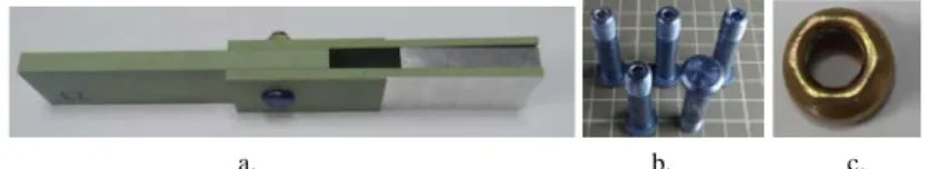
In order to build a model that takes account of these remarks, a double lap assembly will be used, as shown in Figure 2.a. A deformed locking nut and an aeronautical screw will be considered. The screw is kept still during tightening by a hexagonal hol-low on its threaded side. Figure 2 (b. and c.) presents these components. As the screw is not kept still by its head, it will not be subjected to any twist during tightening.
a. b. c.
Fig. 2. A double lap assembly (a.), an aeronautical screw (b.) and a self-locking nut (c.)
The aim of the paper is to propose an explanation based on Koch [8] and Zadoks’ theories. Observations made during experiments and analysis of the numerical results and of the contact surfaces will be made in order to determine their sliding direction and amplitude.
2
The numerical model
2.1 Presentation of the model
Abaqus software was used to model the self-loosening of the cross loaded double-lap assembly shown in Figure 2. It was composed of a 9.52 mm diameter, 31.31 mm long titanium aeronautical screw, having pitch and thread lengths of 1.05 mm and 10.65 mm, respectively; a self-locking steel nut and three aluminum plates: two having a thickness half that of the screw and one a thickness equal to that of the screw. Clear-ance between the screw rod and the plates was 40 µm.
To obtain reliable results, the threads needed to be more finely meshed than the other parts of the bolt, so two parts were created in the screw model (Figure 3). The average element size was 0.1mm in the body while the thread element size was 0.01 mm. A rigid connection was specified between surfaces to keep the parts together. The same method was used to mesh the nut.
5
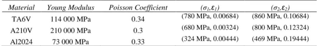
Three materials were described in the model by means of their Young modulus, Pois-son coefficient and kinematic plastic law, defined by two (stress – strain) pairs that set the last point of elastic deformation, (σ1,ε1), and the last point before failure, (σ2,ε2).
TA6V titanium was used for the screw (blue in Figure 4), the nut was made of A210V steel (yellow in Figure 4) and 2024 aluminum was used for the plates (green in Figure 4). The parameters used are summed up in Table 1.
Table 1. Definition of the materials.
Material Young Modulus Poisson Coefficient (σ1,ε1) (σ2,ε2)
TA6V 114 000 MPa 0.34 (780 MPa, 0.00684) (860 MPa, 0.10684) A210V 210 000 MPa 0.3 (680 MPa, 0.00324) (800 MPa, 0.12324) Al2024 73 000 MPa 0.33 (324 MPa, 0.00444) (469 MPa, 0.19444)
In order to be closer to a real assembly, several contacts were defined, the friction co-efficients of which were measured in torque – preload tests. The plates were coated with primer and the threads were lubricated:
Contact n°1: between the head of the screw and the upper plate, f = 0.27, Contact n°2: between the middle plate and the upper or lower plate, f = 0.35, Contact n°3: between the lower plate and the nut, f = 0.43,
Contact n°4: between the hole of the plate and the screw, f = 0.35,
Contact n°5: between the threads of the nut and those of the screw, f = 0.07.
2.2 Numeric simulation
The penalty method was chosen to model the normal and tangential behaviors. Four steps were considered to correctly simulate the self-loosening of the assembly: Step 1: deformation of the nut in order to self-lock it, Figure 4.a,
Step 2: tightening of the nut, Figure 4.b, Step 3: relaxation of the assembly, Figure 4.c,
Step 4: cross-loading of the assembly, Figure 4.d.
a. b. c. d.
Fig. 4. The four steps of simulation.
The first step is the deformation of the nut. Plastic strain due to three radial forces (Figure 4.a) makes the nut oval.
The second step of the model is the tightening of the bolt by screwing the nut at a torque of 22 Nm, corresponding to an average preload of 60% of the Ultimate Tensile Strength. As the nut is self-locked, a locking torque needs to be overcome before ac-costing the plate as shown in Figure 5. Three main parameters need to be validated: the locking torque, the preload and the tightening torque. These characteristics can be deduced from the evolution of the preload and the tightening torque during this step, as shown in Figure 5.
Fig 5. Evolution of the tightening torque (on the left) and the preload (on the right).
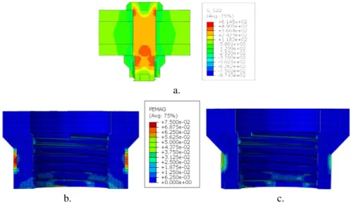
The values of the tightening torque and of the deformation load used to deform the nut during step 1 were chosen in order to be in agreement with Airbus standards for this kind of bolts. The preload was measured from the evolution of the axial compo-nent of the stress in the screw rod. As can be seen in Figure 6.a, the screw is in ten-sion whereas the plates are compressed. However, as can be seen in Figure 6.b and c, the tightening steps create some plastic strain, even in the threads.
a.
b. c.
Fig. 6. Axial stress distribution (a.), and magnitude of the plastic strain at the integration point before
tightening (b.) and after tightening (c.) Final torque
7
Cycling
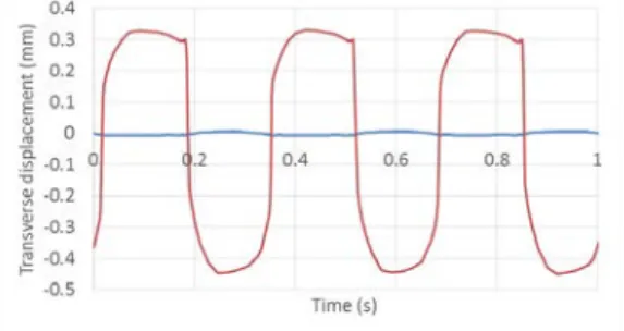
After a relaxation step, the last step to be simulated is the cross-load of the assembly. A sinusoidal load of 31 kN is applied to the middle plate. Once the transverse load overcomes the friction between the clamped parts, the medium plate slides on the up-per and lower ones. As soon as the medium plate contacts the screw, the latter starts to bend. The transverse sliding of the nut can be observed when the transverse load reaches a certain value. Figure 7 highlights the evolution of the transverse relative displacement between the nut, or the screw head, and its bearing surface.
Fig.7. Transverse sliding of the nut (in red) and the screw (in blue)
According to Zadoks, this movement would also imply the rotation of the nut and thus its loosening. It can be noted that the curve is not symmetric. In its initial configura-tion, the bolt might not be centered in the hole of the plate, so the transverse sliding might differ according to the direction. Moreover, because of different friction coeffi-cients, the amplitude of displacement is bigger for the nut than for the screw, and therefore the rotation of the nut should be greater than that of the screw. In order to check this theory, the rotation of the nut and the screw have been drawn Figure 8. The results are presented for the first five cycles. Assuming that the loosening speed re-mains the same over the whole step, the loosening angle after 500 cycles should be 73°.
Fig. 8. The loosening angle of the screw (in blue) and the nut (in red)
In order to obtain results representing the self-loosening of a real assembly as closely as possible, the value of the cross-load, implying the loosening of the bolt, needed to be determined. Thus, specific tests were carried out to determine the amplitude of
ro-tation of the different components for a specific load after a predefined number of cy-cles. They are presented below.
3
Experimental validation
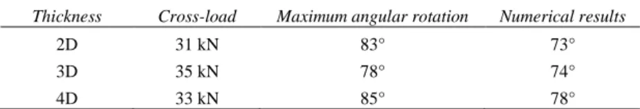
The tests needed to validate the numerical model could also be used to highlight some specifications linked to Zadoks’ explanation. According to him, the loosening of a bolted assembly is due only to the cross-load and to the sliding at the bearing surfaces of either the nut or the screw; the thickness of the clamped plates should not have any influence on the loosening process. In order to verify this theory, three different thicknesses were tested: 2D, 3D and 4D, D being the diameter of the bolt. A test sam-ple can be seen Figure 2.a. Its geometry is the same as the modeled one. The tighten-ing torque was the same as for the numerical model and the tests were load driven us-ing a 100 kN fatigue test bench (INSTRON 850l). A sinusoidal shape, with R = -1 and frequency = 3Hz, was chosen for the cross-load. Its amplitude started at 1 kN, and was increased by steps of 2 kN every 500 cycles. We considered that a rotation of 80° was equivalent to a complete loss of preload, as such a rotation was caused by the tightening torque. The rotation was measured every 500 cycles and the test was stopped if rotation exceeded 80°.
For each thickness, the bolt started to loosen for a cross-load of around 32 kN as can be seen in Table 2. Thus the thickness of the assembly does not seem to have any im-pact on its behavior. Moreover, for every test, only the nut rotated and its average amplitude of rotation was 80°, which is equivalent to a complete loss of preload. The rotation at the end of the tests can be seen in Table 2, where the cross-load at the start of the loosening is also given. It can be seen that the rotation of the nut obtained in the numerical model matches the experimental results: the model seems to reproduce the self-loosening of the real assembly.
Table 2. The maximum angular rotation and the cross-load for 3 different thicknesses
4
Self-loosening explanation
According to Zadoks’ theory, the sliding of either the nut or the screw on their bear-ing surfaces will imply the self-loosenbear-ing of the bolt. Moreover, as shown before, on-ly the nut loosens, so the contacts between this component and the plate will be ana-lyzed. The plates are painted with primer and sliding of the nut might remove the
Thickness Cross-load Maximum angular rotation Numerical results
2D 31 kN 83° 73° 3D 35 kN 78° 74° 4D 33 kN 85° 78°
9
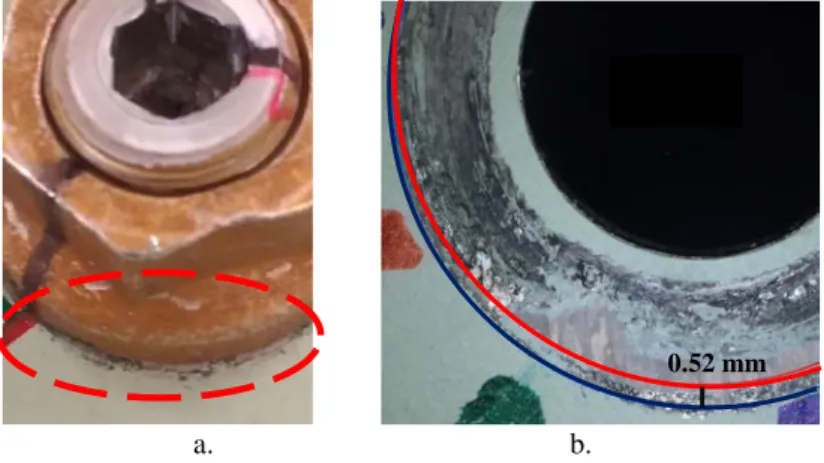
coating where the nut has slid. If we take a closer look at the nut (Figure 9.a), a dam-aged area can be seen.
a. b.
Fig. 9. Damage of the paint under the nut.
To determine the sliding displacement, the nut was removed after the test and the marking due sliding was analyzed. As the diameter of the nut was known, the approx-imate external positions of the nut during the slip could be determined (Figure 9.b). A relative displacement of 0.52 mm was measured between these two positions. Such sliding is the root cause of loosening according to Zadoks’ explanation. Thanks to the numerical model developed, this value of transverse sliding was also calculated. The maximum value found was 0.527 mm, which matches the experimental measurement.
5
Conclusion
Since the beginning of the 1970s, sliding has been considered as the root cause of self-loosening. Junker was the first to propose an explanation based on experiments performed on a specific test bench. He based his explanation on sliding movements, which were due to the bending of the screw when the assembly was cross-loaded. Za-doks showed that, beyond a certain transverse load, the nut or the screw slides on the bearing surface, leading to the loosening of the joint.
In order to prove that either the nut or the screw was sliding on the plate, a numerical model was developed. In comparison to existing studies, the specificity of the model lay in the complete modeling of the threads, the plastic deformation of the nut to self-lock it, and the tightening of the joint thanks to the rotation of the nut of the screw. The model was verified by experiments. In addition, the tests also highlighted that the thickness of the assembly had little influence on the behavior of the cross-loaded as-sembly. An analysis of the surface under the nut showed that the nut slipped on the plate. According to Zadoks’ theory, this sliding is sufficient to loosen the bolt.
References
[1] G. Dinger, Design of multi-bolted joints to prevent self-loosening failure, Journal of me-chanical engineering science, 2016, Vol. 230 (15), p.2564 - p.2578, DOI: 10.1177/0954406215612813
[2] J.A. Sanclemente, D.P. Hess, Parametric study of threaded fastener loosening due to cyclic transverse load, Engineering Failure Analysis, 2007, Vol.14, p.239 – p.249
[3] S. Izumi, T. Yokoyama, A. Iwasaki, S. Sakai, Three-dimensional finite element analysis of tightening and loosening mechanism of threaded fastener, Engineering Failure Analysis, 2005, Vol.12, p. 606 – p. 615.
[4] J. Dominik, M. Zmindak, Spontaneous Unfastening and fatigue of Bolted Joints, Manuf. And Ind. Eng., 2012, Vol. 11, p.41 – p.43
[5] G. Junker, New criteria for self-loosening of fasteners under vibration, 1968.
[6] S. Kasei, A study of self-loosening of bolted joints due to repetition of small amount of slippage at bearing surface, Journal of advanced mechanical design, systems, and manufac-turing, 2007, Vol. 1, p.358-p.367, DOI : 10.1299/jamdsm.1.358
[7] R.I. Zadoks, X.Yu, An investigation of the self-loosening behavior of bolts under transverse vibration, Journal of sound and vibration, 1997, Vol. 208, p.189 – p.209
[8] G. Dinger, Avoiding self-loosening failure of bolted joints with numerical assessment of lo-cal contact state, Engineering Failure Analysis, 2011, Vol. 18, p.2188 – p.2200
[9] W. Eccles, I. Sherrington, R D Arnell, Towards an understanding of the loosening charac-teristics of prevailing torque nuts, Journal Mechanical Engineering Science, 2009, Vol. 224, p. 483 – p. 494
[10] T. Hatorri, M. Yamashita, H. Mizuno, T. Naruse, Loosening and Sliding Behaviour of Bolt-Nut Fastener under Transverse Loading, EPJ Web of Conference, 2010
[11] S. Izumi, T. Yokoyama, M. Kimura, S. Sakai, Loosening-resistance evaluation of double-nut tightening method and spring washer by three-dimensional finite element analysis, En-gineering Failure Analysis, 2009, Vol. 16, p.1510 – p.1519
[12] Y. Jiang, M. Zhang, C H. Lee, A Study of Early Stage Self-Loosening of Bolted Joints, Journal of mechanical design, 2003, Vol. 125, p. 518 – p.526
[13] N G. Pai, D P. Hess, Experimental study of loosening of threaded fasteners due to dynamic shear loads, Journal of sound and vibration, 2002, Vol. 253, p. 585 – p. 602
![Fig. 1. The 4 phases leading to self-loosening, from [3].](https://thumb-eu.123doks.com/thumbv2/123doknet/11395968.287484/4.892.300.612.332.453/fig-phases-leading-self-loosening.webp)