HAL Id: hal-02150283
https://hal.archives-ouvertes.fr/hal-02150283
Submitted on 7 Jun 2019
HAL is a multi-disciplinary open access
archive for the deposit and dissemination of
sci-entific research documents, whether they are
pub-lished or not. The documents may come from
teaching and research institutions in France or
abroad, or from public or private research centers.
L’archive ouverte pluridisciplinaire HAL, est
destinée au dépôt et à la diffusion de documents
scientifiques de niveau recherche, publiés ou non,
émanant des établissements d’enseignement et de
recherche français ou étrangers, des laboratoires
publics ou privés.
USRP Testbed and Performance Analysis of New
Reconfigurable LDACS In Presence of DME Interference
Niharika Agrawal, Himani Joshi, S. Darak, Faouzi Bader
To cite this version:
Niharika Agrawal, Himani Joshi, S. Darak, Faouzi Bader. USRP Testbed and Performance Analysis
of New Reconfigurable LDACS In Presence of DME Interference. 16th International Symposium on
Wireless Communication Systems (ISWCS 2019)., Aug 2019, Oulu, Finland. �hal-02150283�
USRP Testbed and Performance Analysis of New
Reconfigurable LDACS In Presence of DME
Interference
Niharika Agrawal, Himani Joshi and S. J. Darak
Algorithms to Architectures Lab, ECE, IIIT-Delhi, India-110020 Email:{niharikaa, himanij, sumit}@iiitd.ac.in
Faouzi Bader
SCEE/IETR LabCentraleSuplec campus of Rennes, France Email: faouzi.bader@supelec.fr
Abstract—Existing VHF band based air-to-ground communi-cation (A2GC) is suffering from severe congestion especially in Europe and the US where air-traffic has increased significantly in the last decade. To overcome this problem, a new L-band digital aeronautical communication system (LDACS) is being explored by ICAO. Recently, we proposed reconfigurable filtered OFDM based LDACS (Ref-OFDM) which has the potential to improve the spectrum efficiency of existing OFDM based LDACS. In this paper, we develop an experimental setup using universal software radio peripherals (USRPs) and analyze the performance of these two LDACS. The comparison is made in terms of interference to the legacy distance measuring equipment (DME) channels in L-band and BER for various channel conditions. Specifically, we analyze the performance by varying three parameters related to the LDACS/DME transmitter and receiver: 1) Altitude, 2) Distance, and 3) DME antenna gain. We also consider line-of-sight (LOS) as well as non-LOS paths. The proposed Ref-OFDM performs superior in all considered scenarios, and experimental results closely match the simulation results making Ref-OFDM based LDACS as an attractive alternative to the next generation LDACS.
Keywords—Air traffic management (ATM), Reconfigurable fil-tered OFDM (Ref-OFDM), Air to ground communication (A2GC), L-band Digital Aeronautical Communication System (L-DACS)
I. INTRODUCTION
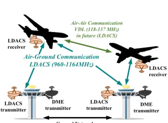
The Air traffic management (ATM) system handles all the communication between the ground terminals, aircrafts in airspace as well as between the aircrafts and ground terminals. Over the years, the air conveyance has increased immensely, and the current aeronautical communication system is reaching its capacity limit in high-density areas like Europe and the USA. In 2002, the International Civil Aviation Organization (ICAO) realized the need to improve the existing ATM system. The modernization of the ATM system is currently pursued by the Next Generation Air Transportation System (NextGen) and Single European Sky ATM Research (SESAR) in the USA and Europe respectively. They are working on the Future Commu-nication Infrastructure (FCI) system to meet the exponentially increasing air-traffic and support a wide variety of services and applications [1–3]. It consists of several communication data links between satellite stations, aircraft and ground terminals. Such FCI system is also used for other communications, navigation, and surveillance (CNS) applications. In this work, we mainly focus on the air-to-ground communication (A2GC) link which is the most crucial data link within the FCI, and it is shown in Fig. 1.
The A2GC has evolved tremendously in recent years. The first voice-based air to ground communication was deployed in the 1940s, used analog modulation scheme. To further increase
Air-Ground Communication LDACS (960-1164MHz) Air-Air Communication VDL (118-137 MHz) in future (LDACS) Ground Network LDACS transmitter DME transmitter LDACS
transmitter transmitterDME LDACS
receiver
LDACS receiver
Fig. 1. Air-to-Ground communication data link of the LDACS with DME interference.
the throughput and robustness of the system, the digitization of A2GC system was done in 1990s [2]. This digital A2GC link was deployed in the VHF band (118-137 MHz) and hence, referred to as VHF Data Link (VDL). It is currently used in the A2GC and air-to-air communications [2–5]. In the last decade, the air traffic has increased significantly leading to severe congestion in the VHF band. Furthermore, the existing system cannot support high-speed multimedia services due to limited bandwidth [6].
To meet the emergent demand of communication capacity, L-band (960-1164 MHz) has been allocated for the A2GC link in 2007 and referred to as L-band digital aeronautical communication system (LDACS). The LDACS is expected to be deployed in multiple 1 MHz vacant frequency bands between adjacent legacy distance measuring equipment (DME) channels [7]. The first version of the LDACS is based on the orthogonal frequency-division multiplexing (OFDM) and frequency-division duplex (FDD). Due to the rectangular fil-tering in the time domain, OFDM has very high side lobe atten-uation; hence, high interference with the adjacent legacy user leads to the limited transmission of the bandwidth of 498 KHz and therefore, less than 50% spectrum utilization. This opens the opportunity to explore the other candidate waveforms as an alternative to the OFDM based LDACS. Recently, we proposed reconfigurable filtered OFDM based LDACS (Ref-OFDM) which can adapt the transmission bandwidths on the fly and uses a single variable digital filter for all the different transmission bandwidths [8, 9]. This enables wider transmis-sion along with the multiple narrowband communications to fulfill the spectrum requirement for futuristic services and
support multimedia data. Via theoretical and simulation results, we show that proposed LDACS offers superior performance in terms of power spectral density (PSD) and bit-error-rate (BER) without compromising significantly on the complexity [8, 9]. This paper aims to support our claims via experimental results in the real radio environment. The main contributions of the paper are:
1) We develop an experimental testbed using three Na-tional Instrument (NI) USRP-2922 and VERT900 an-tennas for the deployment of the proposed Ref-OFDM based LDACS between two DME channels. Among three, one USRP is used for DME transmission as well as reception while the other two USRPs are used as LDACS transmitter and receiver, respectively.
2) The performance of the proposed Ref-OFDM based LDACS is compared with the existing LDACS in terms of interference (PSD) to the legacy DME channels, bit error rate, and the throughput achieved. For illustration, we consider two transmission bandwidths: (1) 498 KHz and (2) 732 KHz.
3) We analyze the performance by varying the parameters related to LDACS/DME transmitter and a receiver like 1) Distance, 2) Altitude, and 3) DME antenna gain. The rest of the paper is structured as follows. Section II gives a brief overview of the proposed Ref-OFDM based LDACS transceiver. The developed USRP testbed for LDACS deployment is presented in section III followed by the exper-imental results in section IV. Section V concludes the paper.
II. REF-OFDMBASEDLDACS TRANSCEIVER With the growing demand for air traffic, flight safety and good signal transmission is a major goal for the future A2GC. To fulfill the spectrum requirements, we have recently proposed an alternative to OFDM based LDACS referred to Ref-OFDM based LDACS protocol in [9]. In this section, a brief overview is provided for better understanding of the proposed testbed.
Due to the very high out of band emission, the existing OFDM based LDACS uses 498 KHz transmission bandwidth out of 1 MHz spectral gap between two adjacent DME channels which leads to more than 50% of spectrum wastage. The proposed Ref-OFDM based LDACS uses a bandwidth reconfigurable fixed coefficient multi-band linear phase FIR filter in the time domain, in which a single prototype filter can accommodate different transmission bandwidths. The proposed Ref-OFDM based LDACS has very less power in side lobes; hence, the interference with the adjacent DME channels is also less; this leads to the increase in the transmission bandwidth.
Also, because of the side lobe filtering, there is no need for guard bands. Therefore, it provides higher throughput compared to the existing one. The Ref-OFDM enables a transmission in multiple narrowband and allows to switch the transmission bandwidths on the fly.
A new frame structure protocol for Ref-OFDM based LDACS using the standard 128 point FFT size and 9.76 KHz subcarrier spacing is proposed in [9], which can transmit in 186- 732 KHz bandwidth range, The detailed description of the frame structure for the proposed Ref-OFDM is discussed in [9]. The bandwidth reconfigurable filter is designed using Coefficient Decimation factor (CDM) and improved CDM (ICDM) method. In this method, a baseband bandpass proto-type filter F(ejωc) is designed with the cut-off frequency ω
c.
The filter coefficients are obtained using the Parks-McClellan optimal FIR filter design method. The CDM generates a low pass filter response having the cut-off frequency as Dωc
where D ∈ {1, 2, 3..} by keeping only the Dth coefficients
unchanged and discarded the remaining coefficients. Similarly, the ICDM filter generates high pass filter response of cut-off frequency 1 − Dωc, from which low pass response can be
easily obtained using the appropriate delayed version of the input signal. In the ICDM method, every Dth coefficient are kept with a sign reversal of every other coefficient, and the remaining coefficients are discarded.
The block diagram of the proposed Ref-OFDM based LDACS is shown in Fig. 2. As per the LDACS specifica-tions [10], the LDACS randomizer first randomizes the input bitstream according to the randomizer sequence and then the randomized data is encoded by convolutional or Reed Solomon encoder. The output bits are then converted to symbols using modulator by selecting the appropriate modulation scheme such as QPSK, 16 QAM, 64 QAM. These symbols are then mapped to the subcarriers according to the LDACS frame structure followed by the conventional IFFT and cyclic prefix (CP) addition. The output of the CP addition is filtered using the proposed bandwidth reconfigurable digital filter; the filtered data is appropriately up sampled and converted to the RF center frequency and transmitted over the air. The signal is then down-converted to the same localized baseband frequency and filtered using the same filter at the receiver. Similar and reverse operations are performed at the receiver.
III. USRP TESTBED FORLDACS
In this section, we present experimental testbed using Uni-versal Software Radio Peripheral (USRP) for the deployment of the LDACS. USRP is a tunable transceiver from NI and is widely used for prototyping wireless communication systems.
Modulator Channel Encoder LDACS1 Randomizer 128-IFFT and CP Addition I/P LDACS transmitter USRP Subcarrier Mapping Reconfigurable Multi-band filter h[n] (a) Zero Forcing Equalizer Channel Estimation Pulse blanking
and 128-FFT Demodulation Decoding LDACS receiver USRP Reconfigurable Multi-band filter h[n] O/P (b) Fig. 2. Block diagram of the proposed Ref-OFDM based LDACS transceiver.
TABLE I. PARAMETERS OF TRANSMITTER AND RECEIVERUSRP
Parameters Transmitter Receiver Carrier Frequency 985 MHz 985 MHz IQ Sampling Rate 1.1 MHz 1.1 MHz LDACS antenna gain 2dB 2dB DME antenna gain 2dB/10dB -Acquisition Duration NA 1s
The Proposed testbed consists of three National Instrument (NI) USRP-2922 and VERT900 antennas as shown in Fig. 3. One USRP is used for DME transmission as well as reception while other two USRPs are used as LDACS transmitter and re-ceiver, respectively. Several baseband signal processing blocks of the transceiver are realized using the LabView environment from NI.
Fig. 3. USRP based testbed for LDACS.
A. LDACS Transmitter
To implement the inlay approach of deployment, the pro-posed Ref-OFDM based LDACS signal is transmitted at the carrier frequency of 985 MHz with the IQ sampling rate of 1.1 MHz. The transmission has been performed for the variable bandwidths ranging from 186-732 KHz using 128 points IFFT with 9.76 KHz sub-carrier spacing.
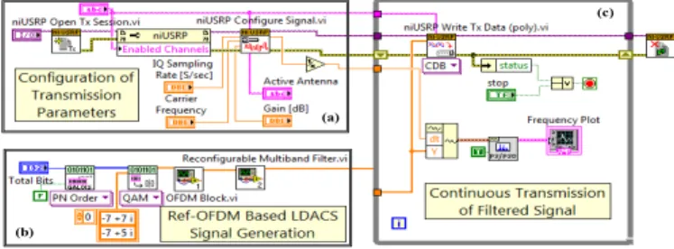
The LDACS transmitter realization is shown in Fig. 4, consists of three subsystems: (a) the first subsystem sets the transmission parameters such as carrier frequency, antenna gain, IQ sampling rate, and transmission antenna port, (b) the second subsystem is the LDACS transmitter which first generates the random bits and then modulates them by select-ing an appropriate modulation scheme. The “OFDM Block.vi ” performs all the LDACS transmitter operations as discussed in section II. The synchronization symbols are added to the LDACS frame for the synchronization at the receiver followed by the filtering operation performed using the “Reconfigurable Multiband Filter.vi ”, (c) The Third subsystem continuously transmits the filtered data over the desired carrier frequency via LDACS USRP transmitter.
(a)
(b)
(c)
Fig. 4. Implementation of Ref-OFDM based LDACS transmitter in the LabView environment
B. DME transmitter
The DME is a navigation legacy system composed of Gaussian shaped pulse pairs having 1 MHz of spectral gap and variance of4.5 ∗ 1011. More details of the DME specifications
and its time and frequency domain representation is provided in [8].
Similar to the LDACS transmitter, the DME transmitter model as shown in Fig 5 comprises three sub-blocks (a) the first sub-block configures the USRP parameters as mentioned in the table I for the DME transmission, (b) the second sub-block is dedicated for the DME signal generation. This includes two Gaussian monopulse generator blocks which gen-erate the Gaussian pulses with the center frequencies of 984.5 MHz and 985.5 MHz. These monopulses are later combined to achieve the DME signal of Gaussian pulse pair, and at every transmission, it transmits 2700 pulse pairs per second, (c) the last sub-block is realized to continuously transmit the DME signal over the air.
(a)
(b)
(c)
Fig. 5. Implementation of DME transmitter in the LabView environment
C. LDACS Receiver
The LDACS signal is then received by the LDACS receiver USRP, tuned at 985 MHz to receive the transmitted signal at IQ sampling rate of 1.1 MHz. However, due to a mismatch between the oscillator frequency at the transmitter and receiver USRPs, additional synchronization is needed at the receiver (see details in Fig. 6). In this work, to identify the beginning of each frame, the received signal is frame synchronized by determining the cross-correlation between the received signal and the known synchronization symbols added in the LDACS frame at the transmitter. The signal is then processed from the maximum correlated value index. The proposed Ref-OFDM uses a matched reconfigurable filter at the receiver followed by fine synchronization to estimate time and frequency offsets. The fine synchronization is based on the correlation of cyclic prefix of each OFDM symbol. After that, the channel is estimated using pilots followed by channel equalization via zero forcing method. In the end, the symbols are demodulated and decoded for subsequent performance analysis.
Fig. 6. Implementation of Ref-OFDM based LDACS receiver in the LabView environment
In addition to proposed LDACS, we have also realized ex-isting OFDM based LDACS along with additional windowing. We have skipped the details due to limited space constraints.
IV. HARDWAREEXPERIMENTALRESULTS
For experimental results and analysis, the parameters are considered as per LDACS specifications and are given in ta-ble II. We have done the comparison in terms of the PSD, BER and throughput for two different transmission bandwidths: 1) 498 KHz and 2) 732 KHz.
TABLE II. LDACSSPECIFICATIONS
Parameters Value
Total Bandwidth 1.1MHz
Transmitted Bandwidth any of the supported bandwidth (186-732 KHz)
Length of FFT 128
Sub-carrier spacing 9.76KHz
Used sub-carriers 18-74
Total Symbol duration 120µs
Modulation Scheme QPSK
CC encoder rate 0.5
RS encoder rate 0.9
A. Power Spectral Density Analysis
The PSD performance comparison of the existing LDACS and the proposed LDACS is shown in Fig. 7 (a) and (b) for the considered 498 KHz and 732 KHz transmission bandwidth respectively. The existing LDACS can only transmit up to 498 KHz due to the very high side lobe power creating the interference higher than the 40 dB tolerable limit of the DME signal. It can be observed from the Fig. 7 (a) and (b) that the proposed LDACS has approximately 35 dB less out of band (OOB) emission due to the reconfigurable filtering, hence, the less adjacent DME channel interference. This allows the proposed LDACS to achieve higher transmission bandwidth up to 732 kHz, which leads to relatively 25% of the spectral improvement than the existing one.
-5.5 -4 -2.5 -1 0.5 2 3.5 5 5.5 Frequency (MHz) 105 -100 -80 -60 -40 -20 0 PSD (dB) Existing LDACS Proposed LDACS DME signal (a) -5.5 -4 -2.5 -1 0.5 2 3.5 5 5.5 Frequency (MHz) 105 -100 -80 -60 -40 -20 0 PSD (dB) DME signal Existing LDACS Proposed LDACS (b)
Fig. 7. The PSD comparison for two different transmission bandwidths, (a) 498 KHz, and (b) 732 KHz
B. Bit error Rate Analysis
Here, we compare the BER performance of the proposed LDACS with the existing LDACS in the presence of the DME interference. The LDACS signal received at the receiver USRP is presented in the Fig 8 for two different transmission bandwidths (1) 498 KHz, and (2) 732 KHz. As we can observe that 732 KHz bandwidth accommodates very high DME interference, which consequently results in lower BER performance.
(a) (b)
Fig. 8. Signal received at LDACS receiver USRP: (a) 498 KHz, (b) 732 KHz.
Next, we discuss the detailed BER analysis by considering three scenarios (1) variable distance, (2) variable altitude, and (3) variable DME antenna gain.
1) Variable Distance: Here, the BER performance is ana-lyzed by varying the distance (D) between the LDACS/DME transmitter and the LDACS receiver considering 498 KHz and 732 KHz as the transmission bandwidths. We assume that DME and LDACS transmitter are located close to each
0 1000 2000 3000 4000 5000 6000 D (cm) 10-6 10-5 10-4 10-3 10-2 10-1 100
Bit Error Rate
Existing LDACS (LOS) Proposed LDACS (LOS) Existing LDACS (NLOS) Proposed LDACS (NLOS)
(a) 0 1000 2000 3000 4000 5000 6000 D (cm) 10-6 10-5 10-4 10-3 10-2 10-1 100
Bit Error Rate Existing LDACS (LOS)Proposed LDACS (LOS)
Existing LDACS (NLOS) Proposed LDACS (NLOS)
(b)
Fig. 9. The BER comparison for the variable distance between LDACS/DME transmitter and LDACS receiver (D) for two different transmission band-widths, (a) 498 KHz, and (b) 732 KHz
other resulting in worst possible interference. For all the distances, line of sight (LOS) and non-line of sight (NLOS) communications are examined. As shown in Fig. 9, the BER degraded with an increase in D and proposed LDACS offers better performance than existing LDACS. It can be observed that BER gets worse for NLOS scenario as well as for higher transmission bandwidth.
2) Variable Altitude and DME antenna gain: Next, we analyze the BER performance by varying the altitude of the LDACS receiver keeping the LDACS/DME transmitter at the same fixed level. For all the heights, two values of the DME antenna gain (1) 2dB and (2) 10dB are considered. When the LDACS receiver is placed at a higher altitude, the received LDACS signal power reduces while the interference power remains the same. Thus the BER performance degrades as shown in Fig. 10. At the same time, with the increase in DME antenna gain (from 2dB to 10dB) the DME interference power dominates the LDACS transmitted signal power which causes in higher BER.
The proposed LDACS has better BER performance than the existing one for all the considered scenarios makes it a very enticing replacement to the existing W-OFDM based LDACS.
0 100 200 300 400 500 600 700 H (cm) 10-5 10-4 10-3 10-2 10-1 100
Bit Error Rate Existing LDACS (2dB)Proposed LDACS (2dB)
Existing LDACS (10dB) Proposed LDACS (10dB) (a) 0 100 200 300 400 500 600 700 H (cm) 10-5 10-4 10-3 10-2 10-1 100
Bit Error Rate
Existing LDACS (2dB) Proposed LDACS (2dB) Existing LDACS (10dB) Proposed LDACS (10dB)
(b)
Fig. 10. The BER comparison for the variable altitude of the LDACS receiver and LDACS / DME transmitter(H) with DME antenna gain of 2dB and 10dB for two different transmission bandwidths, (a) 498 KHz, and (b) 732KHz
C. Throughput Analysis
In this subsection, the achieved throughput by the proposed LDACS with the existing LDACS is compared and analyzed in the presence of the DME interference. As it can be observed from the PSD results (Fig. 7), that the proposed LDACS has very less interference with the adjacent DME channel, hence it does not require any guard bands for interference reduction.
This helps to achieve higher throughput for the proposed Ref-OFDM based LDACS over the variable distances and altitudes considered above. The achieved throughput values are presented in table III. When the distance and altitude are higher, we get less throughput because of the lower signal power. High throughput performance also supports a higher data rate, which is an essential requirement for future A2GC. TABLE III. THROUGHPUT ACHIEVED FOR VARIABLE DISTANCE AND
ALTITUDE Distances (cm) Throughput (Mbps) (existing) Throughput (Mbps) (proposed) Height (cm) Throughput (Mbps) (existing) Throughput (Mbps) (proposed) 5 4.2123 5.0125 10 4.9247 5.5475 182 3.7215 4.8245 90 1.5894 2.3245 450 2.2171 4.0548 188 0.5734 0.7581 945 0.7818 2.9002 493 0.1995 0.3883 2450 0.0567 1.7951 766 0 0 4205 0 0 - - -5940 0 0 - - -V. CONCLUSION
In this paper, we have developed an experimental testbed for the proposed Ref-OFDM based LDACS and compared the PSD, BER and throughput performance with the existing LDACS. The hardware setup includes three NI USRPs for LDACS transmitter, LDACS receiver, and DME transmitter. The signals are transmitted using three VERT 900 antennas. For the performance analysis, different scenarios related to LDACS transmitter/receiver and DME transmitter are consid-ered such as variable distance, variable altitude, LOS, NLOS, and variable DME antenna gain. The proposed Ref-OFDM based LDACS provides nearly 35 dB less OOB emission and offer better BER/Throughput in all the above-considered scenarios which makes it an alluring substitute to the existing LDACS.
REFERENCES
[1] M. Schnell, U. Epple, D. Shutin and N. Schneckenburger, “LDACS: future aeronautical communications for air-traffic management,” in IEEE
Communications Magazine,vol. 52, no. 5, pp. 104-110, May. 2014. [2] S. Gligorevic, U. Epple, and M. Schnell “The LDACS1 physical layer
design,” INTECH Open Access Publisher, 2011.
[3] Sajatovic M., Haindl B., Ehammer M., Grupl T., Schnell M., Epple U., and Brandes S., “L-DACS1 System Definition Proposal: Deliverable D2,” in Technical Report, Eurocontrol, no. 1.0, Feb 2009.
[4] M. Schnell, N. Franzen and S. Gligorevic, “L-DACS1 laboratory demon-strator development and compatibility measurement set-up,” 29th Digital
Avionics Systems Conference,Salt Lake City, UT, 2010, pp. 3.E.3-1-3.E.3-11.
[5] U. Epple and M. Schnell, “Overview of legacy systems in L-band and its influence on the future aeronautical communication system LDACS1,” in
IEEE Aerospace and Electronic Systems Magazine,vol. 29, no. 2, pp. 31-37, Feb. 2014.
[6] N. Neji, R. de Lacerda, A. Azoulay, T. Letertre and O. Outtier, “Survey on the Future Aeronautical Communication System and Its Development for Continental Communications,” in IEEE Transactions on Vehicular
Technology,vol. 62, no. 1, pp. 182-191, Jan. 2013.
[7] N. Schneckenburger, N. Franzen, S. Gligorevic and M. Schnell, “L-band compatibility of LDACS1,” IEEE/AIAA 30th Digital Avionics Systems
Conference (DASC),pp. 1-11, Seattle, USA, Oct. 2011.
[8] N. Agrawal, S. J. Darak, and F. Bader, “Reconfigurable filtered OFDM waveform for next generation air-to-ground communications,” IEEE/AIAA
36th Digital Avionics Systems Conference (DASC),pp. 1-7, St. Petersburg, USA, Sept. 2017.
[9] N. Agrawal, S. J. Darak, and F. Bader, “New Spectrum Efficient Reconfig-urable Filtered-OFDM Based L-band Digital Aeronautical Communica-tion System,”in IEEE TransacCommunica-tions on Aerospace and Electronic System. [10] S. Brandes, et al. “Physical layer specification of the L-band Digital Aeronautical Communications System (L-DACS1), ” IEEE Integrated
Communications, Navigation, and Surveillance Conference, pp. 1-12, Arlington, USA, May. 2009.