HAL Id: hal-01008542
https://hal.archives-ouvertes.fr/hal-01008542
Submitted on 6 Nov 2019HAL is a multi-disciplinary open access archive for the deposit and dissemination of sci-entific research documents, whether they are pub-lished or not. The documents may come from teaching and research institutions in France or abroad, or from public or private research centers.
L’archive ouverte pluridisciplinaire HAL, est destinée au dépôt et à la diffusion de documents scientifiques de niveau recherche, publiés ou non, émanant des établissements d’enseignement et de recherche français ou étrangers, des laboratoires publics ou privés.
Numerical modeling of 3 point bending test of a
reinforced concrete beam using a second gradient theory
Gwendal Jouan, Panagiotis Kotronis, Frédéric Collin
To cite this version:
Gwendal Jouan, Panagiotis Kotronis, Frédéric Collin. Numerical modeling of 3 point bending test of a reinforced concrete beam using a second gradient theory. 6th European Congress on Computational methods in applied sciences and and Engineering (ECCOMAS 12), Sep 2012, Vienna, Austria. �hal-01008542�
Vienna, Austria, September 10-14, 2012
NUMERICAL MODELING OF A 3 POINT BENDING TEST OF A
REINFORCED CONCRETE BEAM
USING A SECOND GRADIENT THEORY
G. Jouan1,2, P. Kotronis1, and F. Collin2
1
LUNAM Université, Ecole Centrale de Nantes, Université de Nantes, CNRS Institut de Recherche en Génie Civil et Mécanique (GeM)
1 Rue de la Noë, F-44321 Nantes, France gwendal.jouan@ec-nantes.fr panagiotis.kotronis@ec-nantes.fr
2
Département Argenco – Université de Liège Institut de mécanique et Génie Civil, Bât. 52 1 Chemin des chevreuils, B-4000 Liège 1, Belgium
f.collin@ulg.ac.be
Keywords:three point bending test, localization, second gradient, reinforced concrete
Abstract. Being a quasi-brittle material, concrete exhibits a strain softening behavior that
cannot be reproduced with classical continuum mechanics models. To regularize the problem, an internal length should be introduced. Several ways to do so have been proposed in the lit-erature. One way is the so called local second gradient model. It is a local theory as it intro-duces the internal length by enriching the kinematical description of the continuum adding higher order gradients of the displacement according to the work of Cosserat [8], Toupin [18], Mindlin [19] and Germain [9,10]. The model has been developed by Chambon et al. [11,12] and has this far been used mainly to reproduce the behavior of soils. It is here ap-plied for the first time to a reinforced concrete beam subjected to a 3 point bending test.
G. Jouan, P. Kotronis, and F. Collin
2
1 INTRODUCTION
Strain localization in quasi-brittle materials, or more generally in materials exhibiting strain softening is a well-known problem [1] [2] [3]. It is a phenomenon that can be clearly observed in experimental tests, and yet cannot be modeled with classical continuum mechan-ics models. Analytically, the solution is a crack with zero energy dissipation [4]; numerically, it leads to a pathological mesh dependency. These shortcomings are due to the lack of an in-ternal length in the continuum model.
Several ways of introducing an internal length have been proposed. Non local integral models were first formulated by Pijaudier-Cabot et al. [4] and applied to damage theory. The gradient models of Aifantis [6] enrich the conventional plasticity and damage theories with gradients of the internal variables. This type of model can be shown to be equivalent to the integral type models. More recently, strain localization due to damage has been treated using the thick level set approach [7].
A rather natural way of introducing (indirectly) a length parameter in a continuum model is to account for the microstructure of the material. The general class of so called microstructured models or higher order continuum models allows for the description of the kinematics of the microstructure by using an additional tensor in the displacement field. Higher order continuum theories can be traced back to the works of the Cosserat brothers [8] and have been generalized and properly formulated by Germain [9] [10] using the method of virtual power.
The local second gradient model developed by Chambon et al. can be seen as a particular case of a higher order continua and has been used to regularize problems involving localiza-tion in geomaterials [11,12]. It is hereafter used to model a three point bending test of a rein-forced concrete beam.
2 THE SECOND GRADIENT MODEL
2.1Theoretical framework
As detailed in the seminal work of Germain, using the virtual power method one can choose a field of virtual displacements to describe the proper kinematics of the continuum (including its microstructure). The internal stresses, limit conditions and equilibrium equa-tions appear naturally as long as the linear form representing the virtual power is correctly de-fined and that it respects the principle of material independence.
Following this, if we choose the virtual displacement field as the “field of continuous and continuously differentiable velocities”, then the principle of virtual work yields:
∗ + Σ ,
∗ Ω − ∗ Ω − ∗+ ∗ = 0 (1)
Where ui is the displacement field, Dij is the symmetric part of its gradient, σij is the macro
stress (conjugate of the first gradient of the velocity field) and Σijk is a double stress
(conju-gate of the second gradient of the velocity field). Gi is the classical body force, pi is a contact
force and Pi a double contact force. Dui refers to the normal derivative: Dui = nk ui/ xk.. Here
and henceforth * denotes a virtual quantity.
The equilibrium equations and boundary conditions are given by:
3
− Σ − Σ − Σ + Σ − Σ = (3)
Σ = (4)
Where Dq/Dxj is the tangential derivative.
Here we suppose that the model uses two constitutive equations, one linking the macro stress to the first gradient of the displacements and the other linking the double stress to the second gradient of the displacements. The two equations are also supposed to be decoupled. The first gradient law can be any classical constitutive law (involving or not damage, plastici-ty etc…). The constitutive laws can be written in rate form as:
= ! " (5.1)
Σ = # $% ,$% (5.2)
If the second gradient law is an isotropic elastic one, the general form of the constitute law involves five material parameters.
& ' ' ' ' ' ' ' ' () *** ) ** ) * * ) * ) ** ) * ) * ) +, , , , , , , , -= & ' ' ' ' ' ' (.* /010 .*010 0 . / .*01 0 0 .*01 . / 0 . *01 0 0 ./0 0 .* . 1 0 . * 0 0 .* . 1 0 0 . 1 0 . * . 1 0 0 . 1 .* 0 . 1 0 0 . 1 .* 0 0 .* 0 . 1 .* 0 ./0 0 0 .*01 0 . / .*01 0 0 .*01 . / 0 . *01 0 0 .* /01+, , , , , , -& ' ' ' ' ' ' ' ( *,** *,* *, * *, ,** ,* , * , + , , , , , , , -(6)
Where aijk…are functions of five material parameters a1, a2, a3, a4, and a5[19].
A particular form of this latter constitutive equation has been proposed by Chambon et al.[19] with a single modulus B (corresponding to a specific choice of the ai parameters).
The internal length does not appear explicitly in these equations. However, the analytical solution in a one-dimensional localization problem with a bilinear first gradient law of moduli
A1 and A2, exhibits a localized strain band with an internal length ls given by [13]:
2. ℎ 45−67 89 − :* ;<= = −5−66 2. >* 5−67 :;? (7)
It is shown that the internal length ls is a function of the ratio B over A2.
The use of the second gradient model allows for the proper representation of strain locali-zation but it does not restore the uniqueness of the solution. For a one-dimensional tension test or a biaxial compression test, the number of bands and their positions can vary [14]. This is in accordance with experimental results which tend to be poorly reproducible when involv-ing strain localization.
2.2Numerical implementation
The second gradient of the displacements in the weak formulation of the problem necessi-tates the use of C1 elements in a finite element code. This can be avoided by introducing a new field vij imposed equal to the gradient of ui through the use of Lagrange multipliers [15].
G. Jouan, P. Kotronis, and F. Collin 4 ∗ + Σ @ , ∗ Ω − A B ∗− @∗C Ω − " = 0 (8.1) A∗ B − @ C Ω = 0 (8.2)
The problem is then discretized using a 9th node second gradient finite element: 8 of the nodes are used for ui, 4 for vij and the central node for λij.
Figure 1: Second gradient finite element [15]
This element has been implemented in the finite element code Lagamine and the problem is solved using the classical Newton-Raphson method.
3 THE THREE POINT BENDING TEST
The experimental test was conducted on a reinforced concrete beam according to the speci-fications of the CEOS.FR benchmark. The beam is of thickness b=200mm, height h=500mm and 5000mm span (see: figure 2). It was subjected to a cyclic controlled load.
Figure 2: Reinforced concrete beam dimensions [17] Strains were measured with gauges placed as indicated on figure 3.
5
Figure 3: Location of strain gauges [17]
4 MODELISATION OF THE BENDING TEST
The bending test is modeled as a two dimensional problem using the 9 node finite element described above. Two meshes have been used for the simulations. The first mesh consists of 5180 elements, 4148 of which are second gradient elements representing concrete and 1032 truss elements representing the horizontal reinforcement. The average size of the concrete el-ements for this mesh is of 0.02mx0.035m. The second mesh consists of 13494 elel-ements with an average size of 0.01mx0.017m for the concrete elements. Concrete and steel elements are supposed to be perfectly bonded. The end nodes at the bottom of the beam are blocked verti-cally; the right node at the bottom is also blocked horizontally.
Figure 4: Finite element meshes [15]
The concrete behavior is reproduced using the classical Mazars damage law [16]. The equivalent strain is defined as:
DEF =G〈D〉+:〈D〉+ (9)
Where 〈 〉K denote the positive part and : is the double dot product. The damage is sepa-rated in two parts Dt and Dc, one due to the tension, and one due to compression.
L= 1 − D 081 − 6D L< EF − 6LE −7LNDEF−D 0O (10.1) 2= 1 − D 081 − 6D 2< EF − 62E −72NDEF−D 0O (10.2)
Where εd0, Ac, At, Bc and At are material parameters provided in table 1:
E (GPa) εd0 At Bt Ac Bc β 37.2 9.10-5 0.7 6800 0.42 780 1.1
Table 1: Concrete material parameters
On the upper part where the loading is applied and at both supports at the bottom an elastic linear law is introduced to prevent from unwanted damage. An elasto-plastic law with iso-tropic hardening is used for steel.
G. Jouan, P. Kotronis, and F. Collin
6 Upper trusses
E (GPa) σ (MPa) Area (cm²) 195 466 16.085 (2HA32)
Lower trusses
E (GPa) σ (MPa) Area (cm²)
195 466 1.0053(2HA8)
Table 2: Steel material parameters
The second gradient constitutive law for concrete depends on the elastic modulus B taken equal to 1.5.MN.
5 RESULTS
Overall, the numerical results are in good accordance with the experimental data. Figure 5 shows the numerical global force versus displacement at the center of the beam compared to the experimental results (note: for the experimental test the beam was loaded and unloaded cyclically whereas in the simulation the beam was loaded with a monotonic increasing dis-placement).
Figure 5: Numerical results Vs. Experimental data: Force-Displacement at the center of the beam The force displacement graph exhibits the classical reinforced concrete behavior in three stages: In the first stage, concrete and steel stay both in the elastic regime; then concrete starts to damage and the slope on the force displacement curve slightly changes. Finally, steel enters in the plastic phase and the second change in the slope appears. The final slope of the numeri-cal simulation doesn’t match the experimental one, but results can be improved by doing a parametrical study on the influence of the elastic modulus B.
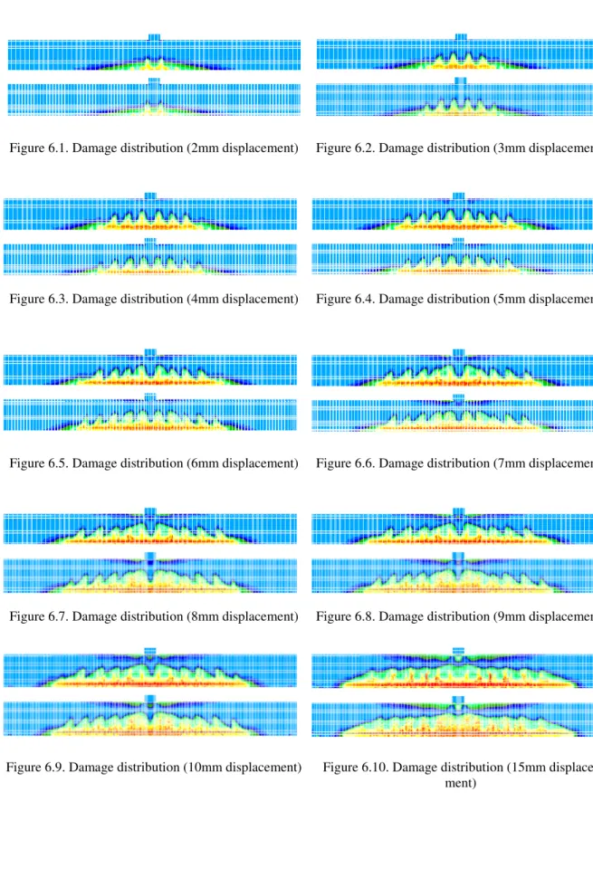
Figure 6 shows the pattern of the damage variable in concrete for different stages of load-ing and for the two meshes.
0 50000 100000 150000 200000 250000 300000 350000 -0.08 -0.07 -0.06 -0.05 -0.04 -0.03 -0.02 -0.01 0 F o rc e ( N ) vertical displacement (m) experimental numerical
7
Figure 6.1. Damage distribution (2mm displacement) Figure 6.2. Damage distribution (3mm displacement)
Figure 6.3. Damage distribution (4mm displacement) Figure 6.4. Damage distribution (5mm displacement)
Figure 6.5. Damage distribution (6mm displacement) Figure 6.6. Damage distribution (7mm displacement)
Figure 6.7. Damage distribution (8mm displacement) Figure 6.8. Damage distribution (9mm displacement)
Figure 6.9. Damage distribution (10mm displacement) Figure 6.10. Damage distribution (15mm displace-ment)
G. Jouan, P. Kotronis, and F. Collin
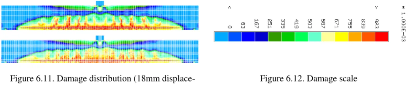
8 Figure 6.11. Damage distribution (18mm
displace-ment)
Figure 6.12. Damage scale
The damage pattern develops with sudden “peaks” which experimentally correspond to developing cracks. The crack opening is not modeled directly in this simulation as the dis-placement field remains continuous, but it can be calculated from the damage model either through energetic equivalence or by simply measuring the jump in displacements between two points located on the opposite sides of the damaged zone. This obviously works only when the damaged bands are clearly separated. The width and separation of the damage bands can be controlled by changing the internal length, which in our case would mean changing the slope of either or both the first gradient and second gradient constitutive laws.
For concrete bending tests, non-local damage models which define an equivalent strain by averaging over a certain distance lc may develop damage on the upper compressed part of the
beam even when the local strain is not high enough to trigger damage. This is due to the aver-aging over an area. There is no such problem with this model as all the variables are local, including the equivalent strain.
6 CONCLUSIONS
A second gradient model has been used to model the three point bending test of a rein-forced concrete beam. The results show that the model is able to reproduce the force-displacement curve obtained experimentally. The damage localizes into bands and their width is controlled by the model parameters. The uniqueness of the solution is however not restored as shown by the results obtained with two different meshes. In these two cases the bands are of the same size but their numbers can vary (figure 6). Being a local theory, the second gradi-ent method avoids the limitations caused by the use of a non-local definition of the equivalgradi-ent strain used in the non-local damage theory.
These results are encouraging and represent the first steps toward a wider use of the local second gradient method for concrete structures.
REFERENCES
[1] R. Hill, J.W. Hutchinson: Bifurcation phenomena in the plane tension test. Journal of
the Mechanics and Physics of Solids, 23 (1975), 239-264.
[2] J.R. Rice: The Localization of plastic deformation. Theoretical and Applied Mechanics,
Proceedings of the 14th International Congress on Theoretical and Applied Mechanics,
1 (1976), 207-220
[3] J.W. Rudnicki, J.R. Rice: Conditions for the localization of deformation in pressure-sensitive dilatant materials. Journal of the Mechanics and Physics of Solids, 23 (1975), 371-394.
9
[4] G. Pijaudier-Cabot, Z. Bažant: Nonlocal damage theory. Journal of Engineering
Me-chanics, 113 (1987), 1512–1533.
[5] Z. Bažant, T. Belytschko, T.-P. Chang: Continuum theory for Strain-Softening. Journal
of Engineering Mechanics, 110 (1984), 1666-1692.
[6] E. Aifantis: On the microstructural origin of certain inelastic models. Journal of
Engi-neering Materials and Technology, 106 (1984), 326-330.
[7] N. Moës, C. Stolz, N. Chevaugeon: A level set based model for damage growth: The
thick level set approach. International Journal for Numerical Methods in Engineering, 86 (2011), 358-380.
[8] E. Cosserat, F. Cosserat: Théorie des corps déformables. A. Hermann et Fils, 1909. [9] P. Germain: La méthode des puissances virtuelles en mécanique des milieux continues:
Première partie : théorie du second gradient. Journal de Mécanique, 12 (1973), 235-274. [10] P. Germain: The method of virtual power in continuum mechanics. Part 2.
Microstruc-ture. Journal of Applied Mathematics, 25 (1973), 556-575.
[11] R. Chambon, D. Caillerie, T. Matsushima: Plastic continuum with micro-structure, local second gradient theories for geomaterials: localization studies. International Journal of
Solids and Structures, 38 (2001) 8503–8527.
[12] T. Matsushima, R. Chambon, D. Caillerie: Second gradient models as a particular case of microstructured models: a large strain finite elements analysis. Comptes Rendus de
l’Académie des Sciences de Paris, 328 (2000) 179–186.
[13] R. Chambon, D. Caillerie, N. El Hassan: One-dimensional localization studied with a second grade model. European Journal of Mechanics and Solids, 17 (1998) 637–656. [14] P. Bésuelle, R. Chambon, F. Collin: Switching deformation modes in post-localization
solutions with a quasibrittle material. Journal of Mechanics of Materials and Structures, 1 (2006) 1115–1134.
[15] T. Matsushima, R. Chambon, D. Caillerie: Large strain finite element analysis of a local second gradient model: application to localization. International Journal for Numerical
Methods in Engineering, 54 (2002) 179–186.
[16] J. Mazars : Application de la mécanique de l’endommagement au comportement non li-néaire et à la rupture du béton de structure, Thèse de doctorat d’état de l’Université
Pa-ris VI (1984).
[17] Jason, L. Réponse au benchmark statique monotone du projet national CEOS.FR. Rap-port CEA SACLAY, DM2S/SEMT/LM2S, RapRap-port ANR MEFISTO, 2008.
[18] R.A. Toupin: Elastic materials with couple-stresses. Archive for rational mechanics and
analysis 11 (1962), 385-414.
[19] R.D. Mindlin: Second gradient of strain and surface tension in linear elasticity.
![Figure 2: Reinforced concrete beam dimensions [17]](https://thumb-eu.123doks.com/thumbv2/123doknet/11324512.283000/5.892.294.622.325.456/figure-reinforced-concrete-beam-dimensions.webp)
![Figure 4: Finite element meshes [15]](https://thumb-eu.123doks.com/thumbv2/123doknet/11324512.283000/6.892.142.777.494.612/figure-finite-element-meshes.webp)