HAL Id: hal-00862667
https://hal-univ-rennes1.archives-ouvertes.fr/hal-00862667
Submitted on 17 Sep 2013
HAL is a multi-disciplinary open access
archive for the deposit and dissemination of
sci-entific research documents, whether they are
pub-lished or not. The documents may come from
teaching and research institutions in France or
abroad, or from public or private research centers.
L’archive ouverte pluridisciplinaire HAL, est
destinée au dépôt et à la diffusion de documents
scientifiques de niveau recherche, publiés ou non,
émanant des établissements d’enseignement et de
recherche français ou étrangers, des laboratoires
publics ou privés.
Performance and Radiation Patterns of A
Reconfigurable Plasma Corner-Reflector Antenna
Mohd Taufik Jusoh Tajudin, Mohamed Himdi, Franck Colombel, Olivier
Lafond
To cite this version:
Mohd Taufik Jusoh Tajudin, Mohamed Himdi, Franck Colombel, Olivier Lafond.
Performance
and Radiation Patterns of A Reconfigurable Plasma Corner-Reflector Antenna. IEEE Antennas
and Wireless Propagation Letters, Institute of Electrical and Electronics Engineers, 2013, pp.1.
�10.1109/LAWP.2013.2281221�. �hal-00862667�
Abstract—A novel reconfigurable plasma corner reflector
antenna is proposed to better collimate the energy in forward direction operating at 2.4GHz. Implementation of a low cost plasma element permits beam shape to be changed electrically. The maximum measured gains are 5.7dBi, 10.8dBi and 10.5dBi for the omnidirectional, single and double beam shapes respectively.
Index Terms—Corner reflector antenna, plasma corner
reflector antenna, plasma antenna, reconfigurable antenna, reconfigurable plasma antenna.
I. INTRODUCTION
INCE many years ago, reflecting surfaces have been used widely in order to steer a beam in the forward direction in antenna systems. Basic reflector antenna that uses reflecting surfaces is known as corner-reflector antenna (CRA). The CRA was first introduced in 1940 by John D. Kraus [1] and known to have about 9-14 dBi gain. Most of CRA use classical antennas such as dipole as a feeder and two flat sheets intersecting at an angle (known as included angle) as the reflector elements. However the simplest design of CRA will suffer from wind effect if it is mounted in the open space. Therefore, one way to eliminate this problem is by replacing the flat surfaces with wire grids. Indeed, its performance is comparable with flat reflecting sheets. Basic guide to design CRA is accessible and well documented in many antenna reference books such as in [2], [3]. Other than forwarding plane wave, circularly polarized CRA was first introduced in [4]. The earliest study on the effect of several lengths and widths of reflecting surfaces on CRA radiation pattern has been carried out in [5]. In addition, many techniques to increase gain of CRA were proposed in [6-8]. A quad CRA in
This work was supported in part by the Malaysian Ministry of Education (MOE), formerly known as Ministry of Higher Education (MOHE).
Mohd Taufik Jusoh (mohd-taufik.jusoh-tajudin@univ-rennes1.fr), Olivier Lafond (olivier.lafond@univ-rennes1.fr), Franck Colombel (franck.colombel@univ-rennes1.fr) and Mohamed Himdi (mohamed.himdi@univ-rennes1.fr) are with are with the Institute of Electronics and Telecommunications of Rennes, UMR CNRS 6164, University of Rennes 1, Campus de Beaulieu, Rennes Cedex 35042, France.
Mohd Taufik Jusoh is also with the Department of Electrical and Electronic, Faculty of Engineering, National Defence University of Malaysia, Kem Sungai Besi, 57000 Kuala Lumpur, Malaysia (taufik@upnm.edu.my).
[9] and reactively controlled CRA in [10] were proposed to work at 2.4GHz. A mechanical approach of achieving variable beamwidth by changing the included angle of CRA was proposed in [11]. The design was simulated and measured with the feed-to-vertex spacing is fixed. Generally, beam shaping and beam steering by using plasma reflector are very promising profiles, especially ability of plasma to be reconfigured electrically which is impossible to be done by metal elements.
Unlike, parabolic reflectors, CRAs are uncomplicated in design since they eliminate the crucial part of focal point for a driven dipole and the action of the reflector is not critical as to frequency [1]. In fact, the parabolic reflectors provide slight or no improvement over CRA of comparable size in terms of performance [1]. John D. Kraus claimed that by changing the feed-to-vertex spacing, s with the same included angle, 1 the beam can be varied from single beam into dual beams. However, with this approach, the s needs to be altered mechanically. For that reason, as proposed in this letter, instead of changing the s, an electrical switchable beam shape is implemented. There is no need to vary the location of the feeder since this method exploiting plasma characteristics [12], [13]. Only by energizing and de-energizing several plasma elements in seconds, omnidirectional pattern can be easily transformed into several forward beams. In other antenna design [14], an idea of using plasma posts for reconfigurable disc antenna was theoretically investigated.
To the best of our knowledge, there is no realization of CRA at any frequency band that has used other than metallic materials as an element except in a simulation proposed in [15]. Hence, this letter is aimed to present simulation and experimental results in order to verify the performance and the radiation patterns of a novel reconfigurable plasma CRA. Three different beam shapes are offered alternately, and the CRA is operating at 2.4GHz. The implementation of compact fluorescent lamps (CFL) has reduced the risk of complexity of impedance tuning which is vital when dealing with parasitic elements in designing antenna arrays. Other than antenna reconfigurability profile, reduced radar cross section (RCS) [16], [17], better gain, good cross-polarization, and high front to back ratio, the overall system is unique because it implements commercially available CFL [18] in order to stay considerably small, compact in size and low cost, if one compares to the elements used in [12] and assumed in [19].
Performance and Radiation Patterns of A
Reconfigurable Plasma Corner-Reflector
Antenna
Mohd Taufik Jusoh, Olivier Lafond, Franck Colombel, and Mohamed Himdi
Comparisons between simulated and measured results in the same configuration are discussed thoroughly in this letter. The simulations were run using finite-element-method-software, CST Suite [20].
II. PLASMA FORMULATION
The isotropic plasma is a dispersive material that has complex permittivity. The permittivity under low electron-neutral collision is given by (1) [12];
(
iv
)
p r−
−
=
ω
ω
ω
ε
1
2 (1) where 2r is the complex plasma permittivity, 3 is theoperating angular frequency [rad/s] and v is the electron-neutral collision frequency [Hz]. The 3p is the plasma angular
frequency [rad/s], and its value can be calculated as in (2) [12], [21]; 2 1 0 2
11
2
3
44
5
6
=
ε
ω
m
ne
p (2) where n is the electron density [m-3], e is the charge of electron [C], m is the electron mass [kg] and 20 is the freespace permittivity [F/m]. From (1), the 2r of the plasma will
vary if the 3p varies and the 3p can be altered by changing the
n as expressed in (2). In order to have the same behavior as a metal, the 3p of plasma must be higher enough than 3 (εr70).
v
p 2 0ω
ε
σ
=
(3) When the 3p is large enough compared to the v, the plasmaexhibits good electrical conductivity, 4 as given in (3) [12]. By varying 3p or v will give different values of 4 and hence the
characteristics of electromagnetic wave will be changed. III. SIMULATION AND MODELING
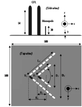
The CRA elements are made of series of CFLs which are coordinated in V arrangement (Fig. 1). Since the included angle is equals to 90° this CRA is also known as square-CRA [1-3]. The number of CFL elements used in simulation is depending on the length of the reflecting grids of the reflector, L (denoted by L1 and L2 in Fig. 1). This is about twice of the
distance between monopole antenna and the vertex, s (denoted by s1 and s2 in Fig. 1). Since the design has implemented two
reflectors on a single ground plane, there are two values of s. The half lambda distance (s=0.51) required 8 elements while the lambda distance (s=1.01) required 16 elements for both reflector sides. Number of elements used in the simulation has fulfilled minimum requirement of the L [2]. Figure 1 shows the side view of the ground plane with two reflective elements and a feeder monopole antenna. Sets of holes for CFL insertion are also shown in the figure (top view).
The geometric scales of the elements are based on the actual size of CFL. The height of each element measured from the ground plane surface is 54mm, and its diameter is 13mm leaving 0.5mm space gap between the CFL surface and the
ground plane (to ease the lamp installation). The ground plane size is 500mm x 500mm and was set unchanged in all simulations. In this design, due to lower part of the CFL, minimum space gap between adjacent elements is 5mm. This space gap has been verified by physical measurement of the actual CFLs which was taking into account the size of the lower part of the CFL (2G7 base size and shape).
In the simulations, a total of 24 elements are arranged to form dual reflectors. However not all elements are set as plasma in every simulation. As the idea is to have three switchable beam shapes, only several of the total elements are in ON state (energized) in order to work as reflector at one time. The dielectric tubes used in the simulation are made from lossy glass pyrex with permittivity of 4.82 and a thickness of 0.5mm. The cold plasma is defined using Drude model (CST software) with 900MHz electron-neutral collision frequency and 6.13x10¹⁷m-3 electron density. The plasma is
assumed to be isotropic and by using (3), the plasma behaves as a poor conductor with 4 equals to 19.03S/m. The metal is set as an ordinary annealed copper with 4 equals to 5.8x10⁷S/m. Energy source is supplied by a classical quarter wave antenna and the argon gas was set as air in the simulations.
IV. THE MODEL REALIZATION
The realized model was fabricated on a 3mm thick ground plane as shown in Figure 2. The power to energize the 9Watts CFLs is supplied by a set of electronic ballasts with specification of 220-240V, 50-60Hz. Each of the electronic ballast is controlled by a small single-pole switch and requires 4 wires to be connected to each of the CFLs. Thus, to realize the prototype, 24 electronic ballasts and 24 switches are
Fig. 1. Geometry of two reflective elements (blue color) and a finite ground plane (units in mm).
compulsory. Simplicity, low noise and com reasons why electronic ballasts are chosen ballasts. However, a trade off in terms of of connecting wires exists. To simplify, 2G7 socket was removed since the CFLs the bottom of the ground plane. The CFL aligned with respect to the ground plane s wires is connected to CFL pins by u connectors. A monopole antenna with d connected to the feeding line via a connector.
V. RESULTS AND DISCUSS
Series of measurements were carried simulation results. The measurements w SATIMO 32 anechoic chamber with the p equals to ±0.8dBi. Implementation of t single ground plane enables single beam an to be realized just at your fingertips. The changed into dual beam shape within sp micro seconds with fast switching scheme time taken to change the beam shape from depends on the time taken by the plasma Evolution of the beam shapes is shown in 4, for the H-plane and the E-plane respect pattern for the plasma in OFF state (de-e also shown in the figures to ease compariso
Unlike the omnidirectional beam shap shape could be formed by switching ON with the s is equal to 0.51, while elements to 1 are switched OFF. If doing otherw shapes will show up. If all elements are single beam remains without allowing th emerge. This is an alternative to form singl The similarity between simulation results can be seen from these figures sho shape of the CRA can be changed from beam shapes and back to classical omnidir alternately. The beam is focused at broad 3dB beamdwidth equals to ±20°, and the b into double beams at phi equals to ±30°. T for each of the double beams is ±10°. The phi equals to 0° in the H-plane which i better result can be seen in the measuremen
Fig. 2. Realized model with 24 elements.
compact in size are the en instead of magnetic of increment numbers fy, the requirement of Ls were inserted from FLs must be vertically e surface. Each of the using ordinary wire diameter of 2mm is a 502 SMA female
SSION
ed out to validate the were performed in a e peak gain accuracy is f two reflectors on a and dual beam shapes he single shape can be split seconds or even me. In fact, the fastest om one to another only a to decay [13], [17]. in Figure 3 and Figure ectively. The radiation energized plasma) is rison.
hape, the single beam N all plasma elements nts with the s is equal rwise, a double beam are switched ON, the the double beams to ngle beam shape. n and measurements showing that the beam m single beam to dual directional beam shape oadside direction with e beam is transformed . The 3dB beamdwidth he null is observed at h is below -15dB and
ent polar plot.
Fig. 3. Normalized H-plane rad (a) Simulation. (b) Measurement.
Fig. 4. Normalized E-plane ra (a) Simulation. (b) Measurement.
radiation patterns, E3 component at 2.4GHz.
The simulated and measured S11 are shown in Figure 5. In
all configurations, the antenna is matched at 2.4GHz. Wider bandwidths are seen in the measurement results for all cases with respect to the simulation ones are due to mutual coupling effect between the elements. It is worth to mention that, bandwidth more than 1GHz (42%) is achieved when the s is equal to half lambda. There are insignificant differences between simulated and measured gains which are less than 1dBi at 2.4GHz for all cases. The simulated and measured
gain patterns are shown in Figure 6. The measured gains are 5.7dBi, 10.8dBi and 10.5dBi for the cases of plasma OFF state, s equals to 0.51 and s equals to 1, respectively.
VI. CONCLUSION
In this letter, a novel reconfigurable plasma CRA is proposed. The novel reconfigurable plasma CRA offers three
beam shapes which are electrically switchable from one to another. Up to our knowledge, this is the first work that has validated such design which offers changeable beam shape.
VII. ACKNOWLEDGMENT
The authors acknowledge Laurent Cronier from IETR and Jérôme Sol from INSA, Rennes for their technical support.
REFERENCES
[1] John D. Kraus, "The corner-reflector antenna," Proceeding of the IRE, pp. 513-519, 1940.
[2] Constantine A. Balanis, "Reflector antennas," in Antenna theory :
analysis and design 3rd ed., John Wiley and Sons, Inc., Publication New Jersey: Hoboken, 2005, pp. 883-892.
[3] John D. Kraus, Ronal J. Marhefka, "Corner reflectors," in Antennas for
all applications 3rd ed., McGraw-Hill Higher Education, New York,
2002, pp. 352-365.
[4] Oakley M. Woodward Jr., "A circularly-polarized corner reflector antenna," IRE Trans. on Antennas and Propag., pp. 290-297, 1957. [5] A. C. Wilson, H. V. Cottony, "Radiation patterns of finite-size
corner-reflector antennas," IRE Trans. on Antennas and Propag., pp. 144-157, 1960.
[6] Naoki Inagaki, "Three dimensional corner-reflector antenna," IEEE
Transaction on Antennas and Propagation, pp. 580-582, July 1974. [7] Ali Harmouch, Chady El Moucary, Moustafa Ziade, Julie Finianos,
Christelle Akkari, Simon Ayoub, "Enhancement of directional characteristic of corner reflector antennas using metallic scatters," 19th
International Conference on Telecommunications (ICT2012), 2012. [8] Hassan M. Elkamchouchi, Cylindrical and three-dimensional corner
reflector antennas, IEEE Trans. on Antennas and Propag., Vol. AP-31, No. 3, pp. 451-455, May 1983.
[9] D. C. Chang, B. H. Zeng, J. C. Liu, "Reconfigurable angular diversity antenna with quad corner reflector arrays for 2.4GHz applications," IET
Microwaves, Antennas and Propagation, pp. 522-528, 2009.
[10] Themistoklis D. Dimousios, Stelios A. Mitilineos, C. Panagiotou, Christos N. Capsalis, "Design of a corner-reflector reactively controlled antenna for maximum directivity and multiple beam forming at 2.4GHz," IEEE Trans. on Antennas and Propag., Vol. 59, No. 43, pp. 1132-1136, April 2011.
[11] U. O. Sterr, A. D. Olver and P. J. B. Clarricoats, "Variable beamwidth corner reflector antenna," Electronics Letters, Vol. 34, No. 11, pp. 1050-1051, 28th May 1998.
[12] Theodore Anderson, "Fundamental plasma antenna theory," in Plasma
Antennas, Artech House, MA: Norwood, 2011, pp. 31-36.
[13] John Philip Rayner, Andrian Philip Whichello, Andrew Desmon Cheetham, "Physically characteristics of plasma antennas," IEEE
Transaction on Plasma Science, Vol. 32, No. 1, pp. 269-281, February 2004.
[14] Graziano Cerri, Roberto De Leo, Valter Mariani Primiani, Carlo Monteverde, Paola Russo, "Design and prototyping of a switching beam disc antenna for wideband communications," IEEE Trans. on Antennas
and Propag., Vol. 54, No. 12, pp. 3721-3726, December 2006. [15] B. H. Henin, M. H. Al Sharkawy and A. Z. Elsherbeni, "Enhanced
performance of corner reflector antenna using metamaterial cylinders,"
The Second European Conference on Antennas and Propagation (EuCAP 2007), 2007.
[16] Igor Alexeff, Ted Anderson, Sriram Parameswaran, Eric P. Pradeep, Jyothi Hulloli, Pashant Hulloli, "Experimental and theoritical results with plasma antennas," IEEE Trans. on Plasma Sci., Vol. 34, No. 2, pp. 166-172, April 2006.
[17] Igor Alexeff, Ted Anderson, Esmaeli Farshi, Naresh Karnam, Nanditha Reddy Pulasani, "Recent results for plasmas," Phys. Plasmas 15, 057104 (2008).
[18] http://www.havells-sylvania.com/en/products/0025902
[19] X. P. Wu, J.M. Shi, Z. S. Chen, B. Xu, "A new plasma antenna of beam-forming," Progress in Electromagnetics Research, Vol. 126, pp. 539-553, 2012.
[20] http://www.cst.com/
[21] Umran S. Inan, Marek Golkowski, "Introduction" in Principles of
plasma physics for engineers and scientists, Cambridge University Press, UK: Cambridge, 2011, pp. 1-13.
Fig. 5. S11 magnitude parameter comparison. (a) Simulation. (b) Measurement.
Fig. 6. Simulated (solid lines) and measured (dotted lines) gains for the three states; 1) OFF state, 2) ON state for s= 0.51 and 3) ON state for s=1).