HAL Id: hal-02382879
https://hal.archives-ouvertes.fr/hal-02382879
Submitted on 1 Oct 2020
HAL is a multi-disciplinary open access
archive for the deposit and dissemination of
sci-entific research documents, whether they are
pub-lished or not. The documents may come from
teaching and research institutions in France or
abroad, or from public or private research centers.
L’archive ouverte pluridisciplinaire HAL, est
destinée au dépôt et à la diffusion de documents
scientifiques de niveau recherche, publiés ou non,
émanant des établissements d’enseignement et de
recherche français ou étrangers, des laboratoires
publics ou privés.
hybrid supercapacitors: impact of restacking process on
electrochemical properties
Celine Tang, Domitille Giaume, François Weill, Nicolas Penin, Marie Anne
Dourges, Hassan Saadaoui, Liliane Guerlou-Demourgues
To cite this version:
Celine Tang, Domitille Giaume, François Weill, Nicolas Penin, Marie Anne Dourges, et al.. Synergy
of Mn and Co in slab-based nanocomposites for hybrid supercapacitors: impact of restacking process
on electrochemical properties. ACS Applied Energy Materials, ACS, 2019, 2 (11), pp.7832-7842.
�10.1021/acsaem.9b01263�. �hal-02382879�
Celine Tang, Domitille Giaume, François Weill, Nicolas Penin, Marie Anne Dourges, et al.. Synergy of Mn and Co in slab-based nanocomposites for hybrid supercapacitors: impact of
Synergy of Mn and Co in slab-based nanocomposites for
hybrid supercapacitors: impact of restacking process on
electrochemical properties
Tang C.
1, 3, Giaume D.
2, 3, Weill F.
1, Penin N.
1, Dourges M.-A.
4, Saadoui H.
5, Guerlou-Demourgues L.
1, 3 1CNRS, Univ. Bordeaux, ICMCB, UMR 5026, F-33600 Pessac, France
2 Chimie-ParisTech, PSL Research University, CNRS Institut de Recherche de Chimie-Paris (IRCP), 75005 Paris, France 3 RS2E, Réseau Français sur le Stockage Électrochimique de l’Énergie, FR CNRS 3459
4 Institut des Sciences Moléculaires, Université de Bordeaux, UMR 5255, CNRS, 33405 Talence, France 5 CRPP-CNRS, Université de Bordeaux, UMR 5031, F-33600 Pessac, France
ABSTRACT
To develop materials with enhanced electrochemical properties, an original synthesis strategy based on the exfoliation and restacking of manganese and cobalt layered transition metal oxides has been explored. Successful exfoliation yielded “building nanoblocks”, which were further reassembled in mixed nanocomposites, by modifications of electrostatic interactions in solution. Three methods were tested, differing by the acidification procedure and time of mixing. The restacking conditions play a key role on the microstructural homogeneity of the nanocomposites. Such a nanocomposite approach marrying a good electronic conductor (cobalt oxyhydroxide) with a pseudocapacitive material (manganese oxide) should thus be very beneficial for development of highly efficient pseudocapacitors.
Introduction
The ever-increasing demand of renewable energies imposes, due to their intermittent nature, the development of performant energy storage devices to sustain it.(1)Among the various solutions, energy can be stored
electrochemically in batteries and supercapacitors. Although batteries currently present higher energy density, their relatively lower power density and lower cycle life limit their use in high power applications.(2−4)In contrast, supercapacitors enable access to much higher power density.(5)They are particularly adapted for applications requiring energy pulses in short periods of time. Most supercapacitors commercially available today are symmetric EDLC (electric double layer capacitance) devices(6,7) that rely on an electrostatic charge storage mechanism. The electrodes are based on materials presenting a high specific surface area, typically carbon-based materials such as activated carbon (AC),(8)graphene,(9,10)carbon nanotubes (CNT),(11) or their composites.(12) The main advantage these materials offer is related to their low cost and high electrical conductivity, inducing high power applications.(7) However, they still require improvements, especially regarding their energy density. An alternative to EDLC electrodes is to use pseudocapacitive electrodes, where the charge storage is caused by redox reaction at the electrode surface in a faradaic process.(13) This phenomenon was first been observed by Conway on RuO2 materials,(13,14) and shortly after on other transition metal oxides,(15,16) such as MnO2,(17−19) or intrinsically conductive polymers,(20,21) such as polythiophenes (PEDOT),(22,23) or polypyrrole (Ppy).(24,25) The charge and discharge processes involve redox reactions between various valence states of specific elements in these oxides. Thanks to this faradaic charge storage mechanism, pseudocapacitors possess relatively higher energy density than EDLCs but a significantly lower power density. This is especially true for MnO2-based electrodes,(19,26−30) which have attracted a lot of attention these last decades, mainly due to their excellent pseudocapacitive behavior at moderate regime. However, their electronic conductivity is very low,(19) thus increasing the charge transfer resistance which in turn decreases the power density and rate capability.
In recent years, some intensive studies have been dedicated to enhancement of the electrochemical performances of MnO2 electrodes. Two main strategies can be considered: boosting the specific surface area (26,31) or enhancing the electronic conductivity.(32−34) In the first case, increasing the surface area means higher surface activity and thus more electroactive sites, leading to more efficient use of electrode materials. The most promising methods for achieving such structures is by a self-assembly process that can be template-assisted.(35,36) For example, a hard template of SiO2 spheres can be used as a scaffold for the deposition of metal oxide MnO2 to define the shape of the desired nanomaterial.(35) Followed by hydrothermal treatment (in a NaOH solution), hollow MnO2
nanospheres can be obtained. The as-prepared hollow MnO2 nanospheres exhibit better capacitive behavior and cycling stability than their micronic MnO2 homologue.
Another very effective way of boosting the specific surface area is to perform exfoliation. This strategy is limited to 2D layered materials (for example, graphene(37,38)) and can be achieved by multiple liquid techniques based on ion exchange,(39,40) ion intercalation,(41) or sonication-assisted exfoliation.(42) Thus, the study of swelling and exfoliation of layered manganese oxide has attracted a lot of attention,(43−45) as the obtained materials present high specific surface area, with enhanced potential for pseudocapacitor applications.
The second strategy to achieve better electrochemical performances of MnO2 at high regime is to enhance its electronic conductivity. To do so, forming hybrid MnO2-based structures with highly conductive carbons is one of the most adopted methods as they show good electrical conductivity as well as excellent mechanical and
electrochemical stability. This has been conducted with carbon nanotubes/nanofibers/spheres,(46,47) as well as graphene.(48,49) Conducting polymers, such as PEDOT, PANI, or PPy,(50−53) are also promising materials to be coupled with MnO2, as they offer good conductivity, controllable and easy synthesis, and uniform and porous structures that lead to good pseudocapacitive properties. Another effective way to improve electrical conductivity and to boost electrochemical performances is to synthesize MnO2-conductive metal composites, such as
composites with noble metals(54,55)or other transition metals.(56−58) In this frame we aim at designing nanocomposites mixing birnessite manganese oxide, known for its pseudocapacitive properties, and cobalt oxyhydroxide containing Co4+, exhibiting good electronic conductivity, in order to get a synergy effect and to improve the electrochemical properties.
We offer a synthesis strategy that aims at enhancing both the specific surface area (by nanostructuration through exfoliation) and the electronic conductivity of MnO2. For that purpose, we propose to build a composite at the nanometer scale by combining birnessite MnO2 phases, which are known to exhibit the best specific capacitance among the different MnO2 varieties(29) and β(III) type layered cobalt oxyhydroxides (denoted as β3-CoOOH), which are expected to act as conductivity enhancers for birnessite, as suggested by the extensive studies on their enhanced electronic conductivity and interesting faradaic properties.(59,60) Based on 2D materials, this strategy consists of (i) the synthesis of the starting layered materials chosen for their complementary properties, (ii) the exfoliation of these layered objects in order to obtain “building nanoblocks” followed by (iii) their fine restacking,
Celine Tang, Domitille Giaume, François Weill, Nicolas Penin, Marie Anne Dourges, et al.. Synergy of Mn and Co in slab-based nanocomposites for hybrid supercapacitors: impact of
inducing nanostructuration. This “nano-architectural” approach of material synthesis preserves the layered structure of materials, whereby a synergistic effect can be achieved. The desired combination of excellent pseudocapacitive properties of manganese oxide as well as high electronic conductivity of cobalt oxyhydroxides is expected to clearly improve the global electrochemical performances of the material at high regime.
Results and Discussion
Synthesis Strategy
Stable colloidal suspensions of exfoliated manganese oxide and β3-CoOOH “building nanoblocks” were obtained through an exfoliation process that is a crucial point in our strategy. As reported in literature, it can be performed starting from various layered MnO2 precursors.(43,44,61,62) In all cases, exfoliation requires placing the lamellar birnessite phases in acidic medium for nearly complete exchange of interlayer ions for protons. Protonated birnessite phases are thus obtained, with typical formulas such as H0.24+K0.04+(H2O)0.27Mn3.56+O2 (in the case of a potassium precursor). They will be denoted as H-MnO2. The resulting proton intercalated phase is then treated in TBAOH (tetraalkylammonium hydroxide) for TBA+ ions to be intercalated through proton exchange, which results in the swelling of the structure. Τhe concentration of TBA+ varies according to the nature of the initial phase (details in Supporting Information), as the quantity of protons in the interlayer space determines the amount of TBA+ needed. This swelling is a preliminary step followed by sonication/shaking steps that modify the attractive and repulsive forces between slabs, leading to subsequent exfoliation. The exfoliation of cobalt oxides is much less studied than the manganese ones, as the tetravalent cobalt oxidation state is reported to be very
unstable throughout the exfoliation process.(63−65) Nevertheless, the exfoliation of β3-CoOOH phases, with typical formula such as {H0.86Na0.06(H2O)0.19}interslab{CoO2}slab, was successfully carried out in a similar manner as for Mn. The obtained colloidal suspensions are stable for up to 6 months concerning H-MnO2 and three months for β3-CoOOH.
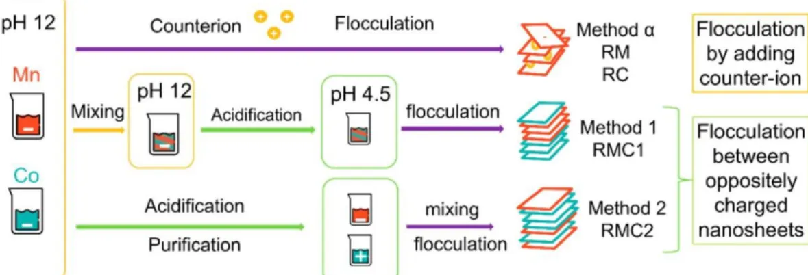
To control their restacking, a study of the surface charge of suspended nanosheets(66) is necessary to better understand the exfoliated particles. Indeed, the surface charge is the driving force for a controlled assembly. Depending on the pH and the oxidation state of metallic ions constitutive of the layers, the surface charge of the layers of interest can be clearly known through zeta potential measurements, and pH domains have been identified in which the objects are negatively or positively charged (as shown in Figure S1 in the Supporting Information). As a result, various restacking methods based on electrostatic interactions between the “building nanoblocks” were determined, as summarized in Figure 1.
Figure 1. Schematic representation of restacking methods. Method α consists in the destabilization of the initial solutions by addition of a counterion. This method is used for the restacking of monoelement layered materials (“RM” for restacked manganese oxide and “RC” for restacked cobalt oxide). Method 1 consists of mixing the suspensions at high pH = 12 then lowering it down, yielding the RMC1 material (restacked manganese–cobalt material). Method 2 consists of lowering the pH of each suspension before mixing it, yielding the RMC2 material.
The interest of the exfoliation/restacking strategy toward electrochemical properties is first validated by studying the restacking of monoelement (Mn or Co) “building blocks”. Only then do we proceed to the preparation of mixed Mn–Co restacked materials. For this, various restacking methods that rely on different interactions between the Mn and Co “building blocks” are used. As a result, the distinct restacked materials present different morphologies and physical chemical properties but always lead to improved electrochemical performances compared to initial materials. In addition, we discuss the influence of the restacking technique and the impact of morphology on the electrochemical performances. To our knowledge, it is the first time that such an extensive
study on the electrochemical performances of composite materials obtained by exfoliation/restacking of different layered materials has been conducted.
Method α
First, in order to study the effect of the exfoliation/restacking process on the materials properties, the colloidal suspensions of cobalt or manganese-based objects are restacked separately using method α. At the high pH of Mn and Co-based colloidal suspensions after exfoliation (without further treatment) (pH = 12), the surface charge of the Mn and Co-based particles is negative (see Figure S1 in the Supporting Information). Therefore, the most direct restacking technique is to induce flocculation of the negatively charged nanosheets by increasing the ionic strength of the solution, thus lowering the screening effect between slabs. This flocculation does not affect the 2D morphology of the nanosheets and usually produces a randomly restacked lamellar aggregate. It is performed by adding dropwise a solution of 1 M NaCl into the stable suspension until visible aggregation. RM (respectively RC) corresponds to the material obtained after exfoliation/restacking of H-MnO2 (respectively β3-CoOOH).
Methods 1 and 2
Mixed manganese–cobalt materials are obtained by inducing flocculation between oppositely charged nanosheets. Actually, initial suspensions are both negatively charged. However, by shifting the pH to 4.5, Co-based
nanosheets become positively charged and can attract negative Mn-based nanosheets. Two different strategies to change the pH can be adopted, leading to the RMC1 and RMC2 restacked Mn–Co materials. A schematic
summary of the restacking methods is presented in Figure 1 (methods 1 and 2). First, method 1 consists of mixing both initial colloidal suspensions (i.e., at the exfoliation pH of 12), leading to a mixed stable colloidal suspension. Then, in order to induce flocculation, the pH is decreased from 12 to the optimum pH of 4.5 by addition of nitric acid. A visual flocculation is observed, and the deposit is centrifuged and dried to obtain RMC1 (method 1). The second restacking method consists of bringing the Mn and Co-based colloidal suspensions to the optimum pH 4.5 separately, before mixing them together in a third vessel while carefully controlling the pH. This leads to RMC2 (method 2). The main difficulty of this last strategy is to stabilize the initial suspensions at pH 4.5 before mixing. Indeed, as the pH is lowered, ionic strength increases, leading to destabilization of the suspensions that aggregate. To counter this effect, purification is necessary with multiple cycles of centrifugation and resuspension by
ultrasonication prior to the restacking in order to get a finer restacking. At the end of these exfoliation/restacking processes, the mixed layered metal oxides obtained are analyzed. As a reference sample, mixed layered metal oxides are also prepared by simple thorough grinding, in a mortar, of initial H-MnO2 and β3-CoOOH pristine powders (before exfoliation). The obtained sample is denoted as MG (mechanically ground). For comparison sake, the Mn:Co ratio is fixed to 1:1 for all the mixed restacked materials, allowing an in-depth study of the influence of the restacking technique.
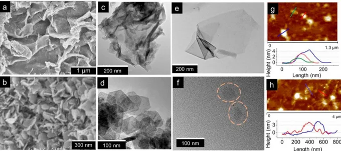
Before further discussion about the restacking, the successful exfoliation into building nanoblocks has been verified with various microscopy techniques. SEM and TEM images of the pristine birnessite and cobalt
oxyhydroxide are presented in Figure 2a–d. A clear difference in morphology and size between pristine H-MnO2 and β3-CoOOH can be observed. Indeed, H-MnO2 particles are wrinkled, veil-like lamellar objects. Particles do not appear as single objects but are rather aggregated which renders their size difficult to determine.
Nevertheless, the objects are estimated to be hundreds of nanometer wide. Whereas β3-CoOOH particles exist as flat hexagonal platelets with clear distinct edges. They are very well-defined; the platelets are around 60 nm wide and 10 nm thick.
The effect of the exfoliation process on the object morphology is presented in Figure 2e,f. Exfoliated H-MnO2 appears as micrometric sheets constituted by few layers, with a folding of the edges that reveals substantial exfoliation. The faint but uniform contrast reveals their ultrathin nature. In the case of cobalt based materials, the TEM image in Figure 2f shows platelet shapes of approximately 60–70 nm in good accordance with the
morphology observed for the starting phase before exfoliation. Tapping mode AFM was used to precisely measure the thickness of exfoliated objects, in order to estimate the number of oxide layers along the z-axis. The images and height profiles presented in Figure 2g,h correspond to nanosheets collected after purification of the exfoliated colloidal suspensions.
Celine Tang, Domitille Giaume, François Weill, Nicolas Penin, Marie Anne Dourges, et al.. Synergy of Mn and Co in slab-based nanocomposites for hybrid supercapacitors: impact of
Figure 2. SEM images of (a) pristine birnessite H-MnO2 and (b) pristine β3-CoOOH. TEM images of (c) pristine birnessite
H-MnO2 and (d) pristine β3-CoOOH. Exfoliated nanosheets of (e) H-MnO2 and (f) β3-CoOOH. Tapping-mode AFM images
and height profiles obtained in the last supernatant (50000 rpm) of exfoliated colloidal suspensions of (g) H-MnO2 nanosheets
and (h) β3-CoOOH nanosheets.
Exfoliated H-MnO2 sheets with a minimum thickness of 1.5 nm can be detected. According to crystallographic data, the theoretical thickness of one layer is 0.38 nm. However, the presence of water molecules between the nanosheets induces a discrepancy between the theoretical thickness and the experimentally obtained value. It can be therefore assumed that the height profile measured corresponds to two or three layers of manganese oxide. In the case of β3-CoOOH exfoliated particles, height profiles reveal the presence of 4 nm thick particles. From the crystal structure, the thickness of a CoO2 monolayer is 0.48 nm, thus revealing that, considering the hydration of nanosheets, six to eight sheets compose the nanoobjects after exfoliation.
X-ray Diffraction Study
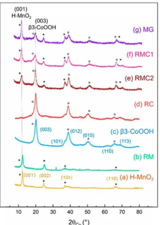
The X-ray diffraction patterns of the various materials synthesized and of and their parents (respectively H-MnO2 and β3-CoOOH) are shown in Figure 3. As far as the pure manganese (RM) or cobalt (RC) restacked materials are concerned, their diagrams (b and d) can be compared to those of their parent materials (a and c). The line
indexation reported for the manganese materials (H-MnO2 and RM) corresponds to a hexagonal cell (space group
P3̅m1, one slab per cell). For the cobalt-based materials (β3-CoOOH and RC), the indexation is performed with
three slabs per hexagonal cell (space group R3̅m). The sizes of the coherent domains, determined by the Scherrer method, on the basis of the (00 ) lines and (110) lines, are gathered in Table S1 (in the Supporting Information). Let us remember that the sizes associated with (00 ) (respectively 110) lines correspond to the thickness
(respectively width) of the coherent domains in a platelet morphology. Although RM and H-MnO2 both present patterns characteristic of birnessite phases, the lines are significantly broadened in the restacked sample,
suggesting a significant decrease of the size of coherent domains in the (001) and (110) directions. This is also verified by the broadening of the (10 ) lines observed in the final restacked material, characteristic of
turbostraticity. In addition, the inter-reticular distance of the (001) line corresponding to the interslab distance is slightly decreased for RM as compared with H-MnO2, indicating the successful intercalation of Na+ ions between the Mn-based layers. In comparison, the diffraction patterns of RC and its precursor β3-CoOOH are similar (Figure 3c,d), with no significant change in the size of coherent domains. This behavior suggests that the structure and crystallinity of cobalt-based materials are maintained by the exfoliation/restacking process. Flatness and rigidity of the β3-CoOOH layers revealed on Figure 2 could allow an easier restacking as compared to veil-like H-MnO2 nanosheets.
Figure 3. X-ray diffraction patterns of (a) pristine H-MnO2, (b) restacked manganese oxide (RM), (c) pristine β3-CoOOH, (d) restacked cobalt oxide (RC), (e) mixed material obtained by exfoliation/restacking with method 2 (RMC2), (f) mixed material obtained by exfoliation/restacking with method 1 (RMC1), and (g) reference material obtained by mechanical grinding of pristine materials (MG). The lines that correspond to H-MnO2 (β3-CoOOH respectively) are marked with (*) ((deg) respectively).
Mixed Mn–Co restacked materials RMC1 and RMC2 as well as the material prepared by mechanical grinding MG exhibit strong similarities in their X-ray diffraction patterns (Figure 3e–g). The Mn:Co ratios have been verified by chemical analysis, and all present a 1:1 ratio. The three diffractograms present lines characteristic of a mixture of the initial two phases: H-MnO2 and β3-CoOOH. This suggests a successful recombination of initial manganese and cobalt “building blocks” through exfoliation and various restacking processes. However, depending on the restacking method, the width and intensity of the (001) line of birnessite and of the (003) line of the cobalt oxyhydroxide phase vary, revealing different nanostructures. The intensity ratio between the (001) line of birnessite and the (003) line of the cobalt phase is in favor of birnessite for RMC1 obtained by fast acidification of the mixed colloidal suspensions. On the contrary, when the acidification is performed before mixing (RMC2), the intensity ratio is in favor of the cobalt phase.
The average crystallite sizes along the (00 ) directions (thickness of platelet-like objects), determined by the Scherrer formula, for manganese oxide and cobalt oxyhydroxide are gathered in Table S2 in the Supporting Information. The thickness of the manganese-based domains seems to be quite constant (around 6–7 nm)
whatever the restacking method, while the thickness of the cobalt-based domains is higher for RMC2 (6 nm) than for RMC1 (3 nm), suggesting that restacking kinetics plays a key role on the nanostructure of the final composite.
Scanning and Transmission Electron Microscopy Study
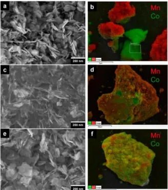
The organization at the mesoscopic scale of the mixed materials has been probed by SEM-EDS and TEM-EDS (energy-dispersive X-ray spectroscopy). The SEM images (presented in Figure 4) show that, in spite of the same Mn:Co ratio (determined by ICP analysis), the topographies of the mixed materials are very different.
Celine Tang, Domitille Giaume, François Weill, Nicolas Penin, Marie Anne Dourges, et al.. Synergy of Mn and Co in slab-based nanocomposites for hybrid supercapacitors: impact of
Figure 4. (a and b) SEM-EDS images of MG composite obtained by mechanical grinding of H-MnO2 and β3-CoOOH. (c and d) SEM-EDS images of RMC1 (restacking according to method 1). (e and f) SEM-EDS images of RMC2 (restacking according to method 2). Red and green colors correspond to manganese-rich and cobalt-rich, respectively, areas.
The H-MnO2 oxide particles are hardly distinguishable because of their veil-like morphologies, when the hexagonal platelets of β3-CoOOH can be easily observed. Moreover, these hexagonal platelets appear slightly more aggregated in the RMC2 sample. The EDS images of each sample also reveal significant differences. Images of the simply ground material MG show a clear segregation between the cobalt oxyhydroxide particles appearing in green and the manganese oxide particles in red, while on the images of the exfoliated/restacked materials RMC1 and RMC2, the Mn and Co elements appear to be intimately mixed, allowing the restacked compounds to be considered as nanocomposites of manganese oxide and cobalt oxyhydroxide. A closer observation of the EDS images of RMC1 and RMC2 leads to the conclusion that the restacking method clearly affects the homogeneity of the manganese and cobalt mixture. RMC2 seems to be the most homogeneous, as revealed by the appearance of a homogeneous yellow color, whereas RMC1 shows more manganese on the surface, the red color being
predominant. According to the TEM-EDS images, shown in Figure S2 (in the Supporting Information), it can also be observed that the MG sample shows a clear separation between cobalt oxyhydroxide and manganese oxide phases, whereas RMC1 and RMC2 both present intimately mixed Mn and Co elements. At this scale, it seems like RMC1 is more homogeneous than RMC2, as suggested by the presence of yellow color. However, this is not incoherent with the SEM results, as TEM probes the entire volume of the sample, instead of only the surface. The particle observed in Figure S2b is most likely thicker than the particle observed in Figure S2c.
Although all three mixed materials have the same Mn:Co ratio, their morphologies exhibit differences. This can be reasonably attributed to the restacking technique: the flocculation kinetics are different for Co oxyhydroxides and Mn oxides, depending on the restacking and the pH modification process used. Indeed, throughout exfoliation, it has been observed that the cobalt oxyhydroxide suspensions are less stable than the manganese oxide
suspensions. When pH is decreased close to the isoelectric point (IEP) of the exfoliated materials, the nanosheets are greatly destabilized and are more inclined to restack one onto another. By rapidly adding the mixed Mn–Co colloidal suspension to a strong acid solution at pH 1, close to the (IEP) of manganese objects, restacking method 1 favors the flocculation of Mn oxides. In the restacking method 2, each colloidal suspension is acidified to pH 4.5 before being mixed together. At this pH, both materials bear a lower surface charge than at high pH, allowing a slight restacking of Co oxyhydroxides. This consequently leads to bigger Co oxyhydroxide crystallites than in method 1, where Co oxyhydroxides are destabilized in the presence of Mn oxide particles and thus restack upon them. The bigger size of cobalt oxyhydroxide crystallites obtained by method 2 is in good agreement with the fact that the size of the coherent domains deduced from the Scherrer method is significantly higher for method 2 (6 nm) than for method 1 (3 nm), as reported in Supporting Information Table S2. This size difference is reflected in the X-ray diagrams (Figure3e,f) by the fact that the line (003) of CoOOH is thinner and more intense in RMC2 than in RMC1. Restacking method 2 is suitable to obtain Mn-rich and Co-rich aggregates with a similar size, giving rise to the most homogeneous sample.
Specific Surface Measurements
As stated before, the electrochemical properties of electrode materials greatly depend on their specific surface area and electronic conductivity. The specific surface area of restacked materials RC, RM, RMC1, and RMC2, obtained by BET measurements, are tabulated in Table 1.
From the N2 adsorption/desorption isotherms (Figure S3 of the Supporting Information), it seems that simple restacked materials RM and RC exhibit lower specific surface area than their parent materials. Intuitively, it is expected that the surface area should increase after exfoliation. A possible explanation for this decrease is the restacking strategy employed. The restacking process is very random: instead of being well ordered, the
nanosheets will tend to restack in arbitrary directions in a more packed manner, which could lead to a decrease of surface area. The isotherms of the mixed restacked RMC1 and RMC2 materials and of reference mechanically mixed MG exhibit a similar shape, as pristine materials. The calculated specific surfaces of RMC1, RMC2, and MG are also very close (between 90 to 100 m2/g) and intermediate between pristine manganese oxide (85 m2/g) and cobalt oxyhydroxide (110 m2/g). At first sight, it appears surprising that the exfoliation/restacking process results in surface area decrease only for RM or RC and not for RMC. As a matter of fact, the restacking processes used for RM (or RC) and RMC are different. The negatively charged nanosheets of RM and RC are restacked by
flocculation on Na+ cations provided by simple addition of NaCl in the pristine stable colloidal suspensions, whereas RMC is formed by attraction of positive Co-based nanosheets and negative Mn-based nanosheets at pH 4.5, without any salt addition. It can be supposed that, for RM and RC, the flocculation of identical Mn or Co slabs on Na+ cations is likely to be performed in a more packed manner, while in RMC samples, two different types of sheets are restacked, which probably does not favor such a packed sample.
Electronic Conductivity Measurements
The electronic conductivity measurement results of RMC2 (most homogeneous mixed restacked sample) and MG (mechanical ground mixture) are presented and compared to the pristine materials in Figure 5. H-MnO2 presents a low electronic conductivity that is activated by temperature. At room temperature, the conductivity value is equal to 7.2 × 10⁻⁵ S/cm, while β3-CoOOH exhibits a good conductivity of 1.8 S/cm, which is 5 orders of magnitude higher. For a composite made of 50% H-MnO2 and 50% β3-CoOOH, in which β3-CoOOH particles should percolate, an intermediate conductivity would be expected. Nevertheless, in the case of a simple
mechanical grinding (1.4 × 10⁻⁵ S/cm) as well as of restacking (6.7 × 10⁻⁵ S/cm), the conductivities of the samples are on the same order of magnitude as H-MnO2 (7.2 × 10⁻⁵ S/cm). We do not observe the expected increase of electronic conductivity due to the presence of β3-CoOOH at the sample scale. Nevertheless, as it will be reported in a forthcoming paper specifically devoted to electronic properties, BDS (broadband dielectric spectroscopy) measurements carried out on our materials help explain this observation. The results lead to the conclusion that the global conductivity of the Mn–Co composite is not enhanced because there is no electronic percolation between the Co nano-objects, in spite of a geometrical percolation. This can be attributed to an electron trapping phenomenon occurring at particle junctions.(67,68) The most probable hypothesis is that the electrons are blocked on the grain boundaries by the various protons present in the structure. Their poor conductivity could have a
Celine Tang, Domitille Giaume, François Weill, Nicolas Penin, Marie Anne Dourges, et al.. Synergy of Mn and Co in slab-based nanocomposites for hybrid supercapacitors: impact of
detrimental impact on the electrochemical properties of the restacked materials, especially on RMC2, the most homogeneously restacked material.
Figure 5. (a) Thermal variation of electronic conductivity for the restacked material RMC2 and the MG
sample obtained by mechanical grinding of H-MnO2 and β3-CoOOH (ratio 50% Mn and 50% Co).
These are compared to the as-prepared pristine materials. (b) Table presenting activation energy and
conductivity at room temperature of the materials.
Electrochemical Properties
The electrochemical properties of the materials are illustrated by the curves in Figure 6. Impact of exfoliation on electrochemical properties was first evaluated by comparing the electrochemical behaviors of
exfoliated/flocculated manganese oxide (RM) and cobalt oxyhydroxide (RC) to their pristine parents H-MnO2 and β3-CoOOH. The variations of specific capacitances vs scan rate are presented in Figure 6a for the four materials.
Pristine β3-CoOOH reveals a very low capacitance while pristine H-MnO2 exhibits a high pseudocapacitance, as already reported.(69,70) In both cases, the specific capacitances obtained for exfoliated/restacked materials are systematically higher than their initial parents. This trend can be attributed to a different structuration of
nanosheets induced by exfoliation, resulting in an increase of the active electrochemical surface in contact with the electrolyte. However, as shown previously, the specific surface areas are significantly lower for the
exfoliated/restacked materials than for the initial materials. This is contrary to what is expected in relation with the enhanced specific capacitances. It is possible to interpret this by claiming the discrepancy between specific surface area measured by BET and the electrochemically active surface that contributes to charge storage. In other terms, for RM or RC, the number of electrochemically active sites might increase due to the exfoliation effect, whereas the surface accessible by gas decreases (measured by BET) due to special reorganization of the nanosheets during flocculation on Na+ cations.
Figure 6. (a) Capacitance (normalized to the mass of active material) vs scan rate obtained for initial
materials and corresponding exfoliated/restacked derived materials prepared by flocculation (method α).
Cyclic voltammograms of initial β3-CoOOH, H-MnO
2, compared to mechanically ground mixture MG,
and restacked materials RMC1 and RMC2 in a three-cell configuration, with Ag/AgCl as reference
electrode and Pt as counter electrode, in 0.5 M K
2SO
4electrolyte at scan rates of (b) 5 mV/s and (c) 50
mV/s. (d) Capacitance vs scan rate obtained for all the materials.
After proving that simple exfoliation efficiently improves the electrochemical performances as compared to pristine initial materials, it is interesting to test restacked mixed manganese–cobalt materials (RMC1, RMC2) as supercapacitor electrodes, in comparison with the simple mechanical mixture of the pristine materials (MG). The cyclic voltammograms are presented in Figure 6b,c, and the variations of the corresponding specific capacitances are displayed in Figure 6d. At a scan rate of 5 mV/s, the voltammograms of all three composite samples exhibit more rectangular shapes than initial birnessite, which means that they present lower internal resistance than the initial materials. Moreover, since these materials contain only 50% of birnessite as active material, it can be
concluded that the enhanced diffusion pathways allow a better use of birnessite pseudocapacitance. Nevertheless, at a low rate (lower than 10 mV/s), the specific capacitances of the three composites are lower than for pristine birnessite. It is at high regime, when the scan rate is increased to 50 mV/s, that the beneficial effect of adding cobalt oxyhydroxide to the manganese oxide active material is the most obvious. Even with the presence of only 50% of birnessite, capacitances of all mixed materials are higher than the H-MnO2 initial birnessite. Moreover, RMC2 is revealed to be more performant than RMC1 and has been proved below to be more homogeneous than RMC1, thus indicating the impact of the restacking method on the performances of the obtained materials. Such a mixture at the nanometer scale favors charge carrier transport in the materials, even if no significant increase of the electronic conductivity measured by the four probe method can be detected. To sum up, restacking method 2 consisting of first adjusting the pH of separate colloidal suspensions of Mn and Co-based nanosheets before mixing them together enables a finer, more homogeneous flocculation leading to the most performant material of the series.
In the context of an application in supercapacitors, the cyclability of the electrodes is very important. RMC2 was then cycled up to 10000 cycles (cyclic voltammetry at 10 mV/s) and compared to its mechanically ground
homologous material (MG). The capacitance variations vs cycle number are shown in the Supporting Information (Figure S4). First of all, the restacked material shows higher specific capacitance than the simply mixed one, even at the very beginning of the cycling. Second, its capacitance is constant with a high capacitance retention up to
Celine Tang, Domitille Giaume, François Weill, Nicolas Penin, Marie Anne Dourges, et al.. Synergy of Mn and Co in slab-based nanocomposites for hybrid supercapacitors: impact of
10000 cycles, whereas the MG mechanically mixed material shows a non-negligible decrease of capacitance after 3000 cycles. The bad cyclability of the simply mixed composite can be attributed to a progressive loss of cohesion between the manganese oxide and carbon particles during cycling, leading to higher intergranular resistances, whereas the interfaces between the manganese and cobalt particles might be more robust in the restacked sample.
Conclusion
The results presented here illustrate the success of the exfoliation/restacking strategy of 2D layered materials in designing mixed nanocomposites with enhanced electrochemical performances. Starting from the 2D layered birnessite, which presents excellent pseudocapacitive properties but low conductivity, we address this issue with the help of cobalt oxyhydroxide, known for its high electronic conductivity. In order to preserve the properties of each initial material while creating a synergistic effect, the synthesis involves delamination into “building nanoblocks” which are then restacked in order to obtain a novel nanocomposite material. Two restacking processes were conducted, and in both cases, the obtained mixed compounds are identified as Mn–Co
nanocomposites showing a more intimate mixture at the nanometric scale than by mechanical grinding of pristine materials. As far as the electrochemical properties are concerned, a synergistic effect between Mn oxides and Co oxyhydroxides is achieved, and a clear impact of the restacking method on the morphology and on the
electrochemical activity is observed. Deeper influence of the Mn:Co ratio in such nanocomposites is presently investigated and will be the object of a forthcoming paper.
Methods
Preparation of Initial 2D Nanomaterials
Layered potassium manganese oxide powder was prepared at room temperature by precipitation of a manganese salt in an alkaline oxidant solution. A total of 10.0 mmol of Mn(SO4)·H2O (Sigma-Aldrich) was dissolved in 30 mL of water in a plastic beaker, and a solution of KOH (Sigma-Aldrich, 6 M, 30 mL) was added rapidly, leading to a brown solution. The vigorous stirring was maintained while the 7.0 mmol of K2S2O8 (Sigma-Aldrich) was added very slowly over a period of over 45 min. The resulting brown-black slurry was stirred for an additional 30 min before being washed with distilled water and finally dried at 60 °C for 24 h. To facilitate exfoliation, the resulting powder was treated with 0.1 M HCl solution for 4 days at room temperature to produce the proton-inserted birnessite manganese oxide (H-MnO2). The exfoliated layered manganese oxide nanosheets were synthesized by reaction of the protonated manganese birnessite with tetrabutylammonium hydroxide (Sigma-Aldrich) for 12 days at room temperature. The amount of TBAOH applied with respect to the exchangeable protons (TBA+/H+) was fixed to 10 after optimization. The resulting colloidal suspension was centrifuged at a speed of 6000 rpm for 15 min to remove the fraction of incompletely exfoliated particles.
β(III)-type layered cobalt oxyhydroxide was synthesized by precipitation at room temperature of a cobalt salt in alkaline oxidant media. Co(NO3)2 (Sigma-Aldrich) was dissolved in 300 mL of distilled water and added dropwise in 11 mL of 2 M NaOH (Sigma-Aldrich). Then, a solution of 4.8 M - NaClO was added as a strong oxidant. The mixture was stirred for 5–30 min and centrifugated 8 times (6000 rpm for 4 min) until the
supernatant reached neutrality. The powder was recovered after having dried at 60 °C for 24 h. The powder was suspended in an aqueous solution of TBAOH for 20 days at room temperature under vigorous stirring. The amount of TBAOH applied with respect to the exchangeable protons (TBA+/H+) was fixed to 2 after optimization. Then the colloidal suspension obtained was centrifuged at 6000 rpm for 15 min to remove the fraction of incompletely exfoliated particles.
Material Characterization
X-ray Diffraction
The X-ray powder diffraction analyses were carried out on a Philips Panalytical X’Pert Pro diffractometer with a Bragg–Brentano θ–θ geometry. In the case of manganese oxides, a copper Kα radiation was used (λKα2= 1.54439 Å, λKα1= 1.54056 Å). The powder diffraction patterns were recorded for about 2 h in the 8°–80° (2θ) angular range, with a 0.0167° (2θ) step size and a 2.122° (2θ) active width in the detector. In the case of cobalt oxyhydroxides, a cobalt Kα radiation (λKα2= 1.7928 Å, λKα1= 1.7889 Å) was used. The powder diffraction patterns were recorded for about 10 h in the 10°–110° (2θ) angular range, with a 0.0167° (2θ) step size and a 2.122° (2θ) active width in the detector.
ICP-OES Spectroscopy Measurements
Co, Mn, K, and Na elements were quantified in our samples using a Varian 720ES ICP-OES spectrometer. Powdered samples (10–20 mg) were dissolved into boiling HCl, and the obtained solutions were diluted in order to obtain concentrations varying from 1 to 200 mg/L. Solutions were then introduced in a nebulization chamber along with an argon flow to create an aerosol.
Transmission Electron Microscopy
Transmission electron microscopy (TEM) of 2D materials deposited on a carbon-coated copper grid was done with a JEOL 2200FS microscope equipped with a high-resolution camera. The microscope was used at 200 kV. In this case, the resolution is 0.19 nm. A JEOL JSM 7800F Prime scanning electron microscope (SEM) equipped with an EDS system was used to characterize the microstructure of the layered materials. The acceleration voltage used was from 1 to 30 kV.
Atomic Force Microscopy
Atomic force microscopy images were recorded by the tapping-mode phase imaging using a standard silicon cantilever (approx 20 N/m, 150 kHz) on a commercial ICON AFM (Bruker). The software used to analyze the images is Nanoscope Analysis. For the analysis, it is particularly critical to avoid reaggregation of nanosheets on the wafer during solvent evaporation. For this, very dilute dispersions are used and drop-casted onto a
microscope slide. The slide is pretreated with a freshly cleaved mica surface in order to obtain an atomically flat surface. The zeta potentials of the dispersions were measured with a Malvern Zetasizer Nano series. The Zetasizer Nano series calculates the zeta potential by determining the electrophoretic mobility and then applying the Henry equation. The electrophoretic mobility is obtained by performing an electrophoresis experiment on the sample and measuring the velocity of the particles using laser doppler velocimetry (LDV).
Purification of the Exfoliated Colloidal Suspensions for AFM Measurements on Nanosheets
In order to characterize the produced nanosheets after exfoliation, they must be separated from the bulk unexfoliated material, and size-selection is required. To do so, liquid cascade centrifugation is used, which consists of a multistep process where various centrifugations at increasing speeds (4000, 20000, and 50000 rpm) are carried out. The first centrifugation at 4000 rpm allows the nonexfoliated material to be recovered in the bottom of the flask. After each subsequent step, size-selected nanosheets are collected as sediments while the supernatant is subjected to another centrifugation at higher rotation speed.
N
2Adsorption Measurements
All the specific surface measurements and characterization of material mesoporosity were conducted by N2 adsorption at 77 K. The measurements were performed on ASAP2010 (Micromeritics Corp., Norcross, GA, U.S.A.). Each sample was degassed at 100 °C under vacuum during the necessary time to obtain a constant pressure of 10 μm Hg (approximately 12–15 h). The BET model was applied for relative pressures (P/P0) between 0.01 and 0.3 to calculate the specific surface SBET. Pore distribution was determined using the BJH model. The pore dimensions were calculated from the desorption isotherms.
Electric Conductivity Measurements
The electric conductivity measurements have been performed with the four-probe technique, using direct current in the 230–400 K temperature range. Because of their instability beyond 400 K, the materials could not be sintered and the measurements were performed on pellets (8 mm in diameter) obtained by compacting 200 mg of powder at 1.2 GPa.
Electrochemical Cycling
All electrochemical performances were evaluated in a three-electrode cell filled with an 0.5 M K2SO4 electrolyte. Platinum was used as counter electrode and Ag/AgCl as reference electrode. The working electrode was prepared by mixing 80% active material powder, 5% PTFE (Sigma-Aldrich, 60 wt % water suspension), and 15% of carbon black (conductive additive made of acetylene, 100% compressed, Alfa Aesar) with ethanol. The mixture was set as an autosupported film, in which an 8 mm diameter disc was cut and pressed on a stainless steel grid as current collector at 6 t/cm2 for 5 min. Electrochemical cyclic voltammetry was completed using a VMP3
potentiostat (Biologic) under ECLab software and was performed at 5 and 50 mV/s between 0 and 0.8 V.
Acknowledgements
This work was supported by RS2E through Celine Tang’s grant (LABEX STORE-EX ANR-10-LABX-01). The authors would like to deeply thank Philippe Legros et Marion Gayot from PLACAMAT (UMS 3626 CNRS-UB) for the SEM-EDS and TEM-EDS cartography, respectively. A special notice to Gregory Lefèvre for his help in
understanding the interactions between oxides in solution, as well as P. Dagault, C. Denage, and S. Goma for their technical support.
Celine Tang, Domitille Giaume, François Weill, Nicolas Penin, Marie Anne Dourges, et al.. Synergy of Mn and Co in slab-based nanocomposites for hybrid supercapacitors: impact of
Supporting informations
The Supporting Information is available free of charge on the ACS Publications website at DOI:
10.1021/acsaem.9b01263.
Experimental zeta potential–pH curves of initial protonated birnessite H-MnO2 particles (red) and β3-CoOOH cobalt oxyhydroxide, average sizes (nm) of coherent domains along (00 ) and (110) directions determined by Scherrer method for pristine and restacked materials, TEM-EDS images of the materials, N2
adsorption/desorption isotherms at 77 K of the pristine and restacked materials, and cyclability of restacked material RMC2 vs mechanically mixed composite (PDF).
References
1 Kousksou, T.; Bruel, P.; Jamil, A.; El Rhafiki, T.; Zeraouli, Y. Energy Storage: Applications and Challenges. Sol. Energy Mater. Sol. Cells 2014,
120, 59– 80, DOI: 10.1016/j.solmat.2013.08.015
2 Tarascon, J.-M.; Armand, M. Issues and Challenges Facing Rechargeable Lithium Batteries. Nature 2001, 414 (6861), 359– 367, DOI:
10.1038/35104644
3 Conway, B. E. Transition from “supercapacitor” to “Battery” Behavior in Electrochemical Energy Storage. J. Electrochem. Soc. 1991, 138
(6), 1539– 1548, DOI: 10.1149/1.2085829
4 Simon, P.; Gogotsi, Y.; Dunn, B. Where Do Batteries End and Supercapacitors Begin?. Science 2014, 343 (6176), 1210– 1211, DOI:
10.1126/science.1249625
5 Miller, J. R.; Simon, P. Electrochemical Capacitors for Energy Management. Science 2008, 321 (5889), 651– 652, DOI:
10.1126/science.1158736
6 Pandolfo, A. G.; Hollenkamp, A. F. Carbon Properties and Their Role in Supercapacitors. J. Power Sources 2006, 157 (1), 11– 27, DOI:
10.1016/j.jpowsour.2006.02.065
7 Lewandowski, A.; Olejniczak, A.; Galinski, M.; Stepniak, I. Performance of Carbon–Carbon Supercapacitors Based on Organic, Aqueous and
Ionic Liquid Electrolytes. J. Power Sources 2010, 195 (17), 5814– 5819, DOI: 10.1016/j.jpowsour.2010.03.082
8 Qu, D. Studies of the Activated Carbons Used in Double-Layer Supercapacitors. J. Power Sources 2002, 109 (2), 403– 411, DOI:
10.1016/S0378-7753(02)00108-8
9 Vivekchand, S. R. C.; Rout, C. S.; Subrahmanyam, K. S.; Govindaraj, A.; Rao, C. N. R. Graphene-Based Electrochemical Supercapacitors.
Proc. - Indian Acad. Sci., Chem. Sci. 2008, 120 (1), 9– 13, DOI: 10.1007/s12039-008-0002-7
10 Du, X.; Guo, P.; Song, H.; Chen, X. Graphene Nanosheets as Electrode Material for Electric Double-Layer Capacitors. Electrochim. Acta
2010, 55 (16), 4812– 4819, DOI: 10.1016/j.electacta.2010.03.047
11 Kaempgen, M.; Chan, C. K.; Ma, J.; Cui, Y.; Gruner, G. Printable Thin Film Supercapacitors Using Single-Walled Carbon Nanotubes. Nano
Lett. 2009, 9 (5), 1872– 1876, DOI: 10.1021/nl8038579
12 Yu, D.; Dai, L. Self-Assembled Graphene/Carbon Nanotube Hybrid Films for Supercapacitors. J. Phys. Chem. Lett. 2010, 1 (2), 467– 470,
DOI: 10.1021/jz9003137
13 Conway, B. E.; Birss, V.; Wojtowicz, J. The Role and Utilization of Pseudocapacitance for Energy Storage by Supercapacitors. J. Power
Sources 1997, 66 (1–2), 1– 14, DOI: 10.1016/S0378-7753(96)02474-3
14 Zheng, J. P.; Cygan, P. J.; Jow, T. R. Hydrous Ruthenium Oxide as an Electrode Material for Electrochemical Capacitors. J. Electrochem.
Soc. 1995, 142 (8), 2699– 2703, DOI: 10.1149/1.2050077
15 De Pauli, C. P.; Trasatti, S. Electrochemical Surface Characterization of IrO2 + SnO2Mixed Oxide Electrocatalysts. J. Electroanal. Chem.
1995, 396, 161– 168, DOI: 10.1016/0022-0728(95)03950-L
16 Liu, K.-C.; Anderson, M. A. Porous Nickel Oxide/Nickel Films for Electrochemical Capacitors. J. Electrochem. Soc. 1996, 143 (1), 124– 130,
DOI: 10.1149/1.1836396
17 Zhang, Y.; Hu, Z.; An, Y.; Guo, B.; An, N.; Liang, Y.; Wu, H. High-Performance Symmetric Supercapacitor based on Manganese
Oxyhydroxide Nanosheets on Carbon Cloth as Binder-Free Electrodes. J. Power Sources 2016, 311, 121– 129, DOI: 10.1016/j.jpowsour.2016.02.017
18 Lee, H. Y.; Goodenough, J. B. Supercapacitor Behavior with KCl Electrolyte. J. Solid State Chem. 1999, 144 (1), 220– 223, DOI:
10.1006/jssc.1998.8128
19 Toupin, M.; Brousse, T.; Bélanger, D. Charge Storage Mechanism of MnO2 Electrode Used in Aqueous Electrochemical Capacitor. Chem.
Mater. 2004, 16 (16), 3184– 3190, DOI: 10.1021/cm049649j
20 Holze, R.; Wu, Y. P. Intrinsically Conducting Polymers in Electrochemical Energy Technology: Trends and Progress. Electrochim. Acta
2014, 122, 93– 107, DOI: 10.1016/j.electacta.2013.08.100
21 Rudge, A.; Raistrick, I.; Gottesfeld, S.; Ferraris, J. P. A Study of the Electrochemical Properties of Conducting Polymers for Application in
Electrochemical Capacitors. Electrochim. Acta 1994, 39 (2), 273– 287, DOI: 10.1016/0013-4686(94)80063-4
22 Laforgue, A.; Simon, P.; Sarrazin, C.; Fauvarque, J.-F. Polythiophene-Based Supercapacitors. J. Power Sources 1999, 80 (1), 142– 148, DOI:
10.1016/S0378-7753(98)00258-4
23 Rudge, A.; Davey, J.; Raistrick, I.; Gottesfeld, S.; Ferraris, J. P. Conducting Polymers as Active Materials in Electrochemical Capacitors. J.
Power Sources 1994, 47 (1–2), 89– 107, DOI: 10.1016/0378-7753(94)80053-7
24 Huang, Z.-H.; Song, Y.; Xu, X.-X.; Liu, X.-X. Ordered Polypyrrole Nanowire Arrays Grown on a Carbon Cloth Substrate for a
High-Performance Pseudocapacitor Electrode. ACS Appl. Mater. Interfaces 2015, 7 (45), 25506– 25513, DOI: 10.1021/acsami.5b08830
25 Vernitskaya, T. V.; Efimov, O. N. Polypyrrole: A Conducting Polymer; Its Synthesis, Properties and Applications. Russ. Chem. Rev. 1997, 66
26 Huang, M.; Li, F.; Dong, F.; Zhang, Y. X.; Zhang, L. L. MnO2-based Nanostructures for High-Performance Supercapacitors. J. Mater. Chem.
A 2015, 3, 21380– 21423, DOI: 10.1039/C5TA05523G
27 Hu, C.-C.; Tsou, T.-W. Ideal Capacitive Behavior of Hydrous Manganese Oxide Prepared by Anodic Deposition. Electrochem. Commun.
2002, 4 (2), 105– 109, DOI: 10.1016/S1388-2481(01)00285-5
28 Brousse, T.; Toupin, M.; Dugas, R.; Athouël, L.; Crosnier, O.; Bélanger, D. Crystalline MnO2 as Possible Alternatives to Amorphous
Compounds in Electrochemical Supercapacitors. J. Electrochem. Soc. 2006, 153, A2171– A2180, DOI: 10.1149/1.2352197
29 Devaraj, S.; Munichandraiah, N. Effect of Crystallographic Structure of MnO2 on Its Electrochemical Capacitance Properties. J. Phys.
Chem. C 2008, 112 (11), 4406– 4417, DOI: 10.1021/jp7108785
30 Pang, S.-C.; Anderson, M. A.; Chapman, T. W. Novel Electrode Materials for Thin-Film Ultracapacitors: Comparison of Electrochemical
Properties of Sol-Gel-Derived and Electrodeposited Manganese Dioxide. J. Electrochem. Soc. 2000, 147 (2), 444– 450, DOI: 10.1149/1.1393216
31 Zhang, K.; Han, X.; Hu, Z.; Zhang, X.; Tao, Z.; Chen, J. Nanostructured Mn-based oxides for electrochemical energy storage and
conversion. Chem. Soc. Rev. 2015, 44, 699– 728, DOI: 10.1039/C4CS00218K
32 Wang, J.-G.; Kang, F.; Wei, B. Engineering of MnO2-Based Nanocomposites for High-Performance Supercapacitors. Prog. Mater. Sci.
2015, 74, 51– 124, DOI: 10.1016/j.pmatsci.2015.04.003
33 Luo, D.; Wallar, C. J.; Shi, K.; Zhitomirsky, I. Enhanced Capacitive Performance of MnO2- Multiwalled Carbon Nanotube Electrodes,
Prepared Using Lauryl Gallate Dispersant. Colloids Surf., A 2016, 509, 504– 511, DOI: 10.1016/j.colsurfa.2016.09.065
34 Higgins, T. M.; McAteer, D.; Coelho, J. C. M.; Sanchez, B. M.; Gholamvand, Z.; Moriarty, G.; McEvoy, N.; Berner, N. C.; Duesberg, G. S.;
Nicolosi, V.; Coleman, J. N. Effect of Percolation on the Capacitance of Supercapacitor Electrodes Prepared from Composites of Manganese Dioxide Nanoplatelets and Carbon Nanotubes. ACS Nano 2014, 8, 9567– 9579, DOI: 10.1021/nn5038543
35 Tang, X.; Liu, Z.; Zhang, C.; Yang, Z.; Wang, Z. Synthesis and Capacitive Property of Hierarchical Hollow Manganese Oxide Nanospheres
with Large Specific Surface Area. J. Power Sources 2009, 193 (2), 939– 943, DOI: 10.1016/j.jpowsour.2009.04.037
36 Wang, P.; Zhao, Y.-J.; Wen, L.-X.; Chen, J.-F.; Lei, Z.-G. Ultrasound–Microwave-Assisted Synthesis of MnO2 Supercapacitor Electrode
Materials. Ind. Eng. Chem. Res. 2014, 53 (52), 20116– 20123, DOI: 10.1021/ie5025485
37 Coleman, J. N.; Lotya, M.; O’Neill, A.; Bergin, S. D.; King, P. J.; Khan, U.; Young, K; Gaucher, A.; De, S.; Smith, R. J. Two-Dimensional
Nanosheets Produced by Liquid Exfoliation of Layered Materials. Science 2011, 331, 568– 571, DOI: 10.1126/science.1194975
38 Han, T. H.; Lee, W. J.; Lee, D. H.; Kim, J. E.; Choi, E. Y.; Kim, S. O. Peptide/Graphene Hybrid Assembly into Core/Shell Nanowires. Adv.
Mater. 2010, 22, 2060– 2064, DOI: 10.1002/adma.200903221
39 Luckham, P. F.; Rossi, S. The Colloidal and Rheological Properties of Bentonite Suspensions. Adv. Colloid Interface Sci. 1999, 82 (1–3), 43–
92, DOI: 10.1016/S0001-8686(99)00005-6
40 Tanaka, T.; Ebina, Y.; Takada, K.; Kurashima, K.; Sasaki, T. Oversized Titania Nanosheet Crystallites Derived from Flux-Grown Layered
Titanate Single Crystals. Chem. Mater. 2003, 15 (18), 3564– 3568, DOI: 10.1021/cm034307j
41 Eda, G.; Yamaguchi, H.; Voiry, D.; Fujita, T.; Chen, M.; Chhowalla, M. Photoluminescence from Chemically Exfoliated MoS2. Nano Lett.
2011, 11, 5111– 5116, DOI: 10.1021/nl201874w
42 Lotya, M.; Hernandez, Y.; King, P. J.; Smith, R. J.; Nicolosi, V.; Karlsson, L. S.; Blighe, F. M.; De, S.; Wang, Z.; McGovern, I. T.; Duesberg, G.
S.; Coleman, J. N. Liquid Phase Production of Graphene by Exfoliation of Graphite in Surfactant/Water Solutions. J. Am. Chem. Soc. 2009, 131, 3611– 3620, DOI: 10.1021/ja807449u
43 Liu, Z.; Ooi, K.; Kanoh, H.; Tang, W.; Tomida, T. Swelling and Delamination Behaviors of Birnessite-Type Manganese Oxide by
Intercalation of Tetraalkylammonium Ions. Langmuir 2000, 16 (9), 4154– 4164, DOI: 10.1021/la9913755
44 Omomo, Y.; Sasaki, T.; Wang; Watanabe, M. Redoxable Nanosheet Crystallites of MnO2 Derived via Delamination of a Layered
Manganese Oxide. J. Am. Chem. Soc. 2003, 125 (12), 3568– 3575, DOI: 10.1021/ja021364p
45 Ma, R.; Sasaki, T. Two-Dimensional Oxide and Hydroxide Nanosheets: Controllable High-Quality Exfoliation, Molecular Assembly, and
Exploration of Functionality. Acc. Chem. Res. 2015, 48 (1), 136– 143, DOI: 10.1021/ar500311w
46 Liu, J.; Essner, J.; Li, J. Hybrid Supercapacitor Based on Coaxially Coated Manganese Oxide on Vertically Aligned Carbon Nanofiber Arrays.
Chem. Mater. 2010, 22 (17), 5022– 5030, DOI: 10.1021/cm101591p
47 Huang, M.; Mi, R.; Liu, H.; Li, F.; Zhao, X. L.; Zhang, W.; He, S. X.; Zhang, Y. X. Layered Manganese Oxides-Decorated and Nickel
Foam-Supported Carbon Nanotubes as Advanced Binder-Free Supercapacitor Electrodes. J. Power Sources 2014, 269, 760– 767, DOI: 10.1016/j.jpowsour.2014.07.031
48 Kim, M.; Hwang, Y.; Kim, J. Super-Capacitive Performance Depending on Different Crystal Structures of MnO2 in Graphene/MnO2
Composites for Supercapacitors. J. Mater. Sci. 2013, 48 (21), 7652– 7663, DOI: 10.1007/s10853-013-7583-3
49 Chen, S.; Zhu, J.; Wu, X.; Han, Q.; Wang, X. Graphene Oxide-MnO2 Nanocomposites for Supercapacitors. ACS Nano 2010, 4 (5), 2822–
2830, DOI: 10.1021/nn901311t
50 Snook, G. A.; Kao, P.; Best, A. S. Conducting-Polymer-Based Supercapacitor Devices and Electrodes. J. Power Sources 2011, 196 (1), 1–
12, DOI: 10.1016/j.jpowsour.2010.06.084
51 Duay, J.; Gillette, E.; Liu, R.; Lee, S. B. Highly Flexible Pseudocapacitor Based on Freestanding Heterogeneous MnO 2/Conductive Polymer
Nanowire Arrays. Phys. Chem. Chem. Phys. 2012, 14 (10), 3329– 3337, DOI: 10.1039/c2cp00019a
52 Clark, M. P.; Qu, W.; Ivey, D. G. Nanostructured Manganese Oxide and Manganese Oxide/Polyethylenedioxythiophene Rods
Electrodeposited onto Nickel Foam for Supercapacitor Applications. J. Appl. Electrochem. 2017, 47, 39– 49, DOI: 10.1007/s10800-016-1015-4
53 Ni, W.; Wang, D.; Huang, Z.; Zhao, J.; Cui, G. Fabrication of Nanocomposite Electrode with MnO2 Nanoparticles Distributed in Polyaniline
for Electrochemical Capacitors. Mater. Chem. Phys. 2010, 124 (2–3), 1151– 1154, DOI: 10.1016/j.matchemphys.2010.08.050
54 Lang, X.; Hirata, A.; Fujita, T.; Chen, M. Nanoporous Metal/Oxide Hybrid Electrodes for Electrochemical Supercapacitors. Nat.
Nanotechnol. 2011, 6 (4), 232– 236, DOI: 10.1038/nnano.2011.13
55 Li, Y.; Fu, H.; Zhang, Y.; Wang, Z.; Li, X. Kirkendall Effect Induced One-Step Fabrication of Tubular Ag/MnOx Nanocomposites for
Celine Tang, Domitille Giaume, François Weill, Nicolas Penin, Marie Anne Dourges, et al.. Synergy of Mn and Co in slab-based nanocomposites for hybrid supercapacitors: impact of
56 Chen, J.; Huang, Y.; Li, C.; Chen, X.; Zhang, X. Synthesis of NiO@MnO2 Core/Shell Nanocomposites for Supercapacitor Application. Appl.
Surf. Sci. 2016, 360, 534– 539, DOI: 10.1016/j.apsusc.2015.10.187
57 Wang, Z.; Wang, F.; Tu, J.; Cao, D.; An, X.; Ye, Y. Nickel Foam Supported Hierarchical Mesoporous MnO2/Ni(OH)2 Nanosheet Networks
for High Performance Supercapacitor Electrode. Mater. Lett. 2016, 171, 10– 13, DOI: 10.1016/j.matlet.2016.02.050
58 Liu, E.-H.; Li, W.; Li, J.; Meng, X.-Y.; Ding, R.; Tan, S.-T. Preparation and Characterization of Nanostructured NiO/MnO2 Composite
Electrode for Electrochemical Supercapacitors. Mater. Res. Bull. 2009, 44, 1122– 1126, DOI: 10.1016/j.materresbull.2008.10.003
59 Butel, M.; Gautier, L.; Delmas, C. Cobalt Oxyhydroxides Obtained by ‘Chimie Douce’ Reactions: Structure and Electronic Conductivity
Properties. Solid State Ionics 1999, 122 (1–4), 271– 284, DOI: 10.1016/S0167-2738(99)00076-4
60 Godillot, G.; Guerlou-Demourgues, L.; Taberna, P.-L.; Simon, P.; Delmas, C. Original Conductive Nano-Co3O4 Investigated as Electrode
Material for Hybrid Supercapacitors. Electrochem. Solid-State Lett. 2011, 14 (10), A139– A142, DOI: 10.1149/1.3609259
61 Ma, B.; Hou, W.; Han, Y.; Sun, R.; Liu, Z.-H. Exfoliation Reaction of Birnessite-Type Manganese Oxide by a Host–Guest Electrostatic
Repulsion in Aqueous Solution. Solid State Sci. 2008, 10 (2), 141– 147, DOI: 10.1016/j.solidstatesciences.2007.09.003
62 Liu, Z.; Ma, R.; Ebina, Y.; Takada, K.; Sasaki, T. Synthesis and Delamination of Layered Manganese Oxide Nanobelts. Chem. Mater. 2007,
19 (26), 6504– 6512, DOI: 10.1021/cm7019203
63 Kim, T. W.; Oh, E.-J.; Jee, A.-Y.; Lim, S. T.; Park, D. H.; Lee, M.; Hyun, S.-H.; Choy, J.-H.; Hwang, S.-J. Soft-Chemical Exfoliation Route to
Layered Cobalt Oxide Monolayers and Its Application for Film Deposition and Nanoparticle Synthesis. Chem. - Eur. J. 2009, 15, 10752– 10761, DOI: 10.1002/chem.200901590
64 Compton, O. C.; Abouimrane, A.; An, Z.; Palmeri, M. J.; Brinson, L. C.; Amine, K.; Nguyen, S. T. Exfoliation and Reassembly of Cobalt
Oxide Nanosheets into a Reversible Lithium-Ion Battery Cathode. Small 2012, 8, 1110– 1116, DOI: 10.1002/smll.201101131
65 Kim, J.-Y.; Kim, J.-I.; Choi, S.-M.; Lim, Y. S.; Seo, W.-S.; Hwang, H. J. Nanostructured Thermoelectric Cobalt Oxide by
Exfoliation/Restacking Route. J. Appl. Phys. 2012, 112, 113705, DOI: 10.1063/1.4768258
66 Tang, C.; Giaume, D.; Guerlou-Demourgues, L.; Lefèvre, G.; Barboux, P. Prediction of Isoelectric Point of Manganese and Cobalt Lamellar
Oxides: Application to Controlled Synthesis of Mixed Oxides. Langmuir 2018, 34 (23), 6670– 6677, DOI: 10.1021/acs.langmuir.8b00190
67 Badot, J.-C.; Ligneel, É.; Dubrunfaut, O.; Guyomard, D.; Lestriez, B. A Multiscale Description of the Electronic Transport within the
Hierarchical Architecture of a Composite Electrode for Lithium Batteries. Adv. Funct. Mater. 2009, 19 (17), 2749– 2758, DOI: 10.1002/adfm.200900379
68 McKenna, K. P.; Shluger, A. L. Electron and Hole Trapping in Polycrystalline Metal Oxide Materials. Proc. R. Soc. London, Ser. A 2011, 467,
2043, DOI: 10.1098/rspa.2010.0518
69 Favier, F.; Zhou, Y.; Fournier, C.; Dorval-Douville, G.; Shanley, S.; Jones, D.; Mula, B.; Roziere, J.; Brousse, T.; Belanger, D. Synthesis of
Birnessite-Type Layered Manganese Oxide and their Composites for Supercapacitors. ECS Trans 2005, 1, 9– 17, DOI: 10.1149/1.2214605
70 Jagadale, A. D.; Dubal, D. P.; Lokhande, C. D. Electrochemical Behavior of Potentiodynamically Deposited Cobalt Oxyhydroxide (CoOOH)