Open Archive TOULOUSE Archive Ouverte (OATAO)
OATAO is an open access repository that collects the work of Toulouse researchers and
makes it freely available over the web where possible.
This is an author-deposited version published in :
http://oatao.univ-toulouse.fr/
Eprints ID : 15650
To link to this article : DOI:10.1016/j.compfluid.2016.03.013
URL :
http://dx.doi.org/10.1016/j.compfluid.2016.03.013
To cite this version :
Gsell, Simon and Bonometti, Thomas and Astruc, Dominique A
coupled volume-of-fluid/immersed-boundary method for the study of
propagating waves over complex-shaped bottom: Application to the
solitary wave. (2016) Computers and Fluids, vol. 131. pp. 56-65.
ISSN 0045-7930
Any correspondence concerning this service should be sent to the repository
administrator:
[email protected]
A
coupled
volume-of-fluid/immersed-boundary
method
for
the
study
of
propagating
waves
over
complex-shaped
bottom:
Application
to
the
solitary
wave
Simon
Gsell
∗, Thomas
Bonometti
, Dominique
Astruc
Institut de Mécanique des Fluides de Toulouse, UMR No 5502 CNRS-INPT-UPS, Allée du Prof. Camille Soula, F-31400 Toulouse, France
Keywords: VOF IBM Solitary wave Wave-bottom interactions Wave shoaling Wave breaking
a
b
s
t
r
a
c
t
Wereportabout anumerical approachbasedonthe directnumerical simulationoftheNavier–Stokes equationsforthestudyofwave-bottominteractionproblems.AVolumeofFluid(VOF)methodiscoupled with anImmersed Boundary Method(IBM)and applied tothe simulation ofpropagatingwaves over complexshapedbottoms.Wefirstinvestigatetheflowinducedbyasolitarywaveovergenericbottoms (i.e.asemi-circularcylinderandaslopingbeach).Weshowthatthemethodisabletodescribevarious important featuresof wave-bottom interactions, includingflowseparation, vortex shedding and wave breaking,whilekeepingareasonablecomputationaleffort.Thenwedemonstratethecapabilityofthe present approachto model arbitraryshaped bottoms bysimulatingthe run-upof abreaking solitary waveoveranaturalbeachprofile.
1. Introduction
After being generated in the open sea by wind or geophysi-cal events, gravity waves propagate toward the coast, carrying a considerable amount ofenergy. Close tothe shore, the wave dy-namicschangesasaresultoftheinteractionwiththebottom.This istheshoaling process,whichmayincludewave breaking. Know-ing the mechanisms that take place during the wave shoaling is a keyissue formanyengineeringapplications involvingsediment transport,civilengineering,shoreprotectionandenergyextraction. During thelast decades,numericalsimulationhasprovedto bea promisingtoolforthestudyofwave-bodyandwave-bottom inter-action problems,asdemonstratedby thewide varietyof numeri-cal methodsappliedtothestudyofwavesinteractingwitha sub-mergedbodyintheliterature(e.g.[1–3]).
Manystudiesofsurfacewavesarebasedonpotentialflow the-ory, under the assumption of irrotational and inviscid flow. The fluid equations are usually reducedto aLaplace equation forthe velocitypotentialandasetofnon-linearboundaryconditions.Two families of numerical techniques using potential flow theory are the Boundary Element Methods [4–7] and the Spectral Methods
[1,8–11]whicharebasedonpertubativeexpansionsandareableto model bothconstant- andvariable-depthproblems [12,13].When
∗ Corresponding author. Tel.: +33534322912. E-mail address: [email protected] (S. Gsell).
viscous effectssuch asvortexshedding andenergydissipation in theboundary layers have tobe locally takeninto account to de-scribethe wave dynamics, potential flow models can be coupled withaNavier–Stokessolverthrough adomaindecomposition ap-proach [14–16]. Note that Lin and Huang [2,17] also proposed a vortexmethod to take intoaccount the generation andshedding ofvorticityduetothepresenceofasolidbody.
Another class of numerical techniques is based on the long wave theory using in particular the Boussinesq equations (e.g.
[18,19]) and thenon-linear shallow-water equations [20–22].The similaritybetweenshallow-waterandgasdynamics equations al-lowstoapplyefficientshock-capturingschemes,initiallydeveloped for Euler equations, to investigate bore dynamics resulting from breakingwaves[23,24].However, asboth thenon-linear shallow-water andthe Boussinesq equations are based on hydrostatic or almosthydrostaticapproximation,theyfailtopredictthecomplex interactionbetweenawaveandabottomofarbitraryshape.
In order to capture all the flow characteristics resulting from awave-bodyinteractionproblem,one mayratherchoosetosolve thefullincompressibleNavier–Stokesequations.Amajorchallenge raisedby thisnumericalstrategy deals withthetreatmentof the freesurfacedynamics.
Various techniques using boundary-fitted moving grids have been used [3,25–27]. These methods allow an accurate interface trackingasthe meshfits the shape ofthe freesurface. However, it can hardly be applied to complex interface deformations as wave breaking. Eulerian methods allow instead to use a fixed
grid on which the interface is free to deform. The capture of the interface is ensured by the convective transport of either a finite number ofmarkers or a continuous function. In particular, the VolumeofFluid(VOF) methodhasbeen extensivelyusedfor the study ofwave-breaking andwave run-up[28–31] aswell as wave-bodyinteraction[32–34].Thismethodhasbeenshowntobe abletodeal withcomplexphenomenonaswave breakingandair entrainment.Whenthe shapeofthebottomremains simple,itis convenienttouseaboundary-fitted gridassociatedwithano-slip condition. However,withsucha methodthecomputationaleffort rapidly increases when increasing the geometrical complexity of the boundaries. In order to treat wave dynamics problems with increasing complexity while keeping a reasonable compu-tational cost, VOF-type methods can be coupled with Immersed Boundary Methods (IBM). The IBM technique enables to place bodies of arbitrary shape in a computational domain discretized with a structured Cartesian grid. This numerical approach has already been applied to the interaction between surface waves and submerged obstacles [35–37]. In this type of configuration, the water/air interface does not cross the water/body interface. Morerecently,physicalconfigurationsinvolvingpartiallyimmersed bodies(water entryofa sphereanddambreakwithan obstacle) havebeeninvestigatedbyZhangetal.[38]andZhaoetal.[39].
In thispaper, a coupledVOF-IBM methodis used tosimulate the flow induced by a solitary wave interacting with a complex shapedbottom.Thenumericalmethodisappliedtogeometriesof increasingcomplexity.Bothsubmergedandpartiallyimmersed ob-staclesare considered.We firstinvestigatethe flowinduced by a solitarywave interactingwithasubmergedsemi-circularcylinder, showingthatourresultsareingoodagreementwiththoseof Klet-tner andEames [3]which were obtained witha boundary-fitted approach.Then, therun-upofnon-breaking andbreaking solitary wavesonaslopingbeachisinvestigatedandcomparedtodetailed experiments of Synolakis [40].Finally, we present simulations of therun-upofabreakingsolitarywaveonanaturalbeachof com-plex topography, the shape of which being the result of wave-inducedsedimenttransportobservedinlaboratoryexperiments.
2. Numericalmethod
2.1. Governingequationsandassumptions
Letusconsidertwoimmisciblefluids,i.e.airandwater,of den-sity
ρ
aandρ
w,anddynamicviscosityµ
aandµ
w,respectively.We assume thetwo fluidstobe Newtonianandincompressible. Con-sidering relatively large amplitude gravity waves,we neglect the surface tensioneffectsinthefollowing.Theevolutionofthe two-phase flow isthen described bythe one-fluid formulation ofthe Navier–Stokesequations[41],namely∂
V∂
t +∇
·(
V⊗ V)
=g− 1ρ ∇
P+ 1ρ ∇
· [µ
(
∇
V+∇
V T)
] +f, (1)∇
· V=0, (2)where V, P,
ρ
andµ
denote the local velocity, pressure,density andviscosityintheflow, respectively,gdenotesgravityandfisa volumeforcetermusedtotakeintoaccountsolid-fluidinteraction. ThelocalvolumefractionCoftheairobeys∂
C∂
t +(
V·∇
)
C=0. (3)Thisvolumefractionequals one(resp.zero)incellsfilledwith air(resp water) whilevalues ofvolume fractionlying between0 and 1 indicate the presence of an air-water interface. The local density and viscosityare computed fromthe volume fractionas
ρ
=Cρ
a+(
1− C)
ρ
wandµ
=Cµ
a+(
1− C)
µ
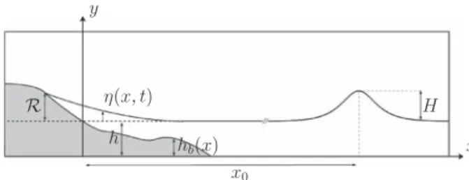
w,respectively.Inthe present method,no interface reconstruction step is employed soFig. 1. Schematic view of the set-up. The solitary wave of amplitude H and depth h is initially placed at x 0 . The vertical position of the air-water interface is h + ηwhile
that of the intersection point between the air-water interface and the immersed boundary is y = h + R , R being the run-up elevation.
the numerical thickness of the interface is not strictly zero, but typically spreadsoverthree gridcells[42].Eqs.(1)-(3)aresolved throughouttheentirecomputationaldomain,includingtheactual fluiddomainandthespaceoccupiedbythesolid.
2.2. Modelingoftheimmersedsolid
Following the IBM method [41], the interaction between the fluid andthe immersedbody is carried out by the addition ofa volumeforce termfin(1).Wefirstdefineasolidvolumefraction
α
(x)accountingforthepresenceoftheimmersedsolid.Thevalueoftheparameter
α
issetto1inthesolidregionand0inthefluid region.Atransitionregionisintroduced,whereα
valuesarelaying between0and1.Hereweconsidertheparticularcaseoffixed bot-tom orbottom-seatedobstacles.Assuming thatthe bottomshape is described by a function hb(x) (see Fig. 1), we define the solid volumefractionas[41]α
(
x)
= 12n
1− tanh³
y− hb(
x))
λη
i1
´o
(4)λ
=|
nx|
+|
ny|
+|
nz|
(5)η
i=0.065(
1−λ
2)
+0.39 (6)wheren=
(
nx,ny,nz)
isthenormaloutwardunitvectoratthe sur-face,η
i isa parameter controlling thethickness ofthe transition regionand 1isacharacteristicgridsize(1
=√21
xfora2D uni-formgrid).Theforcefisthendefinedasf=
α
Vs− eV1
t , (7)where 1t is the time stepused for thetime-advancement, Vs is thelocalvelocityimposedinthesolidobject(Vs=0here),andV˜
isanintermediatevelocityfieldwithoutconsideringtheimmersed object.Formoreprecision,seeSection2.4.
2.3. Timesteppingandspatialdiscretization
Eqs.(1)–(3)are solvedon astaggeredCartesiangridfollowing a finite-volumeapproach[43].Thetime integrationof(1)and(2)
is performedvia a third-orderRunge–Kutta methodforall terms except the viscous term for which a second-order semi-implicit Crank–Nicolsonscheme isused[44].Theincompressibility condi-tion (2) is satisfied atthe end ofeach time step through a pro-jection method. The transport equation of volume fraction (3)is solved by using a modified version of the flux-corrected trans-portschemeproposedbyZalesak[45].Domaindecompositionand Message-Passing-Interface(MPI)parallelizationisperformedto fa-cilitatesimulationoflargenumberofcomputationalcells.
2.4. Summaryofthetime-advancementprocedure
The time-advancementprocedure ofthepresent coupled VOF-IBM method within a time-step is described in the following,in thespecificcaseofafixedimmersedobject.
1.Atthebeginningofthetimestep,thedivergence-free veloc-ityfieldVn,volumefractionCn,pressurePn−1/2 inthefluid areknown,wherenreferstothetimestep.
2.Cn+1 iscomputedby solving(3),andsecond-order approx-imations ofthevolumefractionCn+1/2 attime (n+1/2
)1
t arecomputedusingCn+1/2=
(
Cn+Cn+1
)
/2,andusedto es-timatefluiddensityandviscosityinEq.(1).3.A Mixed Runge–Kutta/Crank–Nicolson loop (k=1,2,3) is used to compute the velocity field predictor bVn+1, taking intoaccountthepresenceofthesolidbodybutnot respect-ingthedivergencefreecondition.
3a. Computation of the intermediate velocity field eVk without consideringfluid-solidinteraction:
e Vk − bVk−1
1
t =SM, (8) with SM=γ
kN(
bVk−1)
+ζ
kN(
bVk−2)
+(
α
k+β
k)
L(
bVk−1)
−(
α
k+β
k)
³
1ρ ∇
P n−1/2 − g´
(9) whereN(resp.L)isthenon-linear(resp.linear)operatorfor theadvective(resp.viscous)terms.α
k,β
k,γ
kandζ
karethe Runge–Kuttacoefficients.ThevelocitypredictorbVkisinitial-izedwiththevelocityfieldattheprevioustimestep. 3b.Computationofthevelocityfieldwhichincludesthe
contri-butionofthefluid-solidcouplingtermfk(thecalculationof whichdoesnotmakeuseofaninternalloop)as
fk =
α
−eV k1
t , (10) b Vk − bVk−11
t −β
kL(
bV k − bVk−1)
=SM+fk. (11) 3c. Fork=3,bVn+1 isthenobtained.4.InordertoverifyEq.(2),aPoissonpseudo-equationisthen solvedtogetthepotentialauxiliaryfunction 8n+1 as
∇
·(
1ρ ∇
8
n+1
)
=
1
1t∇
· bVn+1. (12) 5.The pressure Pn+1/2 and the divergence-free velocity Vn+1 arethenobtainedfromthepotentialauxiliaryfunction 8n+1Pn+1/2 =Pn−1/2 +
8
n+1, (13) Vn+1 =bVn+1 −1
ρ ∇
t8
n+1. (14) 6.Returntostep1. 3. ResultsIn the following sections, the numerical method described aboveisappliedtothestudyofthepropagationofasolitarywave over bottoms of various shapes, namely a semi-cylinder, a slop-ing beach and a natural beach. A schematic view of the set-up is shown in Fig.1. The solitary wave of amplitudeH ina depth h movestoward theleft witha phasespeed c.We define the di-mensionless amplitude
ǫ
asǫ
=H/h.An immersedobjectmaybe includedinthefluiddomainandisrepresentedbythegrayregion in Fig.1. The solid body mayeitherbe immersed orsubmerged.Inthelattercase(asrepresentedinFig.1) thebodyisincontact withairandwater.Rdenotestherun-upelevation.
Allthe computations are initialized witha solitary wave cen-teredatthelocationx=x0usingasecond-orderaccurate analyti-calprofilegivenbyGrimshaw[46].Theinitialfreesurfaceposition
η
(x,0)isgivenby:η
(
x,0)
h =
ǫ
s2
−34
ǫ
2s2q2+O(
ǫ
3)
(15) where s=sech[γ
(
x− x0)
], q=tanh[γ
(
x− x0)
] andγ
=p
(
3ǫ
/4)
/h. The phase velocity of the solitary wave is given by c=cp³
1+1 2ǫ
− 3 20ǫ
2´
+O(
ǫ
3)
, (16) where cp=p
gh. The initial velocity field is also given by Grimshaw[46]. Since the analytical solution mentioned above is established using the potential flow assumption, in all the cases presentedherea transitoryphaseisobserved atearly timesuntil theboundarylayerisdevelopedatthebottomwall.
In the present configuration, the wave dynamics depends on the dimensionless amplitude
ǫ
=H/h and the Reynolds number heredefinedas[47] Re=r
4 3 cphǫ
3/2ν
. (17)Thedensityratioandviscosityratioare heldfixedat
ρ
w/ρ
a= 1000andµ
w/µ
a=55,whileǫ
andRearevaried.Physical quanti-tiesaremadedimensionlessusinghandcaslength andvelocity scales, respectively, andare denoted by an asterisk. In particular, wedefinethedimensionlesstimet∗=tc/handthedimensionless coordinates,x∗=x/handy∗=y/h.In thefollowing, only two-dimensional computations are per-formed and no turbulence model is used. Thus, low values of Reynolds number are employed in order to guarantee the preci-sionoftheresultsandthestabilityofthecomputations.Numerical resultspresentedinthispapercomefromfourdistinct computa-tions corresponding to four different physical configurations. For eachcomputation,thedimensionsandrefinementofthegridhave beencarefullychosen inordertoguaranteean optimalresolution oftheflowandtopreventsideeffects.Thenumericalpropertiesof thegrids aresummarizedinTable1.The timestepisupdated at each iterationto guaranteethe stability condition ofthe numeri-calschemes.Independentlyofthiscondition,thetimestepiskept below a maximum value of 1t∗≤ 2.5× 10⁻³ in order to ensure thetemporalprecisionofthecomputations.Detailsonthe conver-gencepropertiesofthecomputation inthe caseofapropagating solitarywave overofbottom-seatedsemi-circularcylinderare in-cludedinthefollowingsection.
3.1. Propagationoverabottom-seatedsemi-circularcylinder
Asemi-circularcylinderof radiusR∗=0.3isplaced atthe lo-cation (x∗p=0,yp∗=0
)
in the domain asan immersed boundary.Periodicboundaryconditionsareimposedalongtheverticalwalls whileano-slip(resp.free-slip)conditionisimposedatthebottom (resp.top)boundary,forthevelocity.Azeronormal-gradient con-ditionisimposedforthevolumefractionCatboththebottomand thetopboundaries.
Fig. 2 shows the computational grid around the immersed boundary. A solitary wave of amplitude
ǫ
=0.3 is initialized at x∗=14,i.e.farenough fromthecylindersoastoensurethat the transitory phase of boundary layer development takes place be-forethe wave beginsto interact withthe cylinder. The Reynolds number ofthe solitary wave is Re=210. In thissection, the re-sultsarecompared,whenpossible,tothoseofKlettnerandEamesTable 1
Summary of the computational grids used in the present study. Note that in irregular grid regions the grid size varies linearly.
Case nx × n y Range Grid spacing
Semi-circular cylinder 2048 × 128 −18 < x ∗< −5 . 2 1x∗= 1 / 32 −5 . 2 < x ∗< −4 . 8 1/64 < 1x∗< 1/32 −4 . 8 < x ∗< 4 . 8 1x∗= 1 / 64 4.8 < x ∗< 5.2 1/64 < 1x∗< 1/32 5.2 < x ∗< 30 1x∗= 1 / 32 0 < y ∗< 2 1y∗= 1 / 64
Sloping beach non-breaking case 2696 × 80 −3 . 56 < x ∗< −1 . 56 1/120 < 1x∗< 1/10
−1 . 56 < x ∗< 10 . 4 1x∗= 1 / 120
10.4 < x ∗< 76.4 1/10 < 1x∗< 1/120 0 < y ∗< 1 1/32 < 1y∗< 1/120
1 < y ∗< 2 1/120 < 1y∗< 1/32
Sloping beach breaking case 2354 × 158 −19 . 5 < x ∗< −6 . 3 1/100 < 1x∗< 1/10
−6 . 3 < x ∗< 9 . 7 1x∗= 1 / 100 9.7 < x ∗< 38 1/10 < 1x∗< 1/100 0 < y ∗< 0.7 1/32 < 1y∗< 1/100 0.7 < y ∗< 1.8 1y∗= 1 / 100 0.7 < y ∗< 2.5 1/100 < 1y∗< 1/32 Natural beach 2038 × 152 −4 < x ∗< 12 1 / 10 < 1x∗= 1 / 100 12 < x ∗< 36 1/10 < 1x∗< 1/100 0 < y ∗< 0.7 1/32 < 1y∗< 1/100 0.7 < y ∗< 1.8 1y∗< 1/100 0.7 < y ∗< 2.5 1/100 < 1y∗< 1/32
Fig. 2. Computational grid in the vicinity of the immersed boundary. The semi cir- cular cylinder is materialized by the isolines of solid volume fraction α= 0 . 5 (solid line), α= 0 . 05 and α= 0 . 95 (dashed lines).
[3]whoperformedadirectnumericalsimulationofasolitarywave interactingwithasemi-circularcylinderusinganALEmethodona two-dimensional body-fittedgrid.Theirsimulationswere realized using3× 106 cellsapproximately.Inthepresentwork,2.5
× 105 gridpointareused.
Fig.3showstheevolutionofthefreesurface(C=0.5)forboth thepropagationovera flatbottomandoverasemi-circular cylin-der. Thefree-surfaceisobservedtobe mostlyundisturbed bythe presenceoftheimmersedobject.Wenoteinpassingthepresence ofaweaklyreflectedwaveaftert∗≈ 14 = x∗
0/c∗inthecaseofthe semi-circularcylinder.
Inordertopredictthewave-bottominteraction,itisimportant toaccurately describetheflow motioninthevicinity ofthesolid boundary.InFig.4,snapshotsofthevorticityfieldnearthe cylin-derarepresentedatdifferenttimesduringthepassageofthe soli-tarywave.Fig.4aconfirmsthattheflowisessentiallyirrotational exceptnearthebottomwall andtheimmersedcylinder.The vor-ticity on the top left corner of Fig. 4c and4 d isrelated to the shearlayernearthefreesurface.Theregions ofnegative vorticity alongthecylindersurfaceindicatesthepresenceoftwoseparation points :oneupstream tothecylinderandoneclosetothetopof
Fig. 3. Evolution of the free-surface, materialized by the iso-contour C = 0 . 5 , of a solitary wave propagating over ( ) a flat bottom and ( ) a circular cylinder. The cylinder is at the location x ∗= 0 and the initial location of the wave’s crest is x∗
0 = 14 . Note that the vertical scale is arbitrary.
the cylinder. The latteris responsiblefor theformation ofa vor-texattheleesideofthecylinder,whichisshedfromthecylinder (Fig.4b)whileothervorticesaregeneratedattheequatorandare then subjectto complexvortex interaction (Fig. 4c and4d). The presentevolutionofthevorticityfieldaroundtheimmersed cylin-derisinreasonableagreementwiththatobtainedbyKlettnerand Eames[3](seetheirFig.6).
The streamlines around the semi-cylinder are presented in
Fig.5aatt∗=14.4.TheresultsareveryclosetothoseofKlettner andEames[3](Fig.5b),withthepresenceoftworecirculating re-gionsrespectivelyupstreamanddownstreamtothecylinder.Some characteristics of theses regions are definedin Fig. 5c and com-pared forboth studies inTable 2. Agood agreement isobserved betweenthetwocomputations.
The dimensionlessdragforce overthecylinderisestimatedas
F∗ x = Fx 1 2
ρ
lc2R , (18) Fx= Z Spρ
lf· exdS, (19)withfbeingdefinedin(7)andSp beingthesurfaceofthe semi-cylinder.ThetemporalevolutionoftheforceFx∗isplottedinFig.6a
Fig. 4. (Colour online) Dimensionless vorticity field in the vicinity of a bottom-seated semi-circular cylinder during the passage of a solitary wave of amplitude ǫ= 0 . 2 at
t∗= 17 . 6 (a), 22.4 (b), 28.5 (c) and 36.3 (d). Here the vorticity is made dimensionless by c / h and the iso-contours are linearly distributed in the range [ −0 . 6 , 0 . 6] . The actual
range of vorticity in each snapshot is [ −4 . 1 , 4 . 9] (a), [ −3 . 7 , 3 . 1] (b), [ −3 . 3 , 1 . 2] (c) and [ −2 . 7 , 0 . 8] (d).
Fig. 5. Streamlines in the vicinity of the cylinder at t ∗≈ 14.4, showing the forma-
tion of two recirculation regions stemming from the passage of the solitary wave: (a), present study. The semi-circular cylinder represented by a black disk is materi- alized by α= 1 ; (b), results of [3] using a boundary-fitted approach; (c), schematic view of the characteristic lengths and angles used in Table 2 of the recirculation regions.
Table 2
Characteristic lengths and angles of the recirculation regions displayed in Fig. 5 . The results of [3] who used a well-resolved boundary-fitted approach are taken as reference for comparison.
Study l1 /R l2 /R α1 α2
Klettner and Eames [3] 1 .26 1 .25 5 .9 ° 27 .4 °
Present study 1 .33 1 .36 5 .8 ° 29 .2 °
Error (%) 5 .6 8 .8 2 .3 6 .7
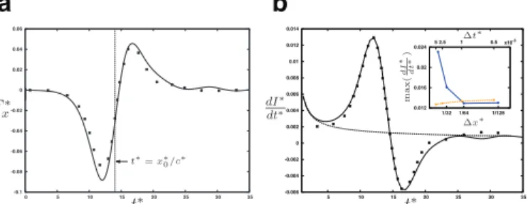
andcomparedwiththatofKlettnerandEames[3].Thedragforce is positiveduring the firstinstantsofthecomputation, whilethe solitarywaveispropagatingtowardthecylinder.Afterreachingan extremum att∗≈ 12,theforcethenrapidlybecomespositiveand reaches anotherextremum beforeit goes downto zero. This be-havior suggests that the drag force is mostly due to hydrostatic pressuregradientbelowthewave.However,inanidealized poten-tialflow, thehydrostaticpressuregradientwouldresultinaforce Fx∗whichvanishesexactlywhenthecrestpassesoverthecylinder (i.e. att∗=x∗
0/c∗), with equalpositive and negative peaksbefore andafterthistimeinstance.InFig.6aitisobservedthatFx∗does notvanishatt∗=x∗
0/c∗andthatthenegativepeakisalmosttwice higher thanthe positiveone. Thiscan be interpretedasa conse-quence of thepresenceof theviscous boundarylayers. In partic-ular,thepresenceofthelargedownstreamrecirculatingregion,as showninFig.5,isexpectedtoinvolveanetnegativedragforce.
The dimensionlessspatially-averaged horizontalmomentumof thesolitarywaveisdefinedasI∗=I/cM,whereMisthemassper unitlengthofthewave
M=
Zxmax
xmin
ρ
lη
dx, (20)andIisthewavemomentum,
Fig. 6. Solitary wave propagating over a semi-circular cylinder: Evolution of (a) the drag force F ∗
x exerted by the fluid on the cylinder, and (b) the time derivative of the spatially-averaged horizontal momentum: ( ), present study; ( ∗), results of [3] ; ( ), present results for the case of a solitary wave propagating over a flat bottom. The variation of the maximum value of dI ∗/ dt ∗ as a function of the time
step ( ) and the grid size ( ) in the region the cylinder is included in (b) to show the convergence of the computation. Here, I ∗= I/cM.
I= Zη 0 Zxmax xmin
ρ
lUdxdy. (21)Herexmin andxmax denotethepositions ofthelateralboundaries ofthecomputationdomain.
The interaction betweenthe wave andthe solid body is now observedviathevariationofdI∗/dt∗(Fig.6b).Inthecaseofaflat bottom,one canseea transitoryregime duetotheadaptation of theidealizednon-viscousinitialconditiontothebottomboundary condition.Inpresenceofthecylinder,thetimehistoryofdI∗/dt∗is verysimilartotheevolutionofF∗
x.Apositiveandanegativepeak areobserved,respectivelycorrespondingtothenegativeand posi-tivepeakofFx∗.Aftert∗≈ 25thewaveisnotinteractinganymore withthecylinder anddI∗/dt∗is thesame asinthe caseofa flat bottom.Theoriginofthebumpobservedatt∗ ≈ 30inFig.6has notbeenidentifiedso far,butmaybe relatedto thevorticity dy-namicsnearthecylinder.Duringallthecomputationagood agree-ment withthe resultsof KlettnerandEames [3]is observed de-spitethedifference inthecomputation methodsandinthe num-berofcellsemployed.
The variation of the maximum value of dI∗/dt∗ as a function of the time step andthe grid size in the region of the cylinder is includedin Fig. 6b to show the convergence propertiesof the computation.Theresultgreatlyvarieswiththegridsizewhileitis lesssensitivetothe timestep.So far,theanalysishasbeendone on the basis of numerical results obtainedwith 1x∗=1/64 and
1
t∗=2.5× 10⁻³.Itisseenthatthecomputationiswellconverged withthissetofnumericalparameters.The above observations show that the use of the present VOF-IBM approach is relevant for the numerical investigation of wave-bottom interaction problems. The method is able to accu-ratelycaptureimportantflowfeatureslikeflowseparationand vor-texsheddingwhichinfluencethewaveloadingonthebody,while keepingareasonablenumberofgridpoints.
3.2. Run-upofasolitarywaveonaslopingbeach
Intheprevioussection,themodelingofthefreesurfacehasnot beena centralissueasthe waveonlyweakly deformsduetothe presenceofthecylinder.Inthissection,we considertheshoaling ofasolitarywave onaslopingbeach,whichintroducesadditional complexitydueto(i)thepresenceofatriplepointatthecoastline and (ii) the occurrence of strong free-surface deformations with possiblewavebreaking.
Asolitarywaveofamplitude
ǫ
andinitiallycenteredatx∗ 0=50 propagatestowardtheleftbeforeitsencountersatx∗p=1/tan(
β
)
a slopingbeachforminganangleβ
=arctan(
1/19.85)
withthehor-izontalaxis.Free-slipboundaryconditionsareimposedatthe up-per horizontaland thevertical boundariesforthe velocity, while a no-slipboundarycondition isimposed atthebottom boundary. Zeronormal-gradientconditionsareimposed atallboundariesfor thevolumefractionC.
Wedefinethewave run-upRasthemaximumheightreached bythewedgeofwaterthatclimbsthebeach(seee.g.Fig.1). Syn-olakis[48]derivedasolutionbasedontheinviscidshallow-water theoryfortherun-upofanon-breakingsolitarywaveasafunction oftheamplitudeandtheslopeviz
R h =2.831
(
cotβ
)
1 2³
H h´
5 4 . (22)Healsostatedthattheoccurrenceofwavebreakingonlydepends on theseparameters. Histheoretical analysisallowedhim to pre-dict thecriticalamplitudeHc above which wave-breakingoccurs, namely
Hc
h =0.8183
(
cotβ
)
−109. (23)
We first consider a non-breaking solitary wave of amplitude
ǫ
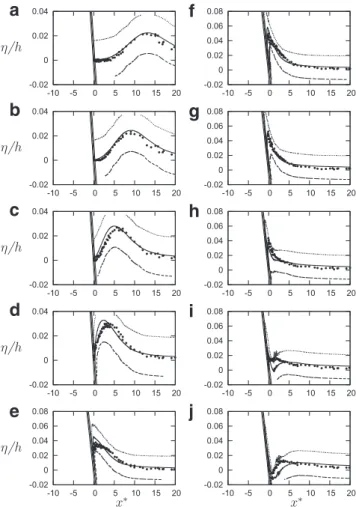
=0.019. The value of the Reynolds number defined in (17) is Re=335. The temporal evolution of the free-surface along the slope is presented in Fig. 7 together with the experimental data ofSynolakis [40].In ordertoestimate thenumericalthicknessof the free-surface relative to the wave amplitude, the interface is represented by threeiso-lines ofvolume fraction. It appears that forsuch a smallamplitude, the thicknessof thefree-surfaceand thewave amplitudeareofthesameorderofmagnitude.In prac-tice,thefree-surfaceisconsideredtobelocalizedalongtheiso-line C=0.5.ThepresentnumericalsolutiondisplayedinFig.7showsagood agreementwithexperiments.Thedynamicsoftheshoalingiswell described,exceptatlatetimesduringthebackwash(80≤ t∗≤ 90) forwhich thereisa slighttime delaybetweenthe numerical so-lution and the experimental data. In addition, the run-upof the waveisslightlyunder-predictedbythecomputation,sincewe ob-tain avalue ofR/h=0.059(calculatedwiththeiso-valueC=0.5 ofthe watervolume fraction)instead ofR/h=[0.076− 0.078]in theexperimentsofSynolakis.Eq.(22),basedonaninviscidtheory, predictsarun-upR/h=0.089.
Whenthewavepropagatesoveranentirelyimmersedbody,as in the case of the bottom-seated cylinder (see Section 3.1), the air/waterandwater/bottom interfacesnever intersect contraryto thepresentcasewherebothinterfacesintersect.Thevolume frac-tion as well as the sloping beach near this point are shown in
Fig. 8.This figure showsthat the interface is smeared inthe re-gionoftherun-up.Thissmearingisinherentofthefront-capturing
Fig. 7. Run-up of a solitary wave on a slope of angle β= arctan (1 / 19 . 85) with
ǫ= 0 . 019 and Re = 335 . The free-surface for the present method is represented by iso-lines of C = 0 . 1 ( ), 0.5 ( ) and 0.9 ( ); ( ), experiments of Syno- lakis [48] . The immersed boundary is represented by iso-lines α= 0 . 1 , 0.5 and 0.9. Profiles are shown at (a) t ∗= 38 . 01 , (b) 43.60, (c) 50.30 , (d) 55.89, (e) 61.48, (f)
68.19, (g) 72.66, (h) 78.25, (i) 82.72 and (j) 88.31. Note that the frames have been stretched in the vertical direction for sake of clarity.
Fig. 8. Run-up of a non-breaking solitary wave on a sloping beach. Visualization of the fluid and solid volume fraction fields in the swash zone at t ∗= 62 . 60 . Both
quantities are respectively represented with iso-contours of C = 0 . 1 , 0.5, 0.9 (solid lines) and α= 0 . 1 , 0.5 and 0.9 (dashed lines).
methodswithnointerfacereconstructioninregionsofhigh shear-stress[42].Weverifiedthatthesmearingoftheair-waterinterface was notduetothepresenceoftheimmersed-boundary,sincethe samedistributionofvolumefractionwasfoundwhenthebeachis treated by a boundaryfittedgrid witha no-slipboundary condi-tion(notshownhere).
Increasing the wave amplitude while keeping the same an-gle for the sloping beach leads to the breaking of the solitary wave.Theoccurrenceofbreakingisintrinsicallylinkedtothe non-linearity of the wave propagation. During shoaling, the informa-tion propagates faster at the top of the wave, resulting in high velocity gradients in the vicinity ofthe crest andincreasing tur-bulence, as observedin the Particle ImageVelocimetry measure-ments of Kangetal. [49]. Thisprocess may then be followedby the formation ofa plungingjet which involvestrong mixingand
Fig. 9. Run-up of a breaking solitary wave with ǫ= 0 . 3 and Re = 210 , materialized by the volume fraction of water.
Fig. 10. Run-up of a breaking solitary wave on a slope of angle β= arctan (1 / 19 . 85)
with ǫ= 0 . 3 and Re = 210 . The immersed boundary is represented by iso-lines of
α= 0 . 1 , 0.5 and 0.9 while the free-surface obtained from the simulations is mate- rialized by the iso-contour C = 0 . 5 : ( ) present method with the beach treated as an immersed boundary; ( ) experiments of [40] ; ( ) present method with the beach treated as a body-fitted boundary with a no-slip condition for the velocity. Profiles are shown at times (a) t ∗= 23 . 91 , (b) 28.97 , (c) 34.64, (d) 57.25, (e) 68.58
and (f) 79.91. Note that the frames have been stretched in the vertical direction for clarity.
the generationofturbulence.Recall thathere, we intendtosolve all thespatial andtemporalscales oftheflowbymeans ofdirect numericalsimulation,i.e.withoutusinganyturbulencemodel.The limitedcomputational resourcesforce ustochoosemoderate val-uesoftheReynoldsnumber.
We performed a simulation of the propagation of a solitary waveofamplitude
ǫ
=0.3andReynoldsnumberRe=210running upaslopingbeachwithanangleβ
=arctan(
1/19.85)
.Asthe am-plitudeǫ
ofthewaveiswellabovethecriticalamplitudegivenbyEq.(23)Hc/h=0.03,thewaveisexpectedtobreakduringthe run-up.InFig.9,weplotthetemporalevolutionofthewaveshape. De-spitethemoderatevalueoftheReynoldsnumber,onecanobserve a typicalplungingbreakdownofthe wave.InFig.9a,a plunging jet impactsthefree-surface, causingtheformationofasecondary jet(splash-up,Fig.9b).Thisresultsinmixingbetweenairand wa-ter asobserved inFig.9cand9 d.Thisisin agreementwith ex-perimentalobservationsofBonmarin[50].
The free-surface position during the run-up (C=0.5) is com-pared with the experimental results of Synolakis [40] in Fig.10. Note that in the experiment, Re≈ 5 × 10⁴. A very good agree-mentisobservedfort∗≤ 35,i.e.beforethecollapsingofthebore andtheejectionofthejet[51].Att∗=57.25,therun-upis
under-predictedbythecomputationincomparisonwiththeexperiments. Inaddition,the borelocatedatx∗=3fort∗=70− 80 inthe ex-periments dueto thebackwash flow isnot observed inthe sim-ulation. Note however, that this region connecting the backward flowing thin layer of waterand the deeper wateris likely to be subjecttostrongmixingandairentrainment,thus increasing the experimentaluncertaintiesofthefree-surfacemeasurements.
Inordertoassessthe influenceoftheimmersedboundary on the solution, we performed another computation for which the beach is treated as a boundary-fitted grid with a no-slip (resp. zero-normal gradient) condition imposed for the velocity (resp. volume fraction). The profiles of the free-surfacerunning up the body-fittedbeachisshowninFig.10(trianglesymbols).Itisfound that the free-surface profile is nearly identical to that obtained with the simulation for which the beach is modeled via an im-mersed boundary. Therefore,one mayconclude that the discrep-ancybetweenthesimulationandtheexperimentisnotduetothe immersed-boundarymodeling.
The discrepancy observed between the numerical simulation andtheexperienceislikelyduetothedifferenceofReynolds num-bers. Recall that Re=210 (Re≈ 5× 10⁴) inthe simulations (ex-periments).ThesomewhatlowvalueoftheReynoldsnumber em-ployedinthecomputation mayleadtoan increasedenergy dissi-pation in the regions of highvelocity gradients especially at the air-water interface and more importantly along the wall of the sloping beach. During therun-up ofthe water front,the viscous dissipation becomes significant in the thin layer of water which is subject to strong shear at both the air-water interface and at thewall.Inthecaseofthinliquidfronts propagatingalonga hor-izontal wall, Bonometti et al. [52] showed that the wall friction could leadto a decreaseofthe front velocityof upto 50% espe-cially when the density ratio of the current to ambient is large, asin thepresent case. Thisis inline withthe fact that the dis-crepancybetweenthesimulationsandtheexperimentinFig.10is probablydue to viscous friction (alongthe sloping beach) which isartificiallyincreasedby thesomewhat low value ofthechosen Reynoldsnumber.
Anindirectconfirmation ofthispointisgiveninFig.11where thebeachisstilltreatedbyabody-fittedmeshbutwithafree-slip boundarycondition (i.e.noviscous stress attheboundary). Here, we observed a close agreement withexperiments. The dynamics ofboth therun-upandrundown is well described,including the formationofaboreduring thebackwash,eventhoughitsposition is slightlyshifted toward the shore (Fig. 11e).This confirmsthat thesmallrun-upofthecomputedwavefrontinFig.10isrelated totheartificiallylargewallfrictionalongthebeachandnottothe factthatthebeachismodeledbyanimmersedboundary.
0 0.2 0.4 -10 -5 0 5 10 0 0.2 0.4 -10 -5 0 5 10 0 0.2 0.4 -10 -5 0 5 10 0 0.2 0.4 -10 -5 0 5 10 0 0.2 0.4 -10 -5 0 5 10 0 0.2 0.4 -10 -5 0 5 10
Fig. 11. Same as Fig. 10 : ( ) experiments of [40] ; ( ) present method with the beach treated as a body-fitted boundary with a free-slip condition for the velocity .
Fig. 12. Visualization of the initial state of the simulation of the run-up of a solitary wave on a natural beach. The two fluid phases are represented in gray (water) and white (air), respectively and the immersed boundary (i.e. the beach) is represented by the solid black line. Here, the wave amplitude is ǫ= H/h = 0 . 27 .
Insummary,theabove observationsallow usto concludethat (i)theVOFmethodisefficientindescribingcomplexinterface de-formations includingplunging wave breaking, the dynamics of a free-surface of smallamplitude beingwell capturedeven with a moderatespatialresolutionofthefreesurface;(ii)theIBMisable to reproduce wave-bodyinteractions including non-breaking and breaking waves running up a sloping beach; (iii) a low value of theReynoldsnumberleadstolargeviscouswallfrictioninsidethe climbinglayeroffluidalongtheslope.Settingafree-slipboundary conditionalongthebeachpermitstogetgoodagreementbetween moderate-Resimulationandwaterwaveexperiments.
3.3. Run-upofasolitarywaveonanaturalbeach
Sofar thepresent numericalmethodwasapplied toacademic cases usually considered as paradigms of more complex natural configurations. Theadvantage oftheimmersed boundarymethod ascomparedto approachesusingabody-fittedgrid isthat itcan be applied to arbitrary bottom geometries. In order to illustrate the potential of such a method, we now focus on the run-upof abreakingsolitarywaveonanaturalbeach.
Caplain [53] performed a series of experiments in order to study sediment transport and sea bed morphology induced by a harmonic wave forcing. Different types of beach profile were obtained depending onthe energyof theincoming waves.These profiles were mostlytwo-dimensional, that isinvariant along the horizontaldirectionperpendiculartotheincomingwaves.Forour numerical simulation, we chose one profile as an example of a naturallyshapedbeach(seeFig.4.11in[53]).Avisualizationofthe beach modeled via an immersed boundary in the computational domainispresentedinFig.12.Notethatweextendedtheleftpart ofthebeachbyaplateau(x∗≤ 2)inordertopermitoverflow.
Thesolitarywaveisinitializedwithanamplitude
ǫ
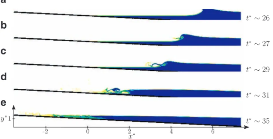
=0.27 cor-responding toa Reynoldsnumber Re=360.Snapshots ofvolume fractionatdifferenttime duringthe run-upareshowninFig.13. Att∗=26.1,thewavehaspassedthebarandlostitsinitialshape, mostly due to the blocking effect caused by the topographicalbump. At 28.6≤ t∗ ≤ 29.5, a bore is formed which collapses at
t∗≈ 30.2.Inthepresentcase,therun-upofthewave islargeand induces anoverflowvisibleatt∗=33.9.Notethatthisoverflowis likelytobe underpredictedduetothelow valueoftheReynolds numberusedhere,asdiscussedintheprevioussection.
The profile ofthe freesurface exhibits other complex interac-tions between the wave andthe topography. An interesting fea-tureisthepresenceofadeformationofthefreesurfaceontheleft side ofthebar(x∗ ≈ 3.5)whichappears att∗=28.6andpersists for along time afterthe passageofthe crest (untilt∗=40).The depression islocatedabovea strongdecreaseofthebottomfloor attheleftofthebump.Thisperturbationremainsstationaryuntil theprimarywavereachesitsmaximumrun-updistance,andthen propagates back offshore (33.9 ≤ t∗ ≤ 41.3).The Froude number associatedwiththesolitarywavecanbeestimatedbyF=U /
p
gh, U being the characteristic velocity of the solitary wave namely U =ǫ
p
gh,which leads toF=ǫ
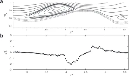
=0.27. Inaddition, theblockage factordefinedastheheightratiobetweenthebarandthefree sur-faceisapproximately80%,here.Similarfeatureswere observedin subcriticalfreesurfaceflowsoveranobstructionwithahigh block-agefactor,asin[54]and[55]forexample.A typical featureof the flowinduced by the run-upis shown in Fig. 14.The flow structure in the vicinity ofthe bar, which is oriented from rigth to left, is characterized by two recirculation regions. Onthe lee side of thebar, we observe the formation of a strong vortex which persists until it is swept down when the wave beginstorundown (notshown).Theflowpatterndescribed herehasagreatimportanceintermsofbedloadtransport,asone wouldexpectsuch structurestoresultinasharpeningofthebar. Inordertoquantitativelyillustratethisfeature,weshowinFig.14
the bottomshearstress
τ
b=µ∂
ut/∂
n,interpolatedontheisolineα
=0.5inthe vicinity ofthe bar. Here ut andn respectively de-note thetangential velocity andthe direction normalto the bot-tom.Weobservethattwoextremaofoppositesign(τ
b≈ ±1)are present onbothsidesofthetopofthebar.Aroughestimationof the Shields parameter 2=τ
b/(
ρ
s−ρ
)
gD basedon the character-isticsedimentsdensityρ
s anddiameterDoftheparticlesusedinFig. 13. Run-up of a breaking solitary wave on a natural beach. Snapshots of volume fraction at t ∗= 26 . 1 (a),28.6 (b), 29.5 (c), 30.2 (d), 33.9 (e) and 41.3 (f). Note that the
aspect ratio of the snapshots is here equal to 1.
Fig. 14. Run-up of a breaking solitary wave on a natural beach. Streamlines (a) and bottom shear stress (b) in the vicinity of the bar at t ∗= 31 . 6 .
the experiments of[53] gives 2 ≈ 0.2 for
τ
b=1. Considering a critical value 2c=0.1 abovewhich aparticlesuspension maybe expected, the present flow would resultin a sediment transport frombothsidesofthebartowardthetop.Asimilarapproachhas beenusedby [56]inordertosimulatethemorphodynamicinan open-channelbend.4. Summaryandconclusions
The aim of thiswork was to demonstrate the capability of a coupledVOF-IBMnumericalmethodtoaccuratelyreproducewave shoaling onsimpleandcomplexshapedbottoms.Thepropagation ofasolitarywaveoverasemi-circularcylinderhasbeensimulated showingthattheIBMwasabletoreproducesomekeyfeatures of
fluid-bodyinteractionsuchasflowseparationandvortexshedding. Quantitativecomparisonwiththeresultsof[3]showsthattheflow dynamicsiswelldescribedevenifthespatialresolutionisone or-derofmagnitudelowerthanthatusedbytheseauthors.
Thepresentapproachwasthenappliedtotherun-upofa soli-tary wave on a sloping beach where strong deformations of the free surface occur,including plungingwave breaking and genera-tionofsecondaryjets.Thelowvalue oftheReynoldsnumber em-ployedinthesimulationshasbeenidentifiedtobethecauseofan underprediction ofthe maximum wave run-up dueto an artifi-ciallyincreasedwallfrictionalongtheslopeofthebeach. Compar-isons withboundary-fitted simulations withno-slipand free-slip conditionalongthebeachslopehaveshownthat(i)theimmersed boundary is able to reproduce the no-slip condition along the
immersedboundaryand(ii)usingafree-slipboundaryenablesus toobtainagoodagreementwithexperimentalresultsdespitethe somewhatlowvalueoftheReynoldsnumber.
Finally,wepresenteda simulationoftherun-upofabreaking solitarywaveonanaturalbeachincludingthepresenceofabarin thebreakerzone.Weobservedthatcomplexinteractiontakeplace in this region. The free-surface dynamicsis characterized by the presenceofastationaryperturbationsimilartothoseobservedin channel flowsoveran obstacle,andtheformationoftwo recircu-latingregionsaroundthebar’screstassociatedwiththeformation ofstrongvortices.
ThecapabilityoftheIBMtodealwitharbitraryshaped bound-arieswidelyincreasesthediversityofproblemswhichcanbe stud-iednumerically.Then,asboththeVOFmethodandtheIBMcanbe straightforwardlyappliedto three-dimensionalconfigurations, nu-merical studies of wave shoaling over variable topography along bothdirectionscanbeperformed.
References
[1] Liu Y , Dommermuth D , Yue D . A high-order spectral method for nonlinear wave body interactions. J Fluid Mech 1992;245:115–36 .
[2] Lin M , Huang L . Study of water waves with submerged obstacles using a vortex method with Helmholtz decomposition. Int J Numer Meth Fluids 2009;60:119–48 .
[3] Klettner C , Eames I . Momentum and energy of a solitary wave interacting with a submerged semi-circular cylinder. J Fluid Mech 2012;708:576–95 . [4] Longuet-Higgins M , Cokelet E . The deformation of steep surface waves on wa-
ter. I. a numerical method of computation. Proceedings of the Royal Society London A 1976;350:1–26 .
[5] Dold J , Peregrine D . An efficient boundary integral method for steep unsteady water waves. Numer Meth Fluid Dynam II 1986:671–9 .
[6] Chian C , Ertekin R . Diffraction of solitary waves by submerged horizontal cylin- ders. Wave Motion 1992;15:121–42 .
[7] Grilli S , Subramanyan R , Svendsen I , Veeramony J . Shoaling of solitary waves on plane beaches. J Waterw Port C Ocean Eng 1994;120:609–28 .
[8] Dommermuth D , Yue D . A high-order spectral method for the study of nonlin- ear gravity waves. J Fluid Mech 1987;184:267–88 .
[9] Craig W , Sulem C . Numerical simulation of gravity waves. J Comput Phys 1993;108:73–83 .
[10] Bateman W , Swan C , Taylor P . On the efficient numerical simulation of direc- tionally spread surface water waves. J Comput Phys 2001;174:277–305 . [11] Nicholls D . Traveling water waves: spectral continuation methods with parallel
implementation. J Comput Phys 1998;143:224–40 .
[12] Liu Y , Yue D . On generalized Bragg scattering of surface waves by bottom rip- ples. J Fluid Mech 1998;297:297–356 .
[13] Smith R . An operator expansion formulation for nonlinear surface water waves over variable depth. J Fluid Mech 1998;363:333–47 .
[14] Iafrati A , Campana E . A domain decomposition approach to compute wave breaking (wave-breaking flows). Int J Numer Meth Fluids 2003;41:419–45 . [15] Grilli S , Harris J , Greene N . Modeling of wave-induced sediment transport
around obstacles. In: Proceedings of the 31st International Conference on Coastal Engineering; 2008. p. 1638–50 .
[16] Zhang Y , Peszynska M , Yim S . Coupling of viscous and potential flow models with free surface for near and far field wave propagation. Int J Numer Anal Model 2013a;4(3):256–82 .
[17] Lin M , Huang L . Vortex shedding from a submerged rectangular obstacle at- tacked by a solitary wave. J Fluid Mech 2010;651:503–18 .
[18] Pedersen G , Gjevik B . Run-up of solitary waves. J Fluid Mech 1983;135:283–99 . [19] Madsen P , Fuhrman D , Wang B . A Boussinesq-type method for fully non- linear waves interacting with a rapidly varying bathymetry. Coastal Eng 2006;53:487–504 .
[20] Hibbert S , Peregrine D . Surf and run-up on a beach: a uniform bore. J Fluid Mech 1979;95:323–45 .
[21] Zhang J . Run-up of ocean waves on beaches. California Institute of Technology, Pasadena, CA; 1996. Ph.D. thesis .
[22] Dodd N . Numerical model of wave run-up, overtopping, and regeneration. J Waterw Port C Ocean Eng 1998;124:73–81 .
[23] Titov V , Synolakis C . Modeling of breaking and non-breaking long-wave evolu- tion and run-up using VTCS-2. J Waterw Port C Ocean Eng 1995;121:308–461 . [24] Li Y , Raichlen F . Non-breaking and breaking solitary wave run-up. J Fluid Mech
2002;456:295–318 .
[25] Tang C , Chang J . Flow separation during solitary wave passing over submerged obstacle. J Hydraul Eng 1998;124:742–9 .
[26] Zhang D , Chwang A . On solitary waves forced by underwater moving objects. J Fluid Mech 1999;389:119–35 .
[27] Lo D , Young D . Arbitrary Lagrangian-Eulerian finite element analysis of free surface flow using a velocity-vorticity formulation. J Comput Phys 2004;195:175–201 .
[28] Zhao Q , Tanimoto K . Numerical simulation of breaking waves by large eddy simulation and VOF method. In: Proceedings of the 26th International Confer- ence on Coastal Engineering, 1; 1998. p. 892–905 .
[29] Hieu P , Tanimoto K , Ca V . Numerical simulation of breaking waves using a two-phase flow model. Appl Math Model 20 04;11:983–10 05 .
[30] Zhao Q , Armfield S , Tanimoto K . Numerical simulation of breaking waves by multi-scale turbulence model. Coastal Eng 2004;51:53–80 .
[31] Lubin P , Glockner S , Kimmoun O , Branger H . Numerical study of the hydrody- namics of regular waves breaking over a sloping beach. Eur J Mech B-Fluids 2011;30:552–64 .
[32] Chang K , Hsu T , Liu P . Vortex generation and evolution in water waves prop- agating over a submerged rectangular obstacle: Part I. Solitary waves. Coastal Eng 2001;44:13–36 .
[33] Lin P . A numerical study of solitary wave interaction with rectangular obsta- cles. Coastal Eng 2004;51:35–51 .
[34] Sue Y , Chen M , Hwang R . Interaction of nonlinear progressive viscous waves with a submerged obstacle. Ocean Eng 2005;32:893–923 .
[35] Peng W , Lee K-H , Mizutani N . Application of direct-forcing IB-VOF method to the simulation of wave deformation by submerged structures. J Coastal Res 2012;28(3):658–70 .
[36] Shen L , Chan E-S . Numerical simulation of fluid–structure interaction using a combined volume of fluid and immersed boundary method. Ocean Eng 2008;35(8):939–52 .
[37] Lee K-H , Mizutani N . A numerical wave tank using direct-forcing immersed boundary method and its application to wave force on a horizontal cylinder. Coastal Eng J 2009;51(01):27–48 .
[38] Zhang C , Zhang W , Lin N , Tang Y , Zhao C , Gu J , et al. A two-phase flow model coupling with volume of fluid and immersed boundary methods for free sur- face and moving structure problems. Ocean Eng 2013b;74:107–24 .
[39] Zhao X., Gao Y., Cao F., Wang X.. Numerical modeling of wave interactions with coastal structures by a constrained interpolation profile/immersed boundary method. Int J Numer Meth Fluids, in press.
[40] Synolakis C . The run-up of long waves. California Institute of Technology, Pasadena, CA; 1986. Ph.D. thesis .
[41] Bigot B , Bonometti T , Lacaze L , Thual O . A simple immersed-boundary method for solid-fluid interaction in constant- and stratified-density flows. Comput Fluids 2014;97:126–42 .
[42] Bonometti T , Magnaudet J . An interface-capturing method for incompressible two-phase flows. Validation and application to bubble dynamics. Int J Multi- phas Flow 2007;33:109–33 .
[43] Harlow F , Welch J . Numerical calculation of time-dependent viscous incom- pressible flow of fluid with free surface. Phys Fluids 1965;8:2182–9 . [44] Calmet I , Magnaudet J . Large-eddy simulation of high-Schmidt number
mass transfer in a turbulent channel flow. Phys Fluids (1994-present) 1997;9(2):438–55 .
[45] Zalesak S . Fully multidimensional flux-corrected transport algorithms for flu- ids. J Comput Phys 1979;31:335–62 .
[46] Grimshaw R . The solitary wave in water of variable depth. J Fluid Mech 1971;46:611–22 .
[47] Sumer B , Jensen P , Sorensen L , Fredsoe J , Liu P . Turbulent solitary wave bound- ary layer. In: Proceedings of the 18th International Offshore and Polar Engi- neering Conference; 2008. p. 775–81 .
[48] Synolakis C . The run-up of solitary waves. J Fluid Mech 1987;185:523–45 . [49] Kang D , Ghosh S , Reins G , Koo B , Wang Z , Stern F . Impulsive plunging wave
breaking downstream of a bump in a shallow water flum - Part I: Experimen- tal observations. J Fluid Struct 2012;32:104–20 .
[50] Bonmarin P . Geometric properties of deep-water breaking waves. J Fluid Mech 1989;209:405–33 .
[51] Mory M , Abadie S , Mauriet S , Lubin P . Run-up flow of a collapsing bore over a beach. Eur J Mech B-Fluids 2011;30(6):565–76 .
[52] Bonometti T , Balachandar S , Magnaudet J . Wall effects in non-boussinesq den- sity currents. J Fluid Mech 2008;616:445–75 .
[53] Caplain B . Étude expérimentale de l’érosion d’un massif de sable cohésif par une houle monochromatique. Institut National Polytechnique de Toulouse, France; 2011. Ph.D. thesis .
[54] Forbes L . Critical free-surface flow over a semi-circular obstruction. J Eng Math 1988;22:3–13 .
[55] Vigie F . Etude expérimentale d’un écoulement à surface libre au-dessus d’un obstacle. Institut National Polytechnique de Toulouse, France; 2005. Ph.D. the- sis .
[56] Khosronejad A , Kang S , Borazjani I , Sotiropoulos F . Curvilinear immersed boundary method for simulating coupled flow and bed morphodynamic interactions due to sediment transport phenomena. Adv Water Resour 2011;34(7):829–43 .

![Fig. 11. Same as Fig. 10 : ( ) experiments of [40] ; ( ) present method with the beach treated as a body-fitted boundary with a free-slip condition for the velocity](https://thumb-eu.123doks.com/thumbv2/123doknet/3103710.88050/9.892.245.664.117.423/experiments-present-method-treated-fitted-boundary-condition-velocity.webp)