Official URL
https://doi.org/10.1145/3341105.3373944
Any correspondence concerning this service should be sent
to the repository administrator:
tech-oatao@listes-diff.inp-toulouse.fr
This is an author’s version published in:
http://oatao.univ-toulouse.fr/26362
Open Archive Toulouse Archive Ouverte
OATAO is an open access repository that collects the work of Toulouse
researchers and makes it freely available over the web where possible
To cite this version: Baduel, Ronan and Ober, Iulian and Bruel,
Jean-Michel Modeling and verification method for an early evaluation
of Systems of Systems interactions.
(2020) In: 35th Annual ACM
Symposium on Applied Computing (SAC 2020), 30 March 2020 - 3
April 2020 (Brno, Czech Republic).
Modeling
and verification method for an early evaluation of
Systems
of Systems interactions
Ronan
Baduel, Iulian Ober and Jean-Michel Bruel
University of Toulouse / CNRS IRIT Laboratory Toulouse, France
first.last@irit.fr
ABSTRACT
This paper presents the results achieved while pursuing the verifi-cation and validation of a train system behavior at the first steps of development in an industrial context. At this stage, and at least from the industrial point of view, the train can be considered as a System of Systems (SoS). A method is proposed, supported by preliminary results through the definition and verification of con-strained states and preconditions to use cases, as well as a structure for the behavior.
KEYWORDS
Early Validation, Model-Based Systems Engineering, States and Modes, Systems of Systems
https://doi.org/10.1145/3341105.3373944
1 INTRODUCTION
How to perform verification and validation (V&V) on a system behavior is a field of research in systems engineering [9]. Works [2, 6, 18] show that one should specify, and if possible validate, the expected behavior of the system as a whole using requirements and scenarios, before any design or implementation. The main issue encountered to achieve such a task is that a model of the system is required to define and support the behavior. In this paper we consider train systems, due to the industrial context of the work. Hence, at this level, the system as a whole is considered as a system of systems (SoS), as illustrated in Figure 1. A train is indeed a group of one or more vehicules. A single vehicule is an independent system, that can be bounded to or separated from others, using master/slaves relationships.
Several techniques exist, such as tests, simulation, model check-ing, etc. One key aspect, however, is that these techniques tend to be deployed on design or implementation of a system, in order to check an integrated behavior that may not have been fully specified
Figure 1: A train as a System of Systems
in the first place. A general truth in system V&V is that the earlier an error is detected, the lower will be the cost [11]. The most critical errors are those made when expressing the requirements.
In this paper, we present early validation results obtained thanks to the definition of global states and modes describing a train and its behavior at operational level. This work is conducted in the scope of a project in Bombardier Transport (BT), a train manufacturing company. This project aims at establishing a continuous validation method along a train system development process. We believe that it is highly relevant also for SoS in general, when dealing with the evaluation of potential feature interactions. The target of the validation is the system behavior, which we define as the way the system reacts under given circumstances.
1.1
Context
Over the years, BT has developed its own modeling method and SysML profile to develop train system behaviors [8], based on ex-isting approaches [13]. The first step in the specification, once the requirements have been analyzed, is to define scenarios and the train life-cycle highlighting the services provided by the system, and in which circumstances. The system behavior is to be validated. It requires having an executable model of the whole system, and is currently done later in the development process, using implemented software and simulated hardware.
The development process and the V&V activities at system level are separated in two BT teams: one specifying the system, and one conducting V&V activities through co-simulation. The first team is composed of functional engineers. They have skills in requirements analysis, functional specification and SysML modeling. The second team focuses on tests, programming and simulation. Both teams
have separate responsibilities, if only due to the organization and according to good practices.
The behavior of a train system is defined through hundreds of use cases, classified among hundreds of scopes. A scope is part of a functional breakdown structure that classifies the use cases and the functions according to their domain (e.g. energy, traction, etc.). The scopes are divided among different requirements and functional engineers. In the chosen metro MOVIA Maxx case study, the speci-fication at operational level includes 277 use cases contained in 60 root scopes of a classification system, divided among 12 functional and requirements engineers.
Each use case is described by a sequence diagram. Redundancy in specification is avoided by having each engineer work on dedicated scopes. The inconvenient is that they define behaviors separately, using a non-formalized nor centralized knowledge regarding the system. Consequently, the specifications are unrelated, without any integration.
Rather than just specifying what the system-to-be does, we have to specify “what” system we want to obtain [17], meaning an ab-stract model of the system induced by the specifications. Such a model implements an integrated behavior by conditioning the use cases and tracks their effect on the evolution of the system state. It does not specify the way the use cases are realized inside the system.
Regarding the V&V activities, there are limitations in BT. Ex-ecutable models such as grafcet [5] have been used where parts were missing in the co-simulation, but they correspond to designs provided by subsystems developers or external providers. There is currently no model in BT enabling to check the system behavior before any implementation. V&V activities are currently performed later in the process on software or emulated hardware, meaning that there is already a design.
What the system does and is expected to do is checked later in the development cycle through tests, using co-simulations or a test bench. However, there are no practical solutions for capturing unknown or unwanted behavior. While it is possible to generate random inputs in a co-simulation, all cases disproving a property have to be analyzed by an engineer to assess its relevance. BT stopped using such a solution, as experience showed that checking a property could result in hundreds or thousands of cases to analyze, most of them irrelevant as they suppose a use of the train system that cannot happen in reality. There is a need to constrain either the system behavior or its inputs.
1.2
Issues
Each functional engineer has a knowledge on a specific scope of the train and uses informal information from textual requirements and her own experience to make specifications. There is no integration by the models. The overview of the whole system is done informally by an individual. There is a need to express and check a common information regarding the whole system. The solution should verify automatically the coherence of the information, so that engineers do not depend on the validation team for their specifications. On the other hand, the validation team should receive an integrated, formalized and verified information to build an executable model.
The integration of properties and behaviors results in a phenom-enon called emergence [1], as the system is more than the sum of its elements. There are potential unknown and unwanted aspects of the system. Integrating the system implies specifying the inte-gration to avoid emergence. Specifying the inteinte-gration is the role of the functional engineers, not of the validation team, which is currently the one doing the integration when asked for a model of the system.
The different issues can be listed as a lack of:
• formalized requirements and properties for validation pur-poses,
• specification on the preconditions and circumstances of exe-cution of system functions,
• integrated representation of the system,
• solutions to structure the behavior before making a design, • solutions to check possible (unwanted) behaviors. The goal of the proposed approach is not to give an optimized solution to the V&V of the specification at a given level of develop-ment, or even globally, but to provide a way to continuously conduct these activities along the development process and with traceabil-ity of both V&V requirements, results and models, based on an existing modeling method. Accessibility, simplicity and quickness is preferred over exhaustivity and formalism, taking into account the industry needs and capabilities. A given solution cannot be immediately implemented across the entire development process. It has to be gradual, following the evolution of both the modeling method and the development process.
1.3
Case study
The solution presented in this paper has been experimented on real project data, using high-level specifications of a MOVIA Maxx metro. The focus was on the train main functions when operating under normal conditions, excluding maintenance, emergencies, restricted and degraded operations and secondary use cases (e.g., comfort features) to concentrate on the train activation and driving operations. This resulted in the selection of 54 use cases divided into 12 scopes. Following the presented method, data was captured or specified in order to build an integrated model of the system and check its behavior. The following sections use examples from this case study to illustrate the various steps of the method.
1.4
Paper overview
This paper proposes a behavior integration and verification method through definition of high-level states at the level of the SoS. These states are then used for specifying global coherence constraints and for conditioning the realization of use-cases.
The paper is structured as follows: Section 2 presents related work in the domain of systems engineering. Section 3 introduces a modeling method based on high-level states. Section 4 presents a method for verifying the consistency of the overall behavior based on the state models. Section 5 introduces a method for structuring executable models based on the notions of state and mode defined before. Section 6 integrates the steps presented before in a global process which complements the existing development process in BT. Section 7 draws conclusions and discusses future work directions.
2
RELATED WORK
The proposed description of the system and its behavior is done using SysML through state machines. The notion of state can be traced to the general system theory [14]. Is is explained that defining the state of a system at a point in time is necessary to express its behavior, which is linked to state evolution. State machines have long been used to define and check system behaviors [7, 10, 12].
Creating an abstract, integrated model of a system behavior is possible at a small scale. Works such as [2] explain how to create abstract models that can be detailed later on and on which we can perform formal V&V. In such a work, the modeler has a clear view and understanding of the system to be modeled, and can take inde-pendent decisions on how it should be represented. The modeler also specifies the behavior. The meaning behind variables and other modeling elements are not formalized, they exist in the head of the modeler. For a complex system in an industrial context, managing such information is the responsibility of dozens of requirements and functional engineers. Creating an executable model has to be done by a limited number of skilled people, but decisions regarding dynamic aspects, definitions of variables, signals, etc. are to be done by functional engineers, who do no create the executable model or use formal methods.
The solution proposed in this paper aims to check a high-level specification of the system behavior before design. The chosen ap-proach to build a model is similar to state analysis [15], in the sense that “states” of the system are modeled separately and used to inte-grate and control the system behavior, the difference being that in [15] the model is more detailed, including lower-level aspects such as hardware control. Ingham developed this approach in response to several issues, similar to those encountered in BT:
• subsystem-level functional decomposition fails to express the whole system behavior,
• there is a gap between the requirements and their implemen-tation,
• the system behavior is not explicitly specified.
3
BEHAVIOR INTEGRATION THROUGH
STATES
As the behavior of an SoS is not defined in a centralized way, but rather through disparate use cases and scenarios, we propose to use a high-level description of states at the SoS level in order to orchestrate these pieces of behavior. For this, we are using concepts of states and modes defined in a previous work [anonymized].
3.1
State definition
Types of states [3] are modeled as finite state machines arranged in an structure of holons, similar to what is presented in [16]. A holon is an element that is both a whole, something that can exist and function independently, and a part, meaning it can be connected to other element as part of a structure. Here, each finite state ma-chine is a holon. Rather than representing the system behavior, the holonic structure is used to established traceability between states, some being deduced from others. This allows a first form of integration by providing an evolving description of the system using correlated information.
Different types of states can be defined, each characterizing a kind of information regarding the system. For a train, we can consider:
• The operability: the readiness of the train
• The energy supply: the source used to power the train • The environment: the place where the train is operated • etc.
Each type of state can take the value of a corresponding set of state values. While they may appear as mere variables, those types of states are not necessarily measured or calculated, as they can express a “known” information, as it is the case for the operability. What truly differentiates a type of state is that its state values change depending on the target it qualifies and the adopted point of view.
Types of state express pieces of information that have been iden-tified and separated to characterize the conditions under which the system is used and where the different use cases can be performed. As such, the information contained in a given type of state can be abstract. Defining a type of state is valuable on its own, as the following example will show.
Table 1: Definition of the type of state operability Operability
Target The train system Information The train operability Context The train daily life-cycle Abstraction level System level View Point of view of the train
Figure 2: State values and transitions of the type of state op-erability
A good example of a type of state used to describe the train system is its operability, as defined in Table 1. Its values and con-straints on transitions are described by a state machine in Figure 2. It is a type of state that indicates the capability of the train to pur-sue a mission. It mainly depends on the status of the train energy supply and the activation of internal systems. This information is expressed at the system level, which is treated like a black box.
Operability is defined before making a design, and most use cases can be performed for several states of operability. It means that, on its own, operability is first an abstract type of state with no practical ways of evaluating it, is too broad to characterize use
cases on its own but still provides a key information to the user regarding the train utilization and evolution.
3.2
States in the case study
Fifteen types of states were established to describe the system operational condition and situation for the selected use cases. A sample of them with their possible values is shown in Table 2, with information regarding whether the train moves, if it is on a section with an electrical line (not neutral) and which source of energy is supplying the train systems. The State space of each of the 15 types of states varies from 2 to 6 different values.
Table 2: Example of types of state describing a train opera-tional status
Movement Neutral Section
Electrical Supply Moving Neutral Full internal supply Standstill Not neutral Internal supply depleted
Line supply No supply Partial internal supply
Shore supply
Train states characterize the train at its own level of granularity, from its own point of view, in the context of its whole life-cycle. This information can be found in part in the scenarios defined in the operability analysis, as they specify circumstances under which use cases are performed. Other information are obtained through empirical experience and requirement analysis. These information, independently from the behavior, can be constrained by physical laws, properties to be respected, inter-dependencies, etc.
3.3
State constraints
Without a design and working at system level, there may be an issue in measuring or evaluating some of the states. What can be done is defining possible state configurations. To do so, the different types of states can be linked by constraints and properties that condition the values (states) they can or should take with regard to each other. Those constraints are defined in relation to the system, and not to its functions. Consequently, establishing a correlation between them through constraints results in an integrated description of the system that will be navigated through its behavior.
The system behavior depends in part on its circumstances, mean-ing its situation in relation to a context. These circumstances may be described by its states. The evaluation of all state types forms a configuration describing the train circumstances.
In order to check the system behavior, it is important to define as many relevant constraints as possible on the state values form-ing configurations to reduce emergence. The more the system is constrained, the less unknown behaviors there will be, and the less cases there will be to consider. While over-constraining the system is a risk, it is not an issue in our setting: since checking the expected behavior is possible, any issue due to over-constraining can be detected early enough. The problem can then be solved, or in the worst case the specifications or the constraints were initially
wrong or cannot be fulfilled or checked at this point. On the other hand, a lack of constraints will result in more unknown cases and will present the risk to perform analysis on irrelevant cases while overlooking errors in others.
Types of states can be used to check properties of the system. Definition of such properties can lead to the creation of more types of states, or constraints put on them. For example, a train “visibility” is ensured when the train has its lights systems activated under the right circumstances. It can be defined as a constraint on the other types of states to ensure that the train would be evaluated as “visible” when the circumstances ask for it. Such constraints come from requirements and knowledge regarding the expected system. They can constitute formal validation requirements when expressed using states.
We define two types of constraints: simple constraints and com-plex constraints. Simple constraints are defined between pairs of states values and can be captured and specified by engineers. All possible simple constraints are considered, leading to new spec-ifications and a first integration of the system states. Complex constraints represent known or desired constraints between three or more states values and cannot be exhaustively captured.
Let us denote T = {t1, ...,tn}as the set of the types of states,
with n the number of types of states defined. Every types of state corresponds to a set of possible state values: ∀i ∈ {1, ..., n}, ∃k | ti= {si 1, ...,sik}. For every state value s, we also denote by s the
logical proposition: “the system is in state s”.
Two incompatible states values x, y of two different types of state ti,tjare represented by the simple constraint ¬(x ∧ y). For all
types of states, we can define simple constraints as a set of clauses simpleConsts such as:
simpleConsts ⊆ {x ∨ y|∀i, j ∈ {1, ..., n}, i , j, ∀x, y ∈ ti× tj} (1)
The complex constraints are defined by forbidding combinations of state values taken from subsets of three or more types of states. Considering a group of types of states t1, ...,tkwith k >= 3, a
complex constraint compConst can be defined as all combination of state values among the subsets t′
1, ...,tk′such that ti′⊆ ti
compConst = ∧x1, . . .,xk∈t1′, . . .,tk′(x1∨ ... ∨ xk) (2)
3.4
State constraints in the case study
Listing the values of the different types of states, a square matrix can be created were engineers can specify simple constraints between states values. Compatible pairs of states values of two different types of states are marked by a 1 in the matrix, and by a 0 otherwise. An example from the case study is given in Table 3, using values from the types of states presented in Table 2. Only part of the square matrix is presented.
Complex constraints are defined as the rows of another matrix. The columns of this matrix correspond to the states values of each types of states. Each row specifies the subsets of state values in-volved in the constraint, represented by the indicator function (i.e, a 1 means the state is included in the subset). This list has not the ambition of being exhaustive, only expressing known properties from requirements and experience. Contrary to simple constraints, it is not practical, or even possible, to ask for engineers to think of
Table 3: Simple constraints between types of states values Full internal supply Internal supply deplete d Line supply No supply Partial internal supply Shor esupply neutral 1 1 0 1 1 1 not neutral 1 1 1 0 0 0 Moving 1 0 1 0 0 0 Standstill 1 1 1 1 1 1 Table 4: Example of a complex constraint
Internal supply deplete d Line supply NosupplyInsertion line Main line StationNeutral section C1 1 1 1 1 1 1 1
all possible complex constraints. It also presents the risk to repeat complex constraints already induced by simple ones. Besides, spec-ifying the simple constraints and correcting them often leads to the definition of new complex ones. Correcting a simple constraint means deleting it, as it was too strict and blocked the realization of use cases, and replacing it by a complex constraint that is more specific and carries the actual intent of the initial simple constraint. They often would not have been specified or thought of by other ways. An example of complex constraint C1 is given in Table 4.
3.5
Use case pre-conditions
States capture the circumstances in which a use case is possible. The preconditions should capture every possible configuration in which a use case is possible, the limitations being expressed through the constraints. A precondition has a subset of authorized state values for each type of state. Considering the subsets t1′, ...,tn′of the types
of states T for a given precondition precond, we have: precond = ∧i∈1, . .,n(∨s∈t′
is) (3)
Table 5: Exemple of a use case precondition
Full internal supply Partial internal supply NeutralNot neutral MovingStandstill Wake up train 1 1 1 1 0 1
Use cases preconditions are defined in a matrix indicating which values of each type of states are compatible with their realizations. Compatible values are marked with a one, incompatible ones with a zero. Those preconditions indicate which values can and should be found in a configuration satisfying the use case preconditions, but do not imply that all combinations of compatible values are possible, as there are constraints to consider. Considering only preconditions of this form is justified by the fact that engineers can focus on the use cases preconditions one state at a time. As there can be thousands of configurations to consider for each use case, it is not possible for an engineer to think of all the ones satisfying the preconditions while excluding those violating the constraints.
3.6
Use case pre-conditions in the case study
An example is given in Table 5 (only authorized values have been displayed for the energy supply). Initially, waking up the train following a scenario to put it into service was not possible as a constraint indicated that a train could not be still on a neutral section. A neutral section is a section where there is no electrical supply from the line, which is the case where the train is parked. The reason for this error was that engineers made the specification while thinking of the train as performing a mission on the main line. A neutral section can be found on the main line, in which case a train should indeed not stop, but a train in a depot is also technically on a neutral section, but still needs to move on its own. This lead to the definition of types of states expressing that the train was in a mission or not, and what its environment is, as well as expressing complex constraints to enforce what was intended in the original specification. The initial specifications on their own were either incomplete or not-binding, letting developers of subsystems interpret the information and correct it.4
VERIFICATION METHOD
In order to develop an integrated model to verify and validate the system’s expected behavior, it is necessary to first have proper inputs. To that end, a solution has been developed for engineers to check some predefined properties of their specifications. The solution is automatic and works like a black box: it is a script coded in R language that takes directly the matrices defined previously as inputs, without a need for other modeling activities. The technical details are presented first, the results and errors detected being discussed after.
4.1
State constraints verification
Two basic sanity checks are performed:(1) There is at least one compatible value between two state types.
(2) Each state value appears in at least one possible state config-uration.
Performing the first sanity check implies checking that the simple constraint matrix is correctly filled.
Calculating possible configuration is done by a script using ap-plications of the graph theory [4]. The solution is intended to cor-respond to the industrial practice and needs, and as such is not optimal. A more elaborate solution is currently not needed consid-ering that the calculation only take seconds.
The script performs the following actions, logging errors at each check step:
• Check that the matrix is correctly filled.
• Calculate all possible configurations according to simple constraints
• Filter possible configurations using complex constraints. • Check the presence of each state value in at least one of
configuration of the filtered list.
4.2
Use case preconditions verification
For every use case we check that:• Its precondition admits at least one possible configuration regarding the state constraints.
• Each authorized state value appears in at least one possible state configuration.
The script performs the following actions, logging errors at each check step and for each use case:
• Calculate possible configurations.
• Check the presence of each authorized state value in at least one of the possible configurations.
• Filter the configurations with complex constraints. Check again for the existence of a solution.
• Check the presence of each authorized state value in a least one of configuration of the filtered list.
Simple constraints and complex constraints are applied and checked separately to facilitate their analysis and correction.
4.3
Results
The results can easily be formatted and customized, in our case an Excel file. The case study showed that:
• Out of 15 types of states, 2 pairs initially lacked authorized values between them.
• Out of 45 state values, 6 were not initially included in any possible configurations.
• 5 more complex constraints were defined after correcting the simple constraints.
• Out of 54 use cases, 7 initially lacked authorized values. • 13 use cases did not initially admit a single configuration as
solution.
• 51 use cases had unused values, for a total of 148 cases. The lack of authorized values between types of states or in pre-conditions were simple omissions. State values not included in any possible configurations were due to the following errors:
• State were ill-interpreted by the engineers.
• Engineers adopted a point of view that was too narrow, overlooking specific cases were some states values were compatible.
Nearly all use cases had unused state values, meaning state values authorized in the preconditions but not present in any of the related possible configurations. In order of increasing severity, it could mean that:
• A given state was deemed possible in the preconditions but was not.
• The use case should have admitted a configuration with this state but its preconditions were too narrow.
• There was an issue in the way the constraints were defined, blocking possible configurations.
As the states are used for the preconditions of all use cases and their constraints are used in the calculations of all possible state configurations, an error in their definition is where it has the most severe impact.
The method proved that when integrating specified information on current validated steps of a project, there were in fact many errors and misunderstanding that would have to be corrected later on. Those errors were detected here at an earlier stage in the process. In addition, this analysis provides new or proper specifications as opposed to partial or informal ones.
5
EXECUTION MODEL
According to our approach, the fundamental unit for organizing the system description is the state, and the fundamental unit for organizing the behavior is the mode. The behavior is modeled by hierarchical state machines, here SysML statecharts, where “state” modeling elements correspond to our concept of mode. Each mode can be activated after checking that the system state configuration allows it and that the right sequence of activities has been executed. A mode here characterizes use cases of the system while specific conditions on the system state are true.
5.1
Holonic structure for states
The system description is modeled following this process: (1) Create a SysML block for each type of states.
(2) Model each type of state as a non-hierarchical statechart inside each block.
(3) Create a signal for every transition of state values. (4) Create the structure around state blocks by creating and
linking ports.
(5) Enclose all states in one SysML block contained by the sys-tem block.
(6) Define inputs ports for signals updating state values from environment or the system behavior.
5.2
Structure of the behavior
There is a need for both a specification and an executable model of the whole system and its behavior. In order to integrate the specification, it should be possible to specify dynamic aspects of the use cases. It requires knowing which use case can be realized in a given situation and how their possible realization evolves. Conditions enabling the realization of a use case correspond to our definition of a mode. The preconditions defined earlier enable to know when a use case can be performed, and can be considered as a basis for defining modes. We will now define a structure of modes to analyze, integrate and model the behavior. We define several types of modes:
• Use case mode: conditions the realization of a given use case. • Scope mode: a mode defined by a precondition composed of subsets that are the union of authorized values in all
preconditions of all use cases modes under the corresponding scope.
• Abstract mode: conditions the activation of one or several scope mode.
The way the scope modes and abstract modes are defined is potentially larger than the disjunction of use case preconditions and scope mode conditions they refer to, in order to cover a broader context and follow the evolutions of use case transition. This is also a way of ensuring that we have implication relationships between the different modes, something we need to build a structure around them.
Use case modes directly condition the execution of use cases. Other types of modes only condition them in an indirect way by conditioning the use case modes or the modes containing those. A mode is defined by the use cases it characterizes (directly or not) and the conditions in which it is activated. As the relationship between modes and use cases is established, the main characteristic needed for the definition of new modes is the conditions for which they are activated.
The conditions for a mode can be considered as a group of subsets of each types of states’s values. As long as all state values of a state configuration are part of these subsets, the mode is active. Given T = {t1, ...,tn}the set of all types of states, a mode has the same structure as a UC precondition (see section 2.5) and is defined by a set of subsets ti′⊆ ti.
The behavior can be modeled using statecharts. As the use cases are managed in scopes allocated to different engineers and that they are too numerous to be put in one statechart, all use cases modes should be put under global modes corresponding to their scope, where they are to be modeled in a corresponding stat-echart. Considering {t1′, ...,tn′}the conditions of a scope mode,
we define the conditions of the k use cases under this scope as ∀j ∈ {1, ..., k }, {tj 1′, ...,t′
jn}. We have:
∀i ∈ {1, ..., n}, ti′= ∪kj =1t′ji (4)
In order to integrate the statecharts defined in each scope, there is a need to evaluate whether the different scopes modes are activated or not. We propose to create a structure of implications enabling to determine activated modes by evaluating their conditions.
Satisfying the conditions of a use case mode means the conditions of its scope mode are satisfied: activating a use case mode implies activating its scope mode. In the same way, some scope mode could imply others, which is the basis for our implication structure. Some scope modes could also have the same conditions, in which case we create one statechart in each scope to specify the behavior but only define one corresponding scope mode.
All scopes modes may not be linked by implication relationships, in which case we define abstract modes. Abstract modes are ob-tained by the union of two modes preconditions. We only define abstract modes for pairs of scope modes that do not imply any other.
5.3
Structure of modes in the case study
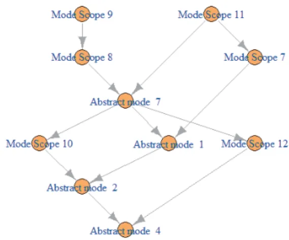
The structure of modes is generated thanks to a script. The result of its application on the case study is shown in Figure 3, using the modes of 6 scopes for visibility. As the modes imply each other, a
Figure 3: Implication structure of scope modes and abstract modes
path of implication correspond to preconditions that are more and more specific. Keeping only the longest paths, obtained by transitive reduction (which has been applied in the example), correspond to progressive definitions of increasing details in the preconditions that are each evaluated once.
6
METHOD
The system is modeled while considering separately its states and its behavior. The same approach is then applied on its elements, detailing the behavior while maintaining states and their traceabil-ity. The goal is to specify and check an integrated system and its behavior that would otherwise be either unspecified or emergent depending on the level of development. The method developed follows this process:
(1) Define types of states providing information on the system at its own level of granularity.
(2) Define simple and complex constraints between the values of different types of states to correlate the information. (3) Define enabling circumstances of the system use cases using
the system states.
(4) Check all states constraints and use cases preconditions. (5) Generate the structure of modes.
(6) Build the system description and behavior models. Once an integrated model of the system is obtained, more V&V activities can be performed, such as simulation. The model evolves by completing its elements models, their description (states), and the behavior detailed amongst all elements.
The information expressed by the states can evolve internally through deduction amongst types of states. They also can be modi-fied by the behavior or be communicated by the environment. The use cases, however, express interaction with the system processed through its behavior, and do not directly change the system state. This way, both the behavior and the actions on the system can evolve and be detailed without modifying the description of the system.
7
CONCLUSION AND PERSPECTIVES
Our results helped proving that our definition of system states enables to specify the system and its behavior, its evolution and the conditions under which use cases can be performed. The most direct benefit of this work is a means to check the preconditions of the use cases, not just individually but as part of a constrained whole. In the same way, it is important to early validate that all the anticipated use cases for an SoS are realistic and that no feature interactions will prevent the SoS to fulfill its missions. The simplic-ity of the solution makes it available to any engineer working on use case specification and can be easily integrated in an existing method, process or tool. One of the gains expressed by the BT engi-neers who experimented our approach was that preconditions were clearer but more importantly centralized, and instead of repeating similar information and preconditions in many requirements, those information are expressed by the same elements, the states.
The method presented does not guarantee to cover all states of the system, nor all details of its behavior. It simply aims at specifying the integration of the system to check its coherence and reduce emergence in its properties and behavior. The method remains to be deployed on a whole project for validation purposes. It also only covers discrete event phenomena.
The next step is to perform V&V activities on the model and then conduct the same analysis on a developed design using part of the model to check the continuity.
ACKNOWLEDGMENT
This work is supported by Bombardier Transport SAS and the ANRT CIFRE grant #2016/0262.
REFERENCES
[1] R. J. Abbott. 2007. Emergence and systems engineering: putting complex systems to work. In Symposium on Complex Systems Engineering, RAND Corporation, Santa Monica, CA. 11–12.
[2] Jean-Raymond Abrial. 2010. Modeling in Event-B: system and software engineering. Cambridge University Press, Cambridge; New York. OCLC: 646068815. [3] R. Baduel, JM Bruel, I. Ober, and E. Doba. 2018. Definition of states and
modes as general concepts for system design and validation. (2018). https: //hal.archives-ouvertes.fr/hal-01989427
[4] R. Balakrishnan and K. Ranganathan. 2012. A Textbook of Graph Theory. Springer New York, New York, NY. https://doi.org/10.1007/978-1-4614-4529-6 [5] Paul Baracos. 1992. Grafcet step by step. Famic Automation, Incorporated. [6] Albert Benveniste, Benoît Caillaud, and Dejan et al. Nickovic. 2015. Contracts
for Systems Design: Theory. Research Report RR-8759. Inria Rennes Bretagne Atlantique ; INRIA. 86 pages. https://hal.inria.fr/hal-01178467
[7] Egon Börger and Robert Stärk. 2003. Abstract state machines: a method for high-level system design and analysis. Springer Science & Business Media. [8] Mohammad Chami, Philipp Oggier, Omar Naas, and Matthias Heinz. 2015. Real
World Application of MBSE at Bombardier Transportation. In The Swiss Systems Engineering Day (SWISSED 2015), Kongresshaus Zurich.
[9] Richard Fujimoto, Conrad Bock, Wei Chen, Ernest Page, and Jitesh H. Panchal. 2017. Research challenges in modeling and simulation for engineering complex systems. Springer.
[10] David Harel. 1987. Statecharts: A visual formalism for complex systems. Science of computer programming 8, 3 (1987), 231–274.
[11] Bill Haskins, Jonette Stecklein, Brandon Dick, Gregory Moroney, Randy Lovell, and James Dabney. 2004. 8.4.2 Error Cost Escalation Through the Project Life Cycle. INCOSE International Symposium 14 (06 2004), 1723–1737. https://doi. org/10.1002/j.2334-5837.2004.tb00608.x
[12] John Hopcroft, Rajeev Motwani, and Jeffrey Ullman. 2001. Introducrion to Au-tomata Theory, Languages and Computation. Addison-Wesley.
[13] Jesko G. Lamm and Tim Weilkiens. 2010. Functional Architectures in SysML. Proceedings of the Tag des Systems Engineering (TdSE 10). Munich, Germany (2010). [14] Jean-Louis Le Moigne. 1994. La théorie du système général: théorie de la
modélisa-tion. Presses Universitaires de France.
[15] Michel D. Ingham, Robert D. Rasmussen, Matthew B. Bennett, and Alex C. Mon-cada. 2005. Engineering Complex Embedded Systems with State Analysis and the Mission Data System. AIAA Journal of Aerospace Computing, Information, and Communication, Vol. 2.
[16] Luca Pazzi. 2014. Modeling Systemic Behavior by State-Based Holonic Mod-ular Units. In Model-Driven Engineering Languages and Systems, Juergen Din-gel, Wolfram Schulte, Isidro Ramos, Silvia Abrahão, and Emilio Insfran (Eds.). Vol. 8767. Springer International Publishing, Cham, 99–115. https://doi.org/10. 1007/978-3-319-11653-2_7
[17] Mathias Soeken and Rolf Drechsler. 2015. Formal Specification Level. Springer International Publishing, Cham. https://doi.org/10.1007/978-3-319-08699-6 [18] Thiago Rocha Silva. 2018. A behavior-driven approach for specifying and testing
user requirements in interactive systems. PhD Thesis. Université de Toulouse, Université Toulouse III-Paul Sabatier. http://thesesups.ups-tlse.fr/3940/