To link to this article: DOI:10.1016/j.ijrmhm.2014.09.018
http://dx.doi.org/10.1016/j.ijrmhm.2014.09.018
This is an author-deposited version published in:
http://oatao.univ-toulouse.fr/
Eprints ID: 12007
To cite this version:
Yahiaoui, Malik and Paris, Jean-Yves and Denape, Jean and Dourfaye,
Alfazazi Wear mechanisms of WC–Co drill bit inserts against alumina
counterface under dry friction: Part 1 — WC–Co inserts with homogenous
binder phase content. (2015) International Journal of Refractory Metals
and Hard Materials, vol. 48. pp. 245-256. ISSN 0263-4368
O
pen
A
rchive
T
oulouse
A
rchive
O
uverte (
OATAO
)
OATAO is an open access repository that collects the work of Toulouse researchers and
makes it freely available over the web where possible.
Any correspondence concerning this service should be sent to the repository
administrator:
[email protected]
Wear mechanisms of WC–Co drill bit inserts against alumina counterface
under dry friction: Part 1 — WC–Co inserts with homogenous binder
phase content
M. Yahiaoui
a,⁎
, J.-Y. Paris
a, J. Denape
a, A. Dourfaye
baUniversité de Toulouse, Laboratoire Génie de Production, France bVarel Europe, France
a b s t r a c t
Keywords: Roller cone bit Cemented carbide Acoustic emission Contact temperature Wear mechanisms Third body
The tribological behavior of commercial roller cone bit inserts was studied by using a rotary tribometer and abra-sive alumina counterfaces. Three cemented carbide WC–Co inserts were selected with different cobalt content and WC grain size distribution. During tests, a nominal load was set at 264 N, the velocity at 0.5 m ⋅ s−1and the test time at 1 h. The experimental measurements were performed using load, torque, displacement sensors, an acoustic emission sensor and four thermocouples. These measurements showed that the friction coefficient and the mean contact temperature decrease with the cemented carbide's cobalt content. The acoustic emission energy displayed a clear dependence with the mean WC grain size and the WC–Co fracture toughness. It was also found that the insert's wear is proportional to the load but not to the time (or distance). Eventually, a third body approach clearly showed that the inserts and the counterfaces contribute to form an interfacial abra-sive paste. The stability, the composition and the cohesion of this paste govern the tribological behavior of the WC–Co/alumina contact.
1. Introduction
Two kinds of tools are mainly employed in the drilling industry: roll-er cone and drag bits. Rollroll-er cone bits work by impact excavation while drag bits operate by shear mode cutting in soft rock to medium hard for-mations. Drag bits are more and more used and studied because of their
greater excavation efficiency[1]. Nevertheless, roller cone bits are still
used in the hardest rock formations because of their better impact resistance.
Several cemented carbide WC–Co inserts, mounted on rotating cones, compose the roller cone bits (e.g. 109 inserts on Varel's 22 mm diameter bit HE23DMRSV). With the impact interaction, the other aspect of rotary drilling is the friction generated on the inserts. Hence, improving the im-pact resistance of conventional inserts leads inevitably to a decrease in their abrasive resistance. This is called the compromise between hardness and fracture toughness of cemented carbides.
Through this compromise, manufacturers modulate the carbide grain size and the cobalt content to act on the impact resistance and the wear resistance. Actually, coarse WC grain size distribution is rather
used to obtain high impact resistant inserts but affects the wear resis-tance. A high ductile binder phase content also enhances the impact resistance but decreases the wear resistance.
Chermant and Osterstock[2]first explained that the wear
mecha-nism of WC–Co is mainly produced by breakage in the Co ductile phase. However, they add that when the cobalt content of cemented carbides is relatively low, the contiguity of WC aggregates causes other breakage modes:
• Fractures of carbide grains (W/C);
• Fractures following the interface of agglomerate carbide grains (WC/ WC);
• Fractures following the interface carbide–cobalt (WC/Co); • Fractures in the cobalt phase (Co/Co).
In this way, for the cemented carbides from 3 to 20 wt. % of cobalt content, Chermant and Osterstock described that the fracture toughness depends on the cobalt content. For the highest cobalt content, inter-granular cracks at the interface WC/Co and in the binder phase Co/Co become the prevailing mechanism. Inversely, for the lowest cobalt con-tent, the part of intergranular cracks at the interface between carbide grains WC/WC increases.
Later, Beste et al.[3]proposed a review of WC–Co insert bits wear
mechanisms in real drilling conditions. They describe a succession of mechanisms including depletion of cobalt by rock's abrasive particles,
⁎ Corresponding author at: Ecole Nationale d'Ingénieurs de Tarbes, Adress: 47 avenue d'Azereix 65016 Tarbes, France.
WC grain fractures and finally grain fragment losses. More precisely,
Gee et al.[4]found that fracture and fragmentation of WC grains results
from the accumulation of plastic deformations in these grains preceded by plastic deformations in the binder phase.
This study focuses on the analysis of conventional WC–Co insert wear mechanisms. Wear experiments were carried out on a rotary tribometer in dry friction against alumina disc counterfaces. Physico-chemical and mechanical properties were considered to establish rela-tionships between wear behavior and microstructural characteristics. A third body approach was considered for a more complete description of the whole wear mechanisms through the concept of tribological circuit.
2. Material properties 2.1. Manufacturing process
Three different commercial inserts with various WC grain sizes and cobalt contents were selected for this study. These WC–Co inserts are referenced as P8, P12 and P16 and are respectively associated to a manufacturing process using 8 wt. %, 12 wt. % and 16 wt. % of cobalt powder.
These inserts were then sintered under isostatic pressure at 1365 °C from a mixed powder of WC and Co. The formed cemented carbide has a binder phase mainly composed of face-centered cubic Co. The inserts are eventually tumbled in a jar permitting multiple collisions between them (High Energy Tumbling process developed by Varel Internation-al). This last stage enhances the residual stresses distribution near the active area by reducing the tensile stresses formed after sintering. Final-ly, the studied inserts have a spherical active area with a radius of 4.37 mm.
2.2. Microstructural characterization
The inserts microstructure reveals trapezoidal WC grains
sur-rounded by a Co binder phase (Fig. 1). The P8 insert has clearly the finest
granulometry (Fig. 1). The P12 insert microstructure displays coarse WC
grains (Fig. 1). The P16 insert display an intermediate granulometry
be-tween the P8 insert and the P12 insert (Fig. 1).
2.3. Physicochemical and mechanical properties
The cobalt content pCoof each insert was evaluated by EDX
analyzes (Jeol JSM-7000F SEM associated with Bruker XFlash 4010 detector) on a polished section near the active surface. The EDX de-tector was calibrated with copper before each observation campaign to perform semi-quantitative measurements. The SEM was adjusted at 15 kV with a working distance of 15 mm. The electron beam intensity was set around 100 counts per second to enable a high speed analysis. The cobalt mass content distribution was evaluated with a step of 500 µm along five lines of 2.5 mm length on the sections. As expected, the P8 and P12 inserts have a cobalt content
of 8 ± 1 wt. % and 12 ± 2 wt. % (Table 1). For the P16 insert,
the measured cobalt content is only 15 ± 1 wt. % near the active surface.
The inserts mean grain size was measured by a screening image analysis. The P8 and P16 inserts have a monomodal grain size dis-tribution with mean grain sizes of respectively 2.8 ± 0.7 µm and 5.0 ± 1.3 µm. The P12 insert has a bimodal grain size distribution with a mean grain size of 7 ± 3 µm. For this insert, the two populations of grains are centered at 3.6 ± 0.4 µm and 5.6 ± 0.5 µm.
The density, measured with a liquid pycnometer, logically decreases with the cobalt content. The Young modulus and the Poisson coefficient were evaluated by ultrasonic wave propagation using a couple of transducers. The longitudinal and transverse acoustic velocities were then measured to calculate the elastic
modulus (Eq. (1)). The results are similar to the literature [5],
even if the used formula is only suitable for homogeneous and isotropic materials. The insert's Young modulus significantly
decreases with the cobalt content and the Poisson coefficient re-mains constant at about 0.2.
E ¼ 2ρ v2L−v 2 T ! 1 þ ν ð Þ 1−2νð Þ ν¼ v 2 L 2v2 T −1 ! v2L v2 T −1 !−1 8 > > < > > : : ð1Þ
The hardness was determined by Vickers indentations at a load of 2 kg for 10 s (Zwick/Roell ZHU 2.5 device) near the active surface. As expected, the hardness decreases with the cobalt content and the insert's ductility. As the manufacturers well know, the hardness also de-creases with the WC grain size. This explains the close hardness be-tween the P12 and P16 inserts.
The fracture toughness KICwas also evaluated by Vickers
indenta-tions under a load of 150 kg for 10 s to generate cracks on the insert's polished sections. Cemented carbides develop Palmqvist type cracks
[6]. The equation used to determine the fracture toughness depends
on the crack's mean size c, the Young modulus E, the hardness H, the
maximum indentation force Fmand a dimensionless factor δ depending
on the device characteristics (Eq.(2))[7]. This factor δ was evaluated at
0.084 ± 0.009 using a standard alumina sample with a fracture
tough-ness measured in previous studies at 5 ± 0.1 MPa ⋅ m12[8]. The fracture
toughness values obtained here are consistent with the values exposed
in the literature[9]. KIC¼ δ E H ( )12F m c32 ð2Þ
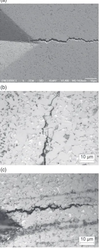
The energy dissipated by the crack propagation in the binder phase Co/Co is higher than the one spent at the interface WC/WC. This ex-plains the dependence of the fracture toughness with the cobalt con-tent. Actually, the P12 insert has the highest fracture toughness and proves that this result is also influenced by the WC grain size. The coarse WC grains favor transgranular crack propagation W/C, as it was
ob-served after Vickers indentations (Fig. 2). The transgranular crack
mech-anism dissipates the greatest amount of energy during degradations of cemented carbides. Consequently, the average cobalt content and the relatively coarse microstructure of the P12 insert both explain its high toughness.
3. Experimental device 3.1. Rotary tribometer
The experimental device is a rotary tribometer where a lever arm
applies the normal load to a sphere/plane configuration (Fig. 3). The
static WC–Co insert slides against a rotating alumina counterface at a
nominal velocity of 0.5 m ⋅ s− 1and a nominal load of 264 N for 1 h.
These parameters were selected after several campaigns at progressive
loads (0 to 300 N) and velocities (0.1 to 1 m ⋅ s−1). The aims were to
obtain significant wear volumes with the studied inserts and to avoid instabilities in the contact at extreme loads or velocities. Torque sensors measured the transverse friction force and a vertical displacement sen-sor provided changes in wear volume during the tests. Each experiment was repeated twice. In addition, three other loads were set at 14 N, 114 N, 189 N with the same nominal velocity and test time. The
contact was initiated after a time of 120 s in order to synchronize all the acquiring devices.
An acoustic emission device was also used to acquire acoustic signals produced by the sliding contact. An acoustic emission sensor was coupled on the upper shaft at 120 mm from the fixed insert to obtain intense signals and, at the same time, to avoid signal saturation. This sensor is a large band type (reference Micro-80 from Euro Physical Acoustic) operating at its maximum sensitivity between 100 kHz and 1 MHz. Before each experiment, the coupling of the sensor was con-trolled by the Hsu–Nielsen source method described by the standard NF EN 1330 ‐ 9. Four thermocouples were also placed on the upper shaft at 20 mm, 67 mm, 130 mm and 175 mm from the contact, re-spectively associated to four temperature measurements T20, T67, T130 and T175.
3.2. Alumina counterface
The counterfaces are alumina disks of 55 mm in diameter and 10 mm thick. The insert/disk contact is performed on a circle trajectory 36 mm in diameter.
The alumina is a corundum variety (α ‐ Al2O3), pure at 99.7%, con-taining 0.3% of MgO. Its physical and mechanical properties are gathered inTable 2. The alumina mean grain size of 8.5 ± 6.5 µm reflects a bi-modal distribution centered at 2 µm and 15 µm.
The choice of this alumina was motivated by its good mechanical properties and its chemical inertness. The mechanical strength of alumi-na is high compared to alumi-natural rocks. Furthermore, alumialumi-na is often used in abrasive application (e.g. polishing products) because of its high hardness. Alumina was then considered to obtain significant wear on cemented carbides in a relatively short test time.
3.3. Signal processing
For all the experiments at constant load, the friction coefficient reached a permanent regime after a few seconds. The evolution of the friction coefficient μ was treated by a moving average (i.e. root mean
square operation) (Fig. 4).
The emission acoustic signals were sampled considering the
param-eters defined inTable 3. The absolute acoustic energy Eawas extracted
by integrating the signal over time. This parameter was used to follow changes in the sliding contact behavior. It completes the mechanical in-formation given by the friction coefficient.
The mean contact temperature T0during the experiments was
evaluated through the four thermocouples measurements T20, T67,
T130and T175. These values were used to calculate the thermal
diffu-sivity Dtharound the contact. Afterwards, the mean contact
temper-ature T0was determined as a solution of the heat equation in the
Dirichlet conditions (Eq.(3)). T(x, t) is the temperature of the
con-sidered thermocouple at the position x and the time t. Tarepresents
the room temperature.
T x;ð tÞ ¼ Taþ Tð 0−TaÞ # erfc x 2 ffiffiffiffiffiffiffiffiffiffiffiffiffi Dth# t p ! ð3Þ
The vertical displacement sensor measured the depth wear h of the
insert. From this parameter, the wear volume Vhwas calculated with
Table 1
Physicochemical and mechanical properties of the P8, P12 and P16 inserts (with the cobalt content pCo, the WC mean grain size ØWC, the density ρ, the Young modulus E, the Poisson ratio ν,
the hardness H and the fracture toughness KIC).
Inserts pCo (wt. %) ØWC (µm) ρ (g ⋅ cm−3) E (GPa) ν H (HV 2 kg/10 s) KIC (MPa ⋅ m12 ) P8 8 ± 1 2.8 ± 0.7 15.03 ± 0.05 594 ± 10 0.19 ± 0.02 1326 ± 31 11.0 ± 0.4 P12 12 ± 2 7.0 ± 3.0 14.43 ± 0.05 546 ± 10 0.19 ± 0.02 1095 ± 29 19.5 ± 0.8 P16 15 ± 1 5.0 ± 1.3 14.06 ± 0.05 502 ± 10 0.22 ± 0.02 1061 ± 3 18.2 ± 0.2
respect to the spherical cap volume equation (Eq.(4)). In this equation, R is the radius of the insert spherical tip.
Vh¼ π 3h 2 3R−h ð Þ ð4Þ
This calculus considers that the vertical depth wear of the alumina counterface is negligible. Actually, for all the experiments of this study, the final depth wear of alumina represented less than 10% of the final depth wear of the insert.
4. Thermomechanical results 4.1. Friction coefficient
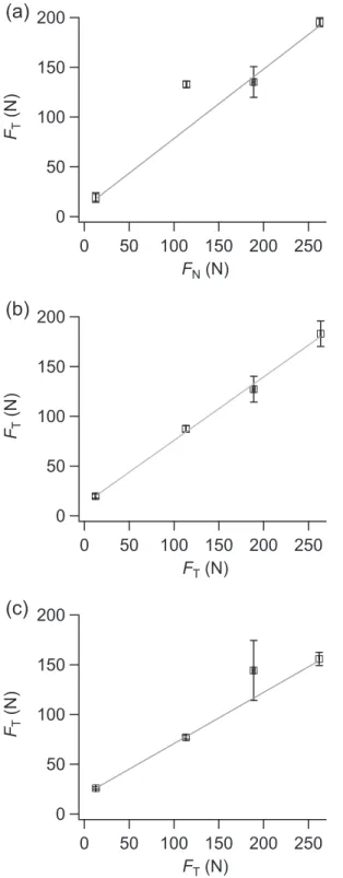
The friction forces verify an Amontons–Coulomb's law (Fig. 5). The
P8, P12 and P16 insert friction coefficients are respectively 0.70 ± 0.03, 0.64 ± 0.03 and 0.52 ± 0.02. Therefore, the friction coefficient de-creases with the insert's cobalt content. This observation was also con-firmed by the repeated tests at 264 N.
4.2. Contact temperature
The mean contact temperature T0has a sigmoidal tendency. The
mean contact temperature T0decreases with cobalt content and
in-creases with load (Fig. 6). At the beginning of the contact, the
tem-perature T0quasi-instantaneously rises from the room temperature
of 23 ± 3 ° C to 35 ± 3 ° C. Afterwards, for all the experiments, the contact temperature slightly increases until a jump on the signal be-tween 600 s and 1100 s. Then, an increase of temperature is record-ed with a tendency towards a maximum temperature (e.g. 155 ± 2 ° C at 264 N).
The temperature jumps occur later for higher cobalt contents (Fig. 6). The insert's Young modulus and hardness decrease with the cobalt content can explain this observation. With higher me-chanical properties, a greater hertzian contact pressure is realized and a process of contact conformity is produced sooner. Likewise, with a higher load applied on the insert, the jump also appears soon-er (Fig. 6).
The other contact temperature changes mainly depend on parame-ters defined by Fourier's law. The temperature changes ΔT is related to the thermal flow ϕ generated through a contact surface S and over a
thickness e of WC–Co with a thermal conductivity λ (Eq.(5)). The
tem-perature changes can also be expressed as a part of the energy produced
Fig. 2. Observations of crack propagations in cemented carbides after a Vickers indentation at 150 kg for 10 s: a — SEM observation of an intergranular crack propagation in the P8 insert; b — optical observation of an intergranular and a transgranular crack propagation in the P12 insert; c — optical observation of an intergranular crack propagation in the P16 insert.
WC-Co insert
with spherical tip
Plane alumina
counterface
by the sliding contact (i.e. FTv = μFNv) with κ the partition coefficient. ϕ¼ e λS ΔT ΔT ¼ e λS κ μ FNv 8 < : ð5Þ
All along the experiments, the average contact temperature ence between the P8 and P16 inserts is about 20%. Actually, the differ-ence of friction coefficient between these inserts is about 26%. The friction is clearly the most influential factor of contact temperature changes. Indeed, the P8 and P16 inserts thermal conductivity can
respec-tively be estimated at 86 W ⋅ m−1
⋅ K−1and 87.5 W ⋅ m−1⋅ K−1by a
law of mixtures. The thermal conductivity difference is then only about
2%. In addition, the ratio between the worn height h (with h = e0− e
and e0the initial thickness of heated WC–Co) and the final worn surface
of the P8 and P16 inserts in nominal conditions are respectively 44 ±
3 m−1and 47 ± 12 m−1. The evolution of the contact geometry only
represents a difference of 7% between the P8 and P16 inserts. Finally, the increase of cobalt content indirectly provokes a contact temperature drop by significantly reducing friction in the contact zone.
4.3. Acoustic emission
The absolute energy Earapidly reaches a maximum value at the
be-ginning and exponentially decreases in the rest of experiments (Fig. 7).
The mean absolute energy Eais the highest for the P12 insert and the
lowest for the P8 insert (Fig. 7). This observation could be juxtaposed
to the WC mean grain size measured for these inserts. Baranov et al.
[10]expressed that a coarse microstructure is a factor of acoustic
emis-sion amplification during sliding friction. However, they also related
that a greater hardness should produce more intense signals which is not the case here. Actually, the fracture toughness gathers the influence of the WC mean grain size and the hardness. The fracture toughness is also related to acoustic emission because crack propagations are sources of these mechanical waves. Therefore, the energy spent in the crack for-mation is partially reflected in the acoustic absolute energy. In this case, a high fracture toughness must be associated to the generation of highly energetic acoustic wave in the contact.
4.4. Wear kinetic
After the tests at constant load, the final worn volumes of WC–Co
in-serts Vfand alumina counterfaces Wfare clearly proportional to the
applied load (Fig. 8). Therefore, the total worn volume of the contact
insert/alumina (i.e. Vf+ Wf) is proportional to the load.
The wear rates of the inserts kv were calculated through the
Archard's model considering the product of the load FNby the sliding
distance L. These wear rates increase logically with the cobalt content
and the ductility of the cemented carbides (Table 4). Otherwise, the
wear rate of the alumina counterface kwis maximum against the P12
insert and minimum against the P16. For the P8 and P12 inserts, the alu-mina wear rate represents about three times the wear rates of the in-serts. Conversely, the alumina counterface associated with the P16 insert has a lower wear rate than the cemented carbide.
The experiments in nominal conditions show that the insert's wear does not really follow an Archard model along the sliding duration of
the tests (Fig. 9). The evolution of the wear volume Vhis not exactly
pro-portional to the time t (i.e. distance L).
The wear volume curves can approximately be described by two
lin-ear stages with a transition around a product FNL of 1.5 ⋅ 105
N ⋅ m (i.e.
1300 s). These linear stages can be associated to two wear rates k1and
k2with respect to the Archard model (Table 5). The regime transition is
followed by a significant wear deceleration for the P12 insert, a slighter deceleration for the P16 and a wear acceleration for the P8 insert.
5. Post-experimental characterizations 5.1. Inserts worn surfaces
All the insert's worn surface have visible abrasion scratches in the
sliding direction (Fig. 10). Because of the conformity realized during
the experiments with the countermaterial, these worn surfaces have a slight curvature in the transverse sliding direction.
These surfaces also display material transfers spread along the slid-ing direction. The SEM observations reveal paste-like transfers. EDX analyses show that these transfers are formed by agglomerated alumina debris with WC grain fragments bound with the ductile cobalt phase (Fig. 11). The abrasive alumina particles in the contact interface influ-ence the insert's wear mechanism. The P12 insert material transfer
has the greatest alumina particle content (Fig. 11). The P16 insert
trans-fer has the lowest alumina content.
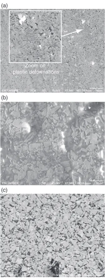
Under the material transfers, the insert's worn surface exhibits dif-ferent microstructural damages. After experiments, at the lowest load of 14 N, the insert's worn surface has a polished aspect revealing the
cemented carbide microstructure (Fig. 12). The P8 and P16 inserts
dis-play worn surface characteristics of a predominant intergranular crack propagation mechanism. Otherwise, the P12 insert shows a great amount of broken WC grains characteristic of a transgranular
Table 2
Physical and mechanical properties of the alumina counterface (with the porosity po, the alumina mean grain size ØAl2O3and the roughness Ra).
ρ (g ⋅ cm−3) po (%) ØAl2O3 (µm) Ra (µm) H (HV 2 kg/10 s) E (GPa) ν KIC (MPa ⋅ m12 ) [3.92] ± 0, 05 1.5 8.5 ± 6.5 0.12 ± 0.06 1260 ± 37 363 ± 10 0.22 5 ± 0.1 ewline
Fig. 4. Friction coefficient signal processing: acquired signal and moving average.
Table 3
Acquisition parameters of acoustic emission signals (The acronym PDT defines the peak definition time, HDT is the hit definition time and HLT is the hit lockout time).
Threshold Preamplification Sample rate
Pre-trigger PDT HDT HLT
dB dB kHz LGRms LGRms LGRms LGRms
mechanism. The coarse grains of the P12 bimodal distribution are clear-ly fragmented on the SEM micrograph. The P16 insert also has pulver-ized grains and clear voids subsequent to WC grains and cobalt extractions. More discretely, the P8 insert worn surface displays grain
plastic deformation. As described by Luyckx[11], low cobalt content
WC–Co such as the P8 insert does not permit to dissipate the overall en-ergy brought by the contact dynamic. Therefore, the contiguous WC grains are deformed.
Transgranular cracks can be revealed on cleaned worn surfaces of
the P16 insert and more discretely for the P8 insert (Fig. 13). As seen
after Vickers indentations, these observations confirm that the WC
200
150
100
50
0
F
T(N)
250
200
150
100
50
0
F
N(N)
200
150
100
50
0
F
T(N)
250
200
150
100
50
0
F
T(N)
200
150
100
50
0
F
T(N)
250
200
150
100
50
0
F
T(N)
(a)
(b)
(c)
Fig. 5. Friction coefficient calculated after tests at constant loads by an Amontons–Coulomb's law: a — P8; b — P12; c — P16.
160
120
80
40
T
0(°C)
3000
2000
1000
t (s)
P8
P12
P16
jumps
160
120
80
40
T
0(°C)
3000
2000
1000
t (s)
P8
P16
P12
(a)
(b)
Fig. 6. Mean contact temperature during the tests at constant load: a — inserts P8, P12 and P16 at a load of 264 N; b — inserts P8, P12 and P16 at a load of 189 N.
200
150
100
50
0
E
a(x10
9aJ)
2500
2000
1500
1000
500
t (s)
P12
P16
P8
810
10 2 4 6 810
11E
a(aJ)
P8
P12
P16
(a)
(b)
Fig. 7. Absolute energy of acoustic emission signals measured during nominal experi-ments: a — evolution of the absolute energy Ea; b — mean absolute energy Eacalculated
grain size distribution determine the preponderance of the transgranular crack propagation compared to the intergranular crack propagation.
According to the wear by extraction and fragmentation of grains, the worn surface roughness depends on the insert's WC grain size. Whatev-er the applied load used for the expWhatev-eriment, the worn surface roughness
is the highest for the P12 insert and the lowest for the P16 insert (Fig. 14). For example, for the tests performed and repeated at the load of 264 N, the worn surface of the P8, P12 and P16 inserts have re-spectively a roughness of 0.53 ± 0.02 µm, 0.94 ± 0.02 µm and 0.70 ± 0.03 µm.
5.2. Alumina counterfaces worn surfaces
The alumina counterfaces display grayish tracks as large as the in-serts worn surface. These dark tracks indicate that a great amount of material is transferred from the insert to the alumina. These tracks were observed by backscattered electron topographic mode after tests
at the lowest load of 14 N (Fig. 15). These observations display voids
formed by alumina grain pull-outs. At the microscopic level, the studied alumina degradation should be mainly governed by intergranular crack
propagations[12].
The superposition of the transverse profiles of the counterfaces wear track with the associated inserts worn surface reveals a clear geometric
conformity. This conformity is macroscopic and microscopic (Fig. 16).
The wear curvatures of the material couple are similar. The profiles
formed by the abrasive scratches on the material pair overlap.
5.3. Ejected debris
The ejected debris are composed of rather large flat tablets
surrounded by small isolated particles (Fig. 17). On one side, these
large tablets present a relatively smooth surface with shallow abrasion scratches. This smooth surface corresponds to the actual sliding inter-face. On the other side, the large tablets are formed by alumina grains. These grains were pulled out from the alumina countermaterial subsur-face. The ejected debris are the result of crack propagation by shearing actions in the tribofilm. They are mainly composed from alumina grains and insert elements.
100
80
60
40
20
0
Wear volume (mm
3)
400x10
3300
200
100
0
250
200
150
100
50
F
N(N)
F
N· L (N · m)
W f V f100
80
60
40
20
0
Wear volume (mm
3)
400x10
3300
200
100
0
250
200
150
100
50
F
N(N)
W f V fF
N· L (N · m)
100
80
60
40
20
0
Wear volume (mm
3)
400x10
3300
200
100
0
250
200
150
100
50
F
N(N)
W f V fF
N· L (N · m)
(a)
(b)
(c)
Fig. 8. Inserts final worn volume Vfand the associated alumina counterfaces final
worn volume Wfafter tests at constant loads considering the Archard's model: a — P8;
b — P12; c — P16.
Table 4
P8, P12 and P16 inserts wear rates kvand associated alumina counterface wear rates kw
after test at constant load. Wear rates (10−5mm3 ⋅ N−1⋅ m−1) P8 P12 P16 kv 5.0 ± 0.3 5.7 ± 0.4 8.2 ± 0.8 kw 15.2 ± 1.6 17.6 ± 0.4 6.0 ± 1.2
40
30
20
10
0
V
h400x10
3300
200
100
0
F
N· L (N ·m)
3000
2000
1000
t (s)
P8
P12
P16
Fig. 9. Wear volume Vhchange during experiments in nominal conditions (i.e. load of
6. Discussions 6.1. Third body approach
The wear dynamic can be better described by considering a third body approach. In this approach, the tribological cycle deals with the
different matter flow inside an outside the contact (Fig. 18). Four main
matterflows operate in this case[13]:
• The particles detachment from WC–Co and alumina (first bodies) generates the source flow Qs;
• The third body circulation in the contact forms the internal flow Qi. The internal flow leads the debris (third body) to accommodate the velocity gradient in the contact;
• A part of the particles leaving the interface comes back in the sliding contact defining the recycling flow Qr;
• The wear flow Qwis created when particles from the third body
defin-itively leaves the contact.
Surface damage begins by alumina grain pull-outs as a result of a
critical contact pressure and intergranular crack propagation (Fig. 19).
Then, these free abrasive alumina particles remove preferentially the ductile cobalt phase from the inserts. This binder depletion leads to the decohesion and the extraction of WC grain fragments. Alumina par-ticles, cobalt phase and WC fragments form the source flow Qs.
The third body generated at the interface becomes a cohesive paste separating the contacting surfaces. This tribofilm constitutes the inter-nal flow Qi.
As a consequence of the alumina particle's contribution, the third
body acts as an abrasive paste (Fig. 20). The tribofilm is highly sheared
in the contact, flows outside the sliding zone and breaks. A part of the debris stays on the counterface track and returns into the contact.
These particles constitute the recycle flow Qrwhich feed again the
internal flow Qi. The debris definitively ejected from the contact repre-sent the wear flow Qw.
6.2. Inserts properties and wear
The inserts (and the alumina counterface) bulk properties influence the wear mechanisms by feeding the third body through the source flow Qs. Naturally, increasing the cobalt content and the ductility of the cemented carbide increases the insert's wear. A coarse WC–Co mi-crostructure acts on the fracture toughness by favoring a transgranular cracking mode in the insert during friction. The high energy dissipation induced by the transgranular crack propagation during friction en-hances the insert's wear resistance.
Table 5
Linear first and second stages wear rates k1and k2for the P8, P12 and P16 inserts after
experiments in nominal conditions. Wear rates (± 0.5 × 10⁻⁵mm3 ⋅ N−1⋅ m−1) P8 P12 P16 k1 3.4 9.4 10.7 k2 6.8 2.2 7.5
Fig. 10. SEM observation of the P16 worn surface (the arrows indicate the sliding direction).
14
12
10
8
6
4
Al content (wt.%)
P8
P12
P16
(a)
(b)
Fig. 11. SEM observations and EDX characterizations of the insert's worn surface after an experiment at constant load of 264 N: a — P16 worn surface magnified view and the as-sociated element map (tungsten elements are in green, the cobalt elements are in blue and the aluminum elements are in pink); b — Aluminum element semi-quantification on the worn surface by EDX (with repeatability tests). (For interpretation of the references to color in this figure legend, the reader is referred to the web version of this article.)
Considering the whole tribological circuit, several cases can be
ob-served depending on the cobalt content and the WC grain size (Fig. 21):
• A low cobalt content (e.g. P8 insert), i.e. a high hardness, favors to the counterface wear and the alumina particle introduction in the source
flow Qs(case I). However, a little amount of cobalt is introduced in the
contact. Accordingly, the third body is not cohesive and the abrasive particles are not stabilized at the interface (i.e. powdery-like third body);
• A high cobalt content (e.g. P16 insert) induces poor alumina particle introduction in the source flow Qs. However, these particles are stabi-lized in an abrasive paste at the interface (case II). This third body is
Fig. 12. SEM observations of the inserts worn surfaces after experiments at constant loads of 14 N (images size of 80 µm × 64 µm): a — P8; b — P12; c — P16.
Fig. 13. SEM observations by backscattered electron analysis of cleaned worn surfaces: a — P8; b — P16.
1.0
0.8
0.6
0.4
0.2
0.0
R
a(µm)
250
200
150
100
50
0
F
N(N)
P8 P12 P16Fig. 14. Roughness of the P8, P12 and P16 inserts after experiments at constant loads: pro-file arithmetic average Ravs. normal load FN.
then harmful and favors the insert wear. The formation of this paste is also coherent with the friction coefficient decreasing with the inserts cobalt content (i.e. the third body shearing action is expected to be easier);
• With coarse WC grains (e.g. P12 insert), in the short term, great vol-umes of grains are removed from the insert (case III, stage 1). In the
longer term, a rough worn surface is formed and a great amount of particles are trapped in the contact (case III, stage 1). Eventually, this trapping may realize an hardening of the insert active surface. Then, the cemented carbide participation may be reduce in the source flow Qs.
7. Conclusion
The tribological behavior of three commercial WC–Co inserts refer-enced P8, P12 and P16 was studied here. These inserts are associated to different homogeneous cobalt phases of respectively 8 ± 1 wt. %, 12 ± 2 wt. % and 15 ± 1 wt. %. They also have different WC average grain size distributions of respectively 3 ± 1 µm, 7 ± 3 µm and 5 ± 1 µm.
To perform significant wear on the inserts, the experimental cam-paign considered a nominal load of 264 N and a sliding velocity of
0.5 m ⋅ s−1during a test time of 1 h. Moreover, alumina was selected
as countermaterial because of its abrasive characteristic. The results showed that:
• The friction coefficient mainly decreases with the cobalt content. The studied WC grain size variations do not change this trend;
• The mean contact temperature decreases with the cobalt content; • The acoustic emission signal energy increases with the WC grain size.
This must be related to the insert's fracture toughness and the energy dissipation in the contact (competition between intergranular and transgranular crack propagation modes).
Fig. 15. SEM observation of the counterface wear track associated to a P12 insert at the constant load of 14 N using the topographical imaging mode.
-60
-40
-20
0
Profile (µm)
6
4
2
0
Transverse position
to the sliding direction (mm)
Insert
Counterface
Microscopic
confomity
Fig. 16. Transverse profile of the counterface wear track superpose to the transverse pro-file of the associated P16 insert worn surface.
Fig. 17. SEM image coupled with an EDX analysis of ejected debris (tungsten elements are in green, the cobalt elements are in blue and the aluminum elements are in pink). (For inter-pretation of the references to color in this figure legend, the reader is referred to the web version of this article.)
WC-Co
Third
body
Q
sQ
iQ
wQ
rAl O
2 3Fig. 18. Tribological circuit diagram with flows Qs, Qi, Qwand Qr(respectively source flow,
• The inserts wear is proportional to load and logically increases with the cobalt content. However, wear does not exactly follow an Archard model. The inserts wear volume can be describes by two tenden-cies at short term and long term (or short distance and long distance);
• An abrasive paste is formed at the interface. This paste is made of alumina and WC fragments embedded in the cobalt binder phase at the sliding interface.
An analysis on the basis of a third body approach shows that: • The cobalt content influences wear by modulating the hardness. It
con-trols the alumina abrasive particles and the ductile cobalt phase flows in the contact;
• A coarse WC–Co microstructure (e.g. insert P12) favors, in a short term, the pull-out of WC–Co material. At a longer term, the rough worn sur-face, formed by the pull-outs, traps alumina particles and produces a hardening of the insert's active surface. As a consequence, the source flow of the WC–Co is reduced;
• A fine WC–Co microstructure (e.g. insert P8) implies a low wear kinetic at the beginning of an experiment. At a longer term, the wear kinetic is accelerated by a great wear flow because of a poor trapping mecha-nisms. In such conditions, the source flow of WC–Co remains constant;
• The friction coefficient decreases with the cobalt content as a result of a lower third body shearing resistance. This friction forces reduction and also explains the dependence between the contact temperature and the cobalt content.
Finally, the P8 insert is the more wear resistant followed by the P12 then the P16. This result highlights the interest of innovating inserts
with graded cobalt distribution (see part 2[14]).
Acknowledgments
This study was developed during the thesis of the university of Tou-louse “Tribological behavior of polycrystalline diamonds and graded cemented carbides WC–Co — Application to drill bits inserts and cutters for the drilling of abrasives rock formations” supported by the program
ANR-09-MAPR-0009 of the Agence Nationale de la Recherche[15]. We
thank the Varel Europe company for the elaboration of commercial inserts used in this study.
References
[1] M. Yahiaoui, L. Gerbaud, J.-Y. Paris, J. Denape, A. Dourfaye, A study on PDC drill bits quality, Wear 298–299 (2013) 32–41.
WC-Co
Al
2O
3WC-Co
Al
2O
3Intergranular cracks
in the alumina counterface
Grains extraction and milling
Free abrasive
grain fragments of alumina
Removal of cobalt and
of WC fragments
Critical contact
pressure
Co
Fig. 19. Source flow Qsand third body formation in the contact between the insert WC–Co and the alumina counterface.
Abrasive paste formation
in the contact
Debris ejection
Shearing of the third body
and cracking in the alumina
Debris trapping
Source flow Q
sInternal flow Q
iWear flow Q
wAl
2O
3WC-Co
Al
2O
3WC-Co
Al
2O
3WC-Co
Fig. 20. General wear mechanism between the insert WC–Co and the alumina counterface modeled as source flow Qs, internal flow Qiand wear flow Qwgeneration in the contact (the
alumina particles are drawn in brown, the cobalt is in blue and the WC grains are in gray). (For interpretation of the references to color in this figure legend, the reader is referred to the web version of this article.)
[2] J.L. Chermant, F. Osterstock, Fracture toughness and fracture of WC–Co composites, J. Mater. Sci. 11 (1976) 1939–1951.
[3] U. Beste, T. Hartzell, H. Engqvist, N. Axén, Surface damage on cemented carbide rock-drill buttons, Wear 249 (2001) 324–329.
[4] M. Gee, A. Gant, B. Roebuck, Wear mechanisms in abrasion and erosion of WC/Co and related hardmetals, Wear 263 (2007) 137–148.
[5] F. Felten, G. Schneider, T. Sadowski, Estimation of R-curve in WC-Co cermet by CT test, Int. J. Refract. Met. Hard Mater. 26 (2008) 55–60.
[6] K. Jia, T. Fischer, B. Gallois, Microstructure, hardness and toughness of nanostruc-tured and conventional WC–Co composites, Nanostruct. Mater. 10 (5) (1998) 875–891.
[7] G. Anstis, P. Chantikul, B. Lawn, D. Marshall, A critical evaluation of indentation tech-niques for measuring fracture toughness, J. Am. Ceram. Soc. 64 (1981) 533–538.
[8] G. Ural, J.-Y. Paris, J. Denape, J.-D. Beguin, R. Merhej, J.G. Santanach, A. Webel, A. Peigney, C. Laurent, G. Chevallier, C. Estournes, Y. Paranthoen, Fretting behavior of alumina nanocomposites densified by SPS, ECOTRIB, vol. 1, 2009, pp. 213–218.
[9] Y. Torres, J.M. Tarrago, D. Coureaux, E. Tarrés, B. Roebuck, P. Chan, M. James, B. Liang, M. Tillman, R.K. Viswanadham, K.P. Mingard, A. Mestra, L. Llanes, Fracture and fatigue of rock bit cemented carbides: Mechanics and mechanisms of crack growth
resistance under monotonic and cyclic loading, Int. J. Refract. Met. Hard Mater. 45 (2014) 179–188.
[10] V. Baranov, E. Kudryavtsev, G. Sarycgev, V. Schavelin, Acoustic Emission in Friction, Elsevier, 2007.
[11] S. Luyckx, Slip system of tungsten carbide crystals at room temperature, Acta Metall. 18 (1970) 233–236.
[12]A.K. Mukhopadhyay, Y.-W. Mai, Grain size effect on abrasive wear mechanisms in alumina ceramics, Wear 162–164 (1993) 258–268.
[13] Y. Berthier, Maurice Godet's third body, in: D. Dowson, C. Taylor, T. Childs, G. Dalmaz, Y. Berthier, L. Flamand, J.-M. Georges, A. Lubrecht (Eds.), The Third Body Concept Interpretation of Tribological Phenomena, Tribology Series, vol. 31, Elsevier, 1996, pp. 21–30.
[14] M. Yahiaoui, J.-Y. Paris, J. Denape, C. Colin, O. Ther, A. Dourfaye, Wear mechanisms of WC–Co drill bit inserts against alumina counterface under dry friction — Part 2: Graded WC–Co inserts, Int. J. Refract. Met. Hard Mater. 48 (2015) 65–73.
[15] M. Yahiaoui, Comportement tribologique de diamants polycristallins et de carbures cémentés WC–Co avec traitements de graduation — application aux inserts et taillants d'outils pour le forage de formations rocheuses fortement abrasives, (Ph. D. thesis) Université de Toulouse, 2013.
WC-Co
WC-Co
Q
s
Q
s
Al
2
O
3
WC-Co
Case I
Case II
Case III, stage 1
Case III, stage 2
Q
s
Q
s
Al
2
O
3
WC-Co
Al
2
O
3
Al
2
O
3
Fig. 21. Influence of the cobalt content and the WC grain size of the inserts in the third body formation: insert with high cobalt content (I); insert with low cobalt content (II); insert with coarse WC grains (III, stages 1 and 2) (the alumina particles are drawn in brown, the cobalt is in blue and the WC grains are in gray). (For interpretation of the references to color in this figure legend, the reader is referred to the web version of this article.)