HAL Id: hal-00983458
https://hal.archives-ouvertes.fr/hal-00983458
Submitted on 25 Apr 2014
HAL is a multi-disciplinary open access archive for the deposit and dissemination of sci-entific research documents, whether they are pub-lished or not. The documents may come from teaching and research institutions in France or abroad, or from public or private research centers.
L’archive ouverte pluridisciplinaire HAL, est destinée au dépôt et à la diffusion de documents scientifiques de niveau recherche, publiés ou non, émanant des établissements d’enseignement et de recherche français ou étrangers, des laboratoires publics ou privés.
To cite this version:
Julien Sarrazin, Anne-Claire Lepage, Xavier Begaud. Circular High-Impedance Surfaces Character-ization. IEEE Antennas and Wireless Propagation Letters, Institute of Electrical and Electronics Engineers, 2012, 11, pp.260-263. �10.1109/LAWP.2012.2189349�. �hal-00983458�
Abstract—In this letter, characterization of circular
High-Impedance Surfaces (HIS) is investigated. The reflection phase characterization used for rectangular HIS is here extended to circular lattices. Circular HIS discussed in this letter present a 2D periodicity and consequently the phase diagram is determined for concentric and radial polarizations. The effect of mapping a rectangular HIS into a circular one is investigated in order to give some insights regarding the design of such metasurface. The presented characterization constitutes a useful tool for the design of low-profile antennas using HIS as reflector.
Index Terms— High-Impedance Surface (HIS), Artificial Magnetic Conductor (AMC), Electromagnetic Band-Gap (EBG) structures, metasurface, phase diagram characterization
I. INTRODUCTION
ince their introduction, High-Impedance Surfaces (HIS) [1] found themselves in a lot of applications. Most of them are based on two interesting properties that these metasurfaces exhibit. The first one is an Electromagnetic Band Gap (EBG) which forbids the propagation of surface waves. The second one is the in-phase reflection of incident waves, that makes the metasurface to behave like an Artificial Magnetic Conductor (AMC). These two properties have been extensively investigated in the field of microwave antennas leading to some improvements of their performances [2]. Though the most common structure used to perform a HIS is the array of square patches arranged in a two-dimensional lattice, many different patterns have been investigated [3]. Most of the time, only the shape of the single element is considered, the arrangement usually being a cartesian lattice. However, few papers deal with a circular arrangement of single elements [4, 5, 6]. In [4], the circular HIS presents a 1D-periodicity and is introduced as a Planar Circularly Symmetric EBG Structure (PCS-EBG). The EBG behavior of such a structure is studied and its benefit over a traditional rectangular lattice is highlighted for a printed antenna-based application. The aim being to suppress surface waves, using such geometry makes them experience the same band gap effect in all radial directions. Another antenna application is investigated in [5]. The 2D-periodicity circular HIS is used for the same purpose as in [4]: to suppress surface waves thanks to the EBG behavior. In addition to the higher flexibility on the antenna design over traditional cartesian configurations, it appears that circular configuration also improves the axial ratio of the
Manuscript received September 10, 2011.
The authors are with Institut Telecom; Telecom ParisTech; CNRS; LTCI; Paris, France (e-mail: [email protected]).
Digital Object Identifier:
circularly polarized circular patch antenna used in the study. A 1D-periodicity circular HIS is suggested in [6] to be used as an AMC for a low profile spiral antenna, but no design is given.
So it appears that circular lattices are considered to be used for HIS. However, the literature mainly focuses on the EBG behavior of such configurations whereas their AMC behavior has not been characterized. Cartesian lattice AMC’s response is usually obtained with the phase diagram method [7]. A single cell is simulated and by applying appropriate periodic boundary conditions, it is possible to determine the reflected phase of such a structure. The surface exhibits an AMC behavior when the reflected phase is null on the surface plane. By applying Floquet theorem, it is even possible to characterize the reflected phase for various incident angles [8]. However, when only the response for a normal incidence is desired and when the pattern does not introduce any cross-coupling between incident waves having orthogonal polarizations, the periodic boundary conditions of the unit cell can be replaced by Perfect Electric Conductor/Perfect Magnetic Conductor (PEC/PMC) conditions in order to generate a TEM wave [9, 10]. This unit cell characterization is well known and works well for cartesian lattices. In this paper, we propose to apply this characterization technique to circular lattices.
The circular HIS characterization is presented in section II. In section III, the influence of geometrical parameters is studied and some problems specific to the circular arrangement are discussed. The design methodology of a complete circular HIS is addressed in section IV and some useful guidelines are given. Finally, a conclusion is drawn in section V.
II. AMCCHARACTERIZATION
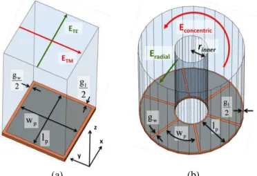
A circular HIS is the conformal mapping (using an exponential function) of the rectangular pattern shown in Fig. 1a into the cylindrical pattern shown in Fig. 1b. The rectangular (or square) patch is the well-known Sievenpiper pattern having or not a metallic via-hole in its center [1]. Since for normal incidence, the via-hole does not have any impact on the reflected phase, the structure in this paper will focus on patches which do not contain any vias. As it has been mentioned earlier, the AMC phase diagram for normal incidence is obtained by applying PEC and PMC boundaries on rectangular waveguide walls. For example, according to Fig. 1a, if a PEC condition is applied to the two walls lying in the yz plane and a PMC condition applied to the two walls in the xz plane, a TEM wave will be generated with an electric field oriented along x-axis (referred as ETE in Fig. 1a). If PEC
Circular High-Impedance Surfaces
Characterization
Julien Sarrazin, Member, IEEE, Anne-Claire Lepage and Xavier Begaud, Member, IEEE
along the y-axis (ETM). With this method, the phase diagram of
the HIS can be determined for both the polarizations shown in Fig. 1a. Similarly, the reflected phase of a circular HIS can be obtained. While mapping the cartesian geometry into the cylindrical one, the x-oriented polarization (ETE) becomes
ρ-oriented (Eradial) and the y-oriented polarization (ETM) becomes
φ–oriented (Econcentric) as shown in Fig. 1b. To generate TEM
waves with such polarizations in a cylindrical structure, the coaxial geometry is used as it can be seen in Fig. 1b. The coaxial waveguide ends on a circular HIS. Boundary conditions are applied to the inner and outer surfaces of the waveguide. To obtain a radial polarization (Eradial), PEC
conditions are applied to both the surfaces whereas to obtain a concentric polarization (Econcentric), PMC conditions are applied
to both the surfaces. Then the phase diagram is obtained with the same method than for cartesian HIS. Both the obtained polarizations may emulate the field radiated by a source (such as a linearly or a circularly, polarized antenna) located in the center of the circular HIS.
(a) (b)
Fig. 1 - HIS (a) unit cell of a cartesian lattice (b) unit ring of a circular lattice In cartesian structures, simulating a single cell is equivalent to assume an infinite HIS along x- as well as along y-directions. However, for circular HIS, though the structure is considered to be infinite along the radial dimension (along ρ-axis), it is finite along the angular dimension (along φ-axis). So while performing the mapping, a finite number of cells along φ-axis has to be chosen. Consequently, instead of a
unit-cell simulation, a unit-ring simulation is performed.
Furthermore, for a given inner radius rinner, the number of cells
will have an influence on the dimensions wp and gw (wp being
the patch width taken in the middle at lp/2 and gw is the gap
along the patch length lp). Intuitively, if the patch length lp and
the patch width wp remain unchanged between the cartesian
and the circular structure (as well as gw and gl), one could
expect that null reflected phase frequencies are conserved for both the polarizations. However, the curvature may have an impact on those frequencies. So, we firstly propose to study this influence.
On a FR4 epoxy substrate ( r=4.4, tan =0.02, h=1.58mm),
a square patch is firstly simulated with the following dimensions: wp=lp=26mm, gw=gl=1.5mm. Then, using the
same dimensions, a circular structure is designed and simulated. To keep the patch width wp and the gap gw
equal to:
, (1) with N the number of patches. Four different circular structures are studied, the varying parameter being the number of patches: N=6, 8, 12 and 16. The simulation has been performed with Ansoft HFSS using the methodology previously described to obtain the phase diagram. Results are shown in Fig. 2 for both the polarizations, except in the cartesian case for which only one polarization is given because the geometry is completely symmetric.
Fig. 2 - Phase diagram of cartesian and circular HIS
The cartesian pattern shows a null reflected phase at 2.47GHz. For circular lattices, radial and concentric modes do not exhibit the same null phase frequency. The radial mode exhibits a null phase frequency greater than the cartesian one whereas the concentric mode exhibits a lower one. Both these frequencies appear to be almost equally shifted from the cartesian pattern’s frequency. Differences regarding responses between cartesian and circular lattices can be explained by the curvature’s effect inherent to the circular structure. Moreover, when the number of patches N increases, the response becomes similar to the cartesian one. This is due to the fact that when the number of patches increases, the radius of the HIS increases as well, according to eq. 1, thereby making the curvature’s effect less strong. For N=16 patches, the radius of the circular HIS being quite large, the patches are not much bended so concentric and radial modes exhibit a null phase frequency very close to each other (2.45GHz and 2.48GHz respectively) and very close to the cartesian one too.
These results show that the curvature has an impact on the HIS response. So the characterization appears to be necessary: by simulating the circular HIS, it is possible to set the desired reflected phase response for both the polarizations. To design and to simulate the HIS in a cartesian lattice and then to map it into a circular one without any additional simulations can lead to some unexpected frequency shifts, especially when the radius of the HIS is small.
III. INFLUENCEOFTHEDESIGNDIMENSIONS The reflected phase response of a cartesian HIS depends on the size of patches and gaps [7]. While the patch length lp and
the gap gl have an impact only on the TE polarization response
(according to Fig. 1a), the patch width wp and the gap gw have
an impact only on the TM polarization response. However, since with a circular HIS an additional parameter exists (rinner),
sizes dependencies differ slightly from the cartesian ones. Indeed, if patch and gap sizes change, the curvature of the structure changes too. It has been shown previously that the curvature of the circular lattices has an effect on the response of both the polarizations. So by changing one dimension of the patch (or one gap), one can expect that both the radial and concentric null phase frequencies will be affected, thereby making the circular HIS design trickier than the cartesian HIS one. That is why the influence of the dimensions involved in the design is now investigated.
Fig. 3 shows the influence of the patch width wp on the
reflected phase for radial and concentric polarizations. The HIS has exactly the same properties than the one previously simulated with a number of patches N=6 (lp is constant and
equal to 26mm). The patch width has a direct impact on the concentric mode resonance as it has on the TM mode resonance for cartesian lattices (see Fig. 1a). So changing wp
achieves a significant frequency shift on the concentric mode phase response as it can be observed in Fig. 3. Like with cartesian HIS, the smaller the patch width, the greater the null phase frequency. Nevertheless, a modification of the patch width changes the radius of the HIS and so the curvature experienced by the radial mode. This explains why the radial polarization phase response is affected by slight frequency shifts as well.
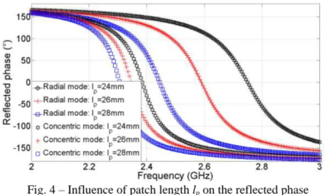
Fig. 3 – Influence of patch width wp on the reflected phase The influence of the patch length lp is shown in Fig. 4 (wp
being constant and equal to 26mm). The patch length has a direct influence on the radial polarization resonance. So a variation of lp changes significantly the radial mode phase
response as it can be observed in Fig. 4. The patch length having an impact on the HIS curvature, concentric mode phase response is also influenced but to a lesser extent.
Fig. 4 – Influence of patch length lp on the reflected phase Fig. 5 shows the influence of the gap gl along the radial
direction (with wp=lp=26mm and gw=1.5mm). A modification
of gl largely influences the radial mode phase response. Like
with cartesian HIS, the smaller the gap, the lower the null phase frequency. However, this gap being tangential to the concentric electric field, it does not have any effect on the concentric mode response.
Fig. 5 - Influence of the gap gl on the reflected phase
The influence of the gap gw along the angular dimension
can be seen in Fig. 6 (with wp=lp=26mm and gl=1.5mm). The
null reflected phase frequency of the concentric mode can be tuned by adjusting the value of gw. Like previously, the
smaller the gap, the lower the null phase frequency. Since the gap gw is tangential to the radial electric field, it should not
have any effect on the radial mode response and yet slight frequency shifts can be observed, especially when gw=2.5mm.
This can be explained by the fact that the radius of the circular HIS depends on the gap gw and so does the patch curvature.
Since the radial electric field is sensitive to the patch curvature, slight differences in the reflected phase response may be observed.
Since the size of gaps gl and gw have a significant effect on
the reflected phase of only one mode, the radial and the concentric mode, respectively, null phase frequency may be adjusted independently for both the polarizations. Gaps variation appears to be convenient for designing purpose.
Fig. 6 - Influence of the gap gw on the reflected phase
IV. DESIGNCONSIDERATIONSFORACOMPLETEHIS The aim of this section is to give some insights regarding the design of a complete circular HIS for a potential integration with an antenna. For cartesian HIS, once the characterization of a unit-cell has been performed, the pattern can be simply duplicated in order to obtain a 2D metasurface exhibiting the same response than the unit-cell. Circular HIS design is different because the unit-ring cannot be duplicated within the same way as the cartesian lattices. The inner radius of each ring is different and so is the curvature’s effect previously observed. Also, the number of patches constituting
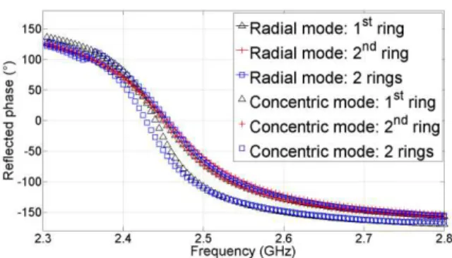
phase frequency. So, as an example, two circular HIS rings are considered as shown in Fig. 7. The first ring, the inner one, is composed of N=6 patches and is designed alone, being characterized like in previous sections. Dimensions wp, lp, gw
and gl are adjusted in such a way that the reflected phase of
concentric and radial modes is null at 2.45GHz. According to Fig. 7, dimensions are the following: lp=28.3mm, wp=24.2mm,
gw=2.6mm, gl=1.3mm, with the same substrate than earlier.
Using eq. 1, the inner radius is found to be 10.79mm and so the outer one is 40.39mm. Results regarding the reflected phase can be observed in Fig. 8. Both the modes exhibit a null phase at approximately 2.45GHz. However, it can be observed that the +/-90° phase bandwidth of the radial mode (5.09%) is wider than the concentric one (3.69%).
Fig. 7 - Two rings HIS (lp=28.3mm, wp=24.2mm, gw=2.6mm, gl=1.3mm,
lp2=26.5mm, gw2=2.3mm, gl2=1.5mm)
Then, the outer ring, composed of N=12 patches, is designed. The method is now slightly different. For the inner ring, the radius is determined according to the desired patch dimensions. Here, the outer ring radius is fixed by the inner one. So simulations are conducted on the outer ring alone and the dimension lp2 is adjusted in order to obtain a radial mode
resonance at 2.45GHz. Then, by adjusting gw2, the concentric
mode resonance is also set to 2.45GHz. Here, the gap gl2 is
chosen arbitrarily at gl2=1.5mm and has not been used to set
the radial mode response (it could have been used within the same way as the parameter lp2). Dimensions are found to be:
lp2=26.5mm, gw2=2.3mm. The reflected phase of the outer ring
is plotted in Fig. 8. Both the modes exhibit a null phase at 2.45GHz. Bandwidths are more similar between each other than those of the first ring. The radial mode has a bandwidth of 6.5% and the concentric mode a bandwidth of 5.8%.
After the design of both the single rings, the simulation of the whole circular HIS, as presented in Fig. 7, is carried on and results are shown in Fig. 8. As expected, the null phase frequency of both the modes is similar to the single rings one. This observation validates the following in the characterization of circular HIS: to simulate and to design different rings independently or all together lead to similar results. However, unlike cartesian lattices for which only one unit-cell simulation is performed to predict the response of the complete metasurface, it is necessary to simulate each ring to ensure all of them exhibit the same null phase frequency.
Fig. 8 – Reflected phase diagram of the two-rings HIS V. CONCLUSION
In this letter, the waveguide-based reflection phase method is used to characterize circular High-Impedance Surfaces (HIS). Using a coaxial waveguide structure, the reflected phase can be determined for incident waves with concentric or radial polarization. The HIS is composed of a patch array arranged along a circular lattice over a grounded dielectric substrate without via. Effects of the geometrical dimensions of the circular HIS have been investigated and differences with a cartesian lattice have been highlighted. It has been shown that designing a circular HIS is more complicated than designing a cartesian HIS because of the curvature’s effect. Thus, the proposed characterization is suitable to obtain the desired reflected phase response of a circular HIS for a possible integration with a circularly polarized antenna. The last section of the letter detailed the design methodology of a complete circular HIS.
REFERENCES
[1] D. Sievenpiper, L. Zhang, R.F. Jimenez Broas, N.G. Alexopolous and E. Yablonovitch “High-Impedance Electromagnetic Surfaces with a Forbidden Frequency Band”, IEEE Trans. Microw. Theory and Tech., vol. 47, no. 11, pp. 2059-2074, Nov. 1999.
[2] F. Yang and Y. Rahmat-Samii, “Electromagnetic Band Gap Structures in Antenna Engineering”, Cambridge University Press, 2009
[3] A. Foroozesh and L. Shafai, “Investigation Into the Application of Artificial Magnetic Conductors to Bandwidth Broadening, Gain Enhancement and Beam Shaping of Low Profile and Conventional Monopole Antennas”, IEEE Trans. Ant. Propag., vol. 59, no. 1, pp. 4-20, Jan. 2011.
[4] N. Llombart, A. Neto, G. Gerini and P. de Maagt, “Planar Circularly Symmetric EBG Structures for Reducing Surface Waves in Printed Antennas” ”, IEEE Trans. Ant. Propag., vol. 53, no. 10, pp. 3210-3218, Oct. 2005.
[5] G. Ruvio, M.J. Ammann and X. Bao, “Radial EBG cell layout for GPS patch Antennas”, Elec. Lett., vol. 45, no. 13, pp. 663-664, June 2009. [6] D. Yan, Q. Gao, C. Wang, and N. Yuan, “Strip-Type AMC Structure
and Analysis to Its Band-Gap Characteristic”, PIERS, vol. 1, no. 5, pp. 505-509, Aug. 2005.
[7] F. Yang and Y. Rahmat-Samii, “Reflection Phase Characterizations of the EBG Ground Plane for Low Profile Wire Antenna Applications”,
IEEE Trans. Ant. Propag., vol. 51, no. 10, pp. 2691-2703, Oct. 2003.
[8] O. Luukkonen, C. Simovski, G. Granet, G. Goussetis, D. Lioubtchenko, A.V. Räisänen and S. A. Tretyakov, “Simple and Accurate Analytical Model of Planar Grids and High-Impedance Surfaces Comprising Metal Strips or Patches”, IEEE Trans. Ant. Propag., vol. 56, no. 6, pp. 1624-1632, June 2008.
[9] W. Yu, D.H. Werner and R. Mittra, “Reflection Characteristic Analysis of an Artificially Synthesized Absorbing Medium”, IEEE Trans.
Magnetics, vol. 37, no. 5, pp. 3798-3802, Sep. 2001.
[10] Y. Zhang, J. von Hagen, M.Younis, C. Fischer and W. Wiesbeck “Planar Artificial Magnetic Conductors and Patch Antennas”, Trans. Ant.