HAL Id: hal-01184185
https://hal.archives-ouvertes.fr/hal-01184185
Submitted on 13 Aug 2015
HAL is a multi-disciplinary open access
archive for the deposit and dissemination of
sci-entific research documents, whether they are
pub-lished or not. The documents may come from
teaching and research institutions in France or
abroad, or from public or private research centers.
L’archive ouverte pluridisciplinaire HAL, est
destinée au dépôt et à la diffusion de documents
scientifiques de niveau recherche, publiés ou non,
émanant des établissements d’enseignement et de
recherche français ou étrangers, des laboratoires
publics ou privés.
LSP Setup Arrival Reordering Approach for MPLS-TE
Routing
Imène Chaieb, Jean-Louis Le Roux, Bernard Cousin
To cite this version:
Imène Chaieb, Jean-Louis Le Roux, Bernard Cousin. LSP Setup Arrival Reordering Approach for
MPLS-TE Routing. IEEE Global Telecommunications Conference (Globecom 2007), Nov 2007,
Wash-ington, United States. pp.432-437, �10.1109/GLOCOM.2007.87�. �hal-01184185�
LSP Setup Arrival Reordering Approach for
MPLS-TE Routing
Im`ene Chaieb and Jean-Louis Le Roux
France Telecom R&D, Lannion 22307, France Email:{imene.chaieb, jeanlouis.leroux}@orange-ftgroup.com
Bernard Cousin
IRISA, Rennes 35042, France Email: bernard.cousin@irisa.fr
Abstract— In this paper, we evaluate a solution based on
the preemption mechanism so as to improve performances of distributed Multi-Protocol Label Switching-Traffic Engineering (MPLS-TE) path computation, where requests are handled one by one, in an uncoordinated manner without any knowledge of future and other requests. Our solution is motivated by the considerable impact of the tunnel setup order on the network load and blocking probability. If it is not possible to control this order, in return it is possible, in some cases, to reorder requests using the pre-emption function. After evaluating the impact of the tunnel setup order, we study the use of preemption to reorder LSP setup, with various algorithms, including Shortest Path First (SPF), Widest Shortest Path (WSP) and Shortest Widest Path (SWP). We show that the preemption is well suited to shortest path based algorithms and the performances in terms of blocking rate are significantly improved.
I. INTRODUCTION
The emergence of MPLS has overcome the limitations of classical IP routing relying on a destination based routing paradigm. With MPLS forwarding relies on a fixed length label inserted before the IP header. MPLS allows for explicit routing and hence can be used for traffic engineering. This results in the MPLS-TE approach [1] which allows setting up explicitly routed Traffic Engineering-Label Switched Paths (TE-LSP) that satisfy a set of traffic engineering constraints, including bandwidth and delay. MPLS-TE combines explicit routing capabilities of MPLS with a Constraint Based Routing (CBR) mechanism that lies in dynamic resources discovery (ISIS-TE [2], OSPF-(ISIS-TE [3]), constrained path computation, and distributed LSP signalling with resource reservation (RSVP-TE) [4]. MPLS-TE provides network resource optimization, while ensuring quality of service (QoS). There are various MPLS-TE routing options, which differ with the location of path computation elements (distributed on edge routers or centralized on a server), the path computation time scale (offline or online) and the level of coordination (paths can be computed either one by one independently of each other, or in a coordinated manner). Among those, the option mainly deployed today by operators is the Online Uncoordinated Dis-tributed one [5], where the LSP setup requests are handled one by one by the edge routers in an uncoordinated manner. This approach offers better scalability, reactivity and robustness than the Offline Coordinated Centralized mode where a server is in charge of computing all the LSPs in a coordinated manner without any time limitation. In return, with the uncoordinated
approach, an edge router does not have a global knowledge of all LSPs established by other edge routers, and hence the performances in terms of optimality are affected. In some cases this mode even fails to find a path for all requests while there is a feasible solution. A basic uncoordinated path computation algorithm implemented today in most of routers relies on a modified Dijkstra algorithm [6]: links that do not support the constraints are pruned from the topology and the Dijkstra SPF algorithm is run on the resulting topology. This algorithm also referred to as CSPF (Constrained Shortest Path First) is by nature heavily greedy, and rapidly leads to blocking issues. In order to overcome these CSPF limitations, a set of solutions have been proposed in the literature that reduces the blocking probability and achieves better resources optimization while keeping agility characteristics (robustness, scalability and reactivity) of the uncoordinated scheme. These solutions try to find the best weight or cost function to be used by the routing algorithm in order to minimize congestion. This includes, non exhaustively: the Widest Shortest Path Algorithm (WSP) [7], the Shortest Widest Path Algorithm (SWP) [8], the Minimum Interference Routing Algorithm (MIRA) [9], the Dynamic Online Routing Algorithm (DORA) and the Profile Based Routing (PBR) algorithm. Actually in the uncoordinated mode, the arrival order of the LSP requests is critical, two distinct orders are likely to provide distinct blocking results and this is actually a major characteristic of all uncoordinated algorithms including those listed above. In this paper, we focus on the LSP request arrival order. We firstly evaluate in section II the impact of the LSP arrival order on the blocking probability and we try to identify relevant orders. In section III, we describe the MPLS-TE pre-emption mechanism that allows a new LSP to delete an existing LSP which is rerouted on an alternate path, and hence can be used as a solution to reorder the LSP arrivals. Then, we propose two pre-emption strategies to control the reordering of LSPs and show that this cannot be applied to all algorithms. Finally, the section V provides evaluation of these strategies in terms of link utilization and blocking rate, when applied to CSPF, WSP and SWP algorithms.
II. IMPACT OFLSPSETUP ARRIVAL ORDER ON ROUTING
PERFORMANCES
As previously discussed, in the uncoordinated MPLS-TE mode the LSP requests are computed one-by-one without any
knowledge of other requests. This can lead to a sub-optimal solution, where some LSP requests can be rejected even if there is a feasible placement.
We illustrate this with a simple example. Consider the network in Fig. 1. Each link is characterized by its metric (1 unit for all links) and its capacity (in Mbps). Six LSP setup requests with bandwidth size BW (in Mbps), as shown in table I, arrive at node 1 one-by-one with node 6 as destination. The Fig.
LSP L1 L2 L3 L4 L5 L6 Bandwidth (BW) 30 25 35 16 17 20
TABLE I
ILLUSTRATION: THE BANDWIDTH OFLSPREQUESTS
2 shows the number of rejected LSPs on the network for all possible permutations of these 6 requests, according to their bandwidth size. LSPs path computation is done using the CSPF, the SWP and the WSP algorithms. With the three algorithms we observe a maximum of 2 rejections (ie 33%), and an average of 1 rejection (ie 17%). The increasing order (according to LSPs bandwidth) achieves0 rejection with CSPF while there is1 rejection with SWP and WSP. The decreasing order rejects 1 request with CSPF and SWP and 2 requests with WSP. It can be seen that the increasing order performs equal or better than the decreasing order. This result can be explained as follows; since in the decreasing case, the large LSPs are established first, they may block the resources on shortest and non shortest paths. So, some of the small LSPs which arrive after may be rejected. However, in the increasing case, small LSPs are established first and more LSPs can be accepted before reaching congestion case. This example illustrates the limitation of the distributed uncoordinated rout-ing scheme in terms of optimization performances. It also shows the impact of the LSP request setup order on the routing performances; we notice that with the same topology, the same requests and the same routing algorithm (CSPF, SWP or WSP), the routing performance varies with the LSP arrival order. In this specific example, there are 6 requests, so there are 720 (6!) possible orders. The computation of an optimal order, that is an order which minimizes the number of rejected requests, requires the knowledge of all orders, this has an exponential complexity; and cannot be performed. In return we can identify relevant orders, such as for instance the increasing order with CSPF. Hence controlling the LSP setup order would allow improving the performances of the distributed uncoordinated scheme. Of course it is not possible to control the LSP arrival order. In return it is possible in some situations, to reorder LSP setup with the MPLS-TE preemption mechanism described in more details latter.
III. DYNAMIC REORDERING OFLSPS USING PREEMPTION
Once an efficient order is found, the question which arise is how to dynamically control this order, while retaining agility characteristics (reactivity, robustness, scalability) of an Online Distributed Uncoordinated system ? Our approach consists in investigating the use of MPLS-TE preemption so as to dynamically reorder LSPs setup.
6 3 5 4 2 1 35 35 45 45 65 65 65
Fig. 1. Illustrative Example
0 100 200 300 400 500 600 700 0 1 2 0 100 200 300 400 500 600 700 0 1 2 0 100 200 300 400 500 600 700 0 1 2 Permutation Id CSPF WSP SWP
Fig. 2. Illustrative Example: Number of rejected LSPs for all permutations requests (o : Increasing - * : Decreasing,−− : Average of all the permutations)
Preemption mechanism in MPLS system
The RSVP-TE protocol [4] includes a preemption mechanism that allows an LSP with a given priority to preempt an LSP with a lower priority. The lower priority LSP is rerouted on an alternate path and it all happens as if the lower priority LSP had been setup after the higher priority LSP. The RSVP-TE protocol allows specifying two priority attributes: the setup priority that specifies the capability of an LSP to pre-empt another LSP and the holding priority that specifies the capa-bility of an LSP to resist to preemption. Both priorities have a range of0 (highest priority) to 7 (lowest priority). An LSP with higher (numerically lower) setup priority can preempt an LSP with lower (numerically higher) holding priority. To avoid continuous preemptions and oscillations, the holding priority should never be lower (numerically higher) than the setup priority. The IGP-TE advertises different ”unreserved bandwidth” information for each priority level. So, to compute the route for an LSP with priority p, only the unreserved bandwidth for priority p has to be checked. Thus, available bandwidth is checked by considering only the LSPs with same or higher priority and as if LSPs with lower priority did not exist. The preemption mechanism can be used to ensure that mission critical traffic trunks (e.g. VoIP) can always be routed through relatively favorable paths (e.g. shortest path) and can preempt best effort services (e.g Internet data) upon congestion or failure event. In [10], the authors propose a flexible policy to achieve various objectives when selecting the set of LSPs to be
preempted. Preemption can also be used so as to dynamically reorder the LSP setup, indeed a higher priority LSP is routed as if the lower LSP did not exist. A solution to enforce a specific LSP setup order consists of assigning priorities to LSPs based on their bandwidth. For instance, if we want to apply an increasing bandwidth LSP setup order, low bandwidth LSPs should have a higher priority than high bandwidth LSPs. Let’s take the example in section II and assume that the increasing order has to be applied. For that purpose we assign to each LSP a priority P, as shown in table II.
LSP L1 L2 L3 L4 L5 L6 Bandwidth (BW) 30 25 35 16 17 20 Priority (P) 6 5 7 0 2 3
TABLE II
ILLUSTRATION: THE BANDWIDTH AND PRIORITY OFLSPREQUESTS
Table III gives the details about the path computation of each LSP. For each LSP, it indicates its route or its rejection and the LSPs preempted by this LSP. For example, with WSP algorithm, the setup of LSP4 which takes the route1 − 3 − 6 induces the preemption of LSP2 that itself preempts LSP1 (preemption cascade). The table shows also that to setup 6 LSPs, 8 LSPs have been preempted using the SWP, 7 LSPs using the WSP and only 3 LSPs using the CSPF. In fact, in CSPF case and more generally in shortest path based algorithms, the preemption mechanism can be easily applied and is not very heavy in terms of number of preemptions because the preemption should be done only when there is no available resource on a link of the shortest path. However, when using widest path based algorithms (eg. WSP and SWP), the preemption mechanism cannot be applied because it does not scale with the number of LSP requests. In fact, the preemption should be done even if there is available resource on a link of the selected path because the optimization metrics in this case include the available bandwidth. So when an LSP with high priority is routed through a link, and even if there are still sufficient resources to maintain lower priority LSPs that are already routed through this link, these LSPs have to be re-routed because the available bandwidth is changed when the higher LSP is established and the path may no longer be a widest path. Consequently, we cannot apply pre-emption based reordering with widest path based algorithms (WSP, SWP).
There areN LSP setup requests and only 8 priorities (8 << N), we cannot assign a different priority to each LSP, and hence we cannot apply an exact order (this would requireN priorities). So, the problem which arises now is how to allocate the 8 priorities to the N LSPs. We need to find an efficient way to allocate a priority to each LSP.
We propose here two methods: the Linear Repartition (LR) and the Non-Linear Repartition (NLR).
A. Linear Repartition (LR)
This technique consists of the following steps:
CSPF SWP WSP LSP1 1 − 2 − 6 1 − 4 − 5 − 6 1 − 3 − 6 LSP2 1 − 2 − 6 1 − 4 − 5 − 6 1 − 3 − 6 LSP1:1 − 3 − 6 LSP1:1 − 3 − 6 LSP1:1 − 2 − 6 LSP3 1 − 4 − 5 − 6 1 − 4 − 5 − 6 1 − 4 − 5 − 6 LSP4 1 − 2 − 6 1 − 4 − 5 − 6 1 − 3 − 6 LSP2:1 − 3 − 6 LSP2:1−4−5−6 LSP2:1 − 2 − 6 LSP1:1−4−5−6 LSP3:1 − 2 − 6 LSP1:1−4−5−6 LSP5 1 − 2 − 6 1 − 4 − 5 − 6 1 − 2 − 6 LSP2:1 − 3 − 6 LSP2 :1 − 3 − 6 LSP1:1 − 2 − 6 LSP3: Rejected LSP6 1 − 3 − 6 1 − 3 − 6 1 − 3 − 6 LSP2:1 − 2 − 6 LSP2:1−4−5−6 LSP1:1−4−5−6 LSP1:1−4−5−6 LSP3 : Rejected TABLE III
ILLUSTRATIVEEXAMPLE: PREEMPTION MECHANISM USINGCSPF, WSP
ANDSWP
• Sort the LSP requests (e.g. in increasing order)
• Equally divide the scale of the requests’s bandwidth in 8 intervals, the width of each interval is Bi = (Bmax− Bmin)/8 where:
Bmax: The bandwidth of the largest LSP demand.
Bmin: The bandwidth of the smallest LSP demand.
and0 <= i <= 7.
• Assign a priorityP rio to each interval: Assign the same priority to all LSPs whose size belongs to the same interval. If an increasing order is required then:
Bw(lsp) ∈ [Bi, Bi+1] => P rio(lsp) = i
If a decreasing order is required then: Bw(lsp) ∈ [Bi, Bi+1] => P rio(lsp) = 7 − i
Note that LSPs within the same bandwidth interval have the same priority and cannot be ordered.
With this approach, LSPs are not equally spread among all priorities; there may be a lot of LSPs with same priority, which can not be ordered.
B. Non-Linear Repartition (NLR)
The first approach may lead to an unequal repartition of LSPs between the 8 intervals. Thus, we investigate a second approach which takes into account the number of LSPs per priority level. It assigns to each set of N/8 LSPs the same priority (N is the number of requests). It proceeds as follow:
• Sort the LSP requests (e.g. in increasing order)
• Divide the scale of requests in 8 intervals, each interval Bi includesn = N/8 LSPs.
• Assign a priority P rio to each interval: A1locate the priorityP rio to all n LSPs within this interval.
Priority configuration
In order to apply the preemption mechanism, LSP priorities should be known on the ingress LSRs. There are two options: Priorities may be determined on a TE server and then configured on the Ingress routers, or they may be dynamically computed on the Ingress routers. In the LR case, the network administrator can determine a lower bound for Bmin and an upper bound for Bmax, which are then configured on
Fig. 3. The network topology
all Ingress routers. Ingress routers can dynamically apply a priority to an LSP according to its bandwidth, following the LR formula. This allows for dynamic LSP bandwidth modification on Ingress LSRs that adapt LSP priorities accordingly. In the NLR case, priority allocation requires knowledge of all LSPs and their bandwidth and hence cannot be performed on Ingress routers (see section III). In this case priorities must be allocated by the TE server that then configures LSPs with theirs priorities on Ingress LSRs. This approach does not allow dynamic LSP bandwidth modification on the Ingress LSR, as the Ingress LSR has not enough information to modify the LSP priority accordingly. In a nutshell, the LR approach is well suited to an online distributed mode while the NLR approach better fits in with an offline centralized approach.
IV. EVALUATION
In this section, we numerically evaluate our approach. All the simulations shown in the remainder of the paper are carried out using the network topology that was proposed in [9], see Fig. 3. This topology includes 15 nodes and 28 bidirectional links. The capacity of the thin links is12∗100 units and that of the fat links is48∗100 units (taken to model the capacity ratio of OC-12 and OC-48 links and scaled by 100). We show the performances of our approach using the Constrained Shortest Path First algorithm (CSPF). All experiments are made under the following assumptions:
• We assume that all LSPs are long lived (”static” case).
• We construct a full mesh of LSPs between edge routers, by loading the network with 840 LSPs = 15 ∗ 14 ∗ 4 = Ner∗ (Ner− 1) ∗ Nl, withNer is the number of edges
routers andNlis the number of established LSPs between each edge routers pairs.
• We multiply the LSP’s bandwidth by an increasing Traffic Scale factor k to vary the network load conditions.
• For each value of k, we conduct 100 trials by gener-ating randomly 840 requests with bandwidth demands uniformly distributed between 1 and 50 Mbps.
The following metrics are used to evaluate our approach:
• Maximum link load: maxiBWi/Ci, where Ci is the capacity of a link i and BWi is the amount of traffic
carried on this link.
• Rejected LSP ratio: The percentage of requests which are rejected due to insufficient resources.
• Rejected Bandwidth Quantity: The total amount of band-width which is rejected due to insufficient resources. A. Order Impact
The following notations are used in the remainder of the paper:
• CSPF: CSPF without LSPs reordering
• CSPF-IB-EO: CSPF with increasing bandwidth exact
order
• CSPF-DB-EO: CSPF with decreasing bandwidth exact
order
• CSPF-IB-LR-PO-CSPF: CSPF with increasing
band-width linear repartition preemption based order
• CSPF-IB-NLR-PO: CSPF with increasing bandwidth non linear repartition preemption based order
Fig. 4 shows the average maximum link load in the network after establishing840 LSPs in random, increasing and decreas-ing bandwidth orders with CSPF, and usdecreas-ing WSP and SWP algorithms. We see that IB-EO-CSPF outperforms the CSPF and the DB-EO-CSPF. This result can be explained as follows; In the decreasing case, the large LSPs are setup on shortest paths, the small LSPs requests arrive after and they fill the remaining bandwidth on shortest paths, thus increasing the maximum link load. However, in the increasing case, small LSPs are established at first and are routed through shortest paths and there is no longer enough bandwidth on shortest paths to route larger LSPs which are routed on non shortest paths. These non shortest paths are usually larger than the shortest paths after routing small LSPs. Thus, the residual bandwidth on shortest paths is larger in the increasing case (bandwidth which cannot fit large LSPs) than in the decreasing case (bandwidth which cannot fit small LSPs). In return, the gain remains negligible compared to the performances of the WSP and the SWP; the IB-EO-CSPF reaches an average better performance of about only 0.6% over the CSPF (while WSP and SWP are about respectively8% and 20% better than the CSPF). We see also with the CSPF that, from k = 0.7 the rising scheme of the maximum link load slows down. This is due to the fact that the non shortest paths start to be used to route some LSP requests. SWP and WSP try to avoid overloading some links, this explains the significantly better performances in terms of maximum load.
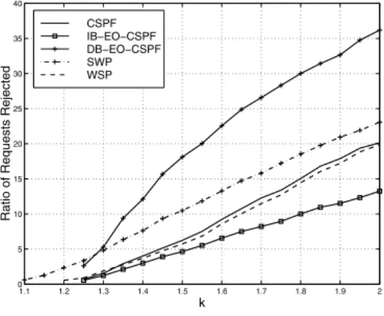
Fig. 5 depicts the average LSP rejection ratio. It can be observed that the increasing order performs better than the decreasing and the random cases. The figure shows also that the IB-EO-CSPF performs significantly better than CSPF, WSP and SWP algorithms. Indeed, in the random case large LSPs may arrive before small LSPs and block resources for subsequent LSPs requests. For instance, for k = 1.8, the IB-EO-CSPF rejects about 45% less than SWP, 35% less than
0.6 0.7 0.8 0.9 1 1.1 1.2 1.3 60 65 70 75 80 85 90 95 100 105 110 Maximum Load k CSPF IB−EO−CSPF DB−EO−CSPF SWP WSP
Fig. 4. Average Maximum Link Load vs. k
also observe that the SWP is the first at rejecting LSPs (from k = 1.1). In return, the WSP starts to reject LSP from k = 1.2 and the CSPF rejects LSPs fromk = 1.25.
Fig. 6 shows the average amount of bandwidth rejected. Firstly we see that the decreasing order outperforms the increasing order. Actually in the increasing case, large LSPs are rejected in blocking cases, so the quantity of bandwidth rejected can be more important than in decreasing case where small LSPs are rejected. We can see that the gain offered by the DB-EO-CSPF is actually not significant. The IB-EO-CSPF rejects only 5% more bandwidth while it allows 63% less LSP rejection than the DB-EO-CSPF. Hence we can conclude that in this example the IB-EO-CSPF allows achieving good performances. 1.1 1.2 1.3 1.4 1.5 1.6 1.7 1.8 1.9 2 0 5 10 15 20 25 30 35 40
Ratio of Requests Rejected
k CSPF IB−EO−CSPF DB−EO−CSPF SWP WSP
Fig. 5. Average Rejected LSP Ratio vs. k
So, we observe that the CSPF increasing order offers significantly better performances in terms of rejected LSP ratio, than the CSPF decreasing order, but rejects slightly more bandwidth. An operator can choose the criteria (rejected LSPs number or rejected bandwidth) which seems more important and consequently decide to apply either the increasing or the decreasing order.
B. Preemption based reordering
Fig. 7 presents the performances in terms of maximum link load of the CSPF when we introduce the preemption
1.1 1.2 1.3 1.4 1.5 1.6 1.7 1.8 1.9 2 0 2 4 6 8 10 12x 10 6
Quantity of bandwidth Rejected
k WSP DB−EO−CSPF CSPF IB−EO−CSPF SWP
Fig. 6. Average Quantity of Bandwidth rejected Ratio vs. k
mechanism to apply the increasing order. Firstly, we can see that the performances of IB-LR-PO-CSPF and IB-NLR-PO-CSPF are close to those of IB-EO-IB-NLR-PO-CSPF. So, our proposed repartitions appear to be really efficient to dynamically re-order LSP requests. It can be seen also that the IB-NLR-PO-CSPF is slightly better than the IB-LR-IB-NLR-PO-CSPF and sometimes even better than the IB-EO-CSPF (fork = 0.95). In fact, this depends on the LSP bandwidth distribution. The optimal order is not necessary the IB order, such as for k = 0.95 where the LR preemption order is closer to the optimal order than the exact increasing order.
0.6 0.7 0.8 0.9 1 1.1 1.2 1.3 97 97.5 98 98.5 99 99.5 100 Maximum Load k CSPF IB−EO−CSPF IB−LR−PO−CSPF IB−NLR−PO−CSPF
Fig. 7. Average Maximum Link Load vs. k with Linear and Non linear Repartition
The results in Fig. 8 show firstly that the LR and NLR methods provide similar results in term of rejected LSP ratio. Secondly, it can be seen that IB-LR-PO-CSPF and IB-NLR-PO-CSPF are less efficient than the IB-EO-CSPF but improve significantly, the performances of the CSPF placement. Ac-tually, IB-LR-PO-CSPF and IB-NLR-PO-CSPF reject about 30% less than the CSPF but 13% more than IB-EO-CSPF. Clearly, the preemption reordering applied to CSPF leads to a significant reduction of LSP rejections.
C. Network Failure Case
Now we evaluate the performances of CSPF with our approach when a link failure happens. For a given Traffic
1.2 1.4 1.6 1.8 2 0 5 10 15 20 25
Ratio of Requests Rejected
k
CSPF IB−EO−CSPF IB−LR−PO−CSPF IB−NLR−PO−CSPF
Fig. 8. Rejected LSP Ratio vs. k with Linear and Nolinear Repartition
Scale Factor k, we load the network with 840 LSPs routed using the CSPF, IB-LR-PO-CSPF and IB-NLR-PO-CSPF. The network load is sufficiently low, so all LSPs are established without any rejection case. We then cut randomly a link (edge or core link) and re-route all the LSPs traversing this link. We proceed as follows100 times, and each time, 840 LSP requests are randomly generated. Note that the LSPs rejected when using the CSPF are a subset or all the LSPs impacted by the failure (the LSPs routed through the failing link). In return, the LSPs rejected when using IB-LR-PO-CSPF and IB-NLR-PO-CSPF may include LSPs which have not been impacted by the failure. Actually, when a failure occurs, the LSPs impacted by the failure will be rerouted by Ingress routers. These impacted LSPs may preempt, on their new paths, lower priority LSPs which have not actually been directly impacted by the failure. Hence, after a network failure, such lower priority LSPs will be rerouted and potentially rejected if there are no sufficient resources. Table IV shows the average number of rejected LSPs with CSPF, IB-LR-PO-CSPF and IB-NLR-PO-CSPF for some failure cases. It also shows the average number of LSPs impacted by the failure (Imp) as well as the average number of LSPs not impacted by the failure (NoImp), among the rejected LSPs.
Failed Link CSPF IB-EO IB-LR-PO IB-NLR-PO Imp NoImp Imp NoImp 14 − 15 28.42 12.17 12.26 12.27 7.62 4.64 7.66 4.61 12 − 13 5.78 0.0 0.0 0.0 0.0 0.0 0.0 0.0 8 − 9 12.02 7.32 7.38 7.40 2.54 4.84 2.54 4.86 2 − 5 25.78 13.0 13.29 13.23 6.01 7.28 5.62 7.31 TABLE IV
AVERAGENUMBER OF REJECTEDREQUESTS UNDER LINK FAILURE USING
CSPF ALGORITHM
In this experiment, requests are generated with k = 1.05. It can be seen that the re-ordering approach (LR or NLR) allows significant reduction in the number of rejections upon
network failures. For instance, when the link14 − 15 is cut, there are 2.3 times less rejections with preemption based reordering, than in the random case (without reordering). 2/3 of rejected LSP requests include LSPs impacted by the failure and 1/3 of rejected LSP requests include LSPs non impacted by the failure. Also in some cases the reordering allows avoiding rejection (e.g. link 12-13 failure), which is a significant improvement.
V. CONCLUSION
In this paper we have analyzed the impact of the LSP setup order on the optimization performances of an uncoordinated distributed MPLS-TE routing system. We have observed that if the LSPs are setup in increasing bandwidth order then the LSP rejection is significantly reduced . We have discussed the use of preemption so as to dynamically reorder LSPs setup and we have proposed two approaches to allocate one of the eight preemption priorities to an LSP, according to its bandwidth. We have evaluated these approaches and observed that the use of preemption to enforce an increasing LSP setup order allows achieving a really significant reduction of the number of LSP rejections compared to CSPF, WSP and SWP, with a very small increase in the amount of bandwidth rejected. Moreover, as regards maximum link load, the improvement is negligible. These preemption approaches cannot be applied to WSP and WSP algorithms, because this always triggers cascaded preemption. As future work, we plan to evaluate the impact of the preemption on the network control plane and propose solutions to reduce this impact (in particular reduce the number of preemptions globally and per LSP). Also, we plan to evaluate the impact of the LSP bandwidth distribution (e.g. linear, gaussian) on the performances of the LR and NLR approaches.
REFERENCES
[1] D. Awduche and B. Jabbari, “Internet traffic engineering using multi-protocol label switching (MPLS),” Computer Networks, 2002. [2] H. Smit and T. Li, “IS-IS extensions for traffic engineering,” RFC 3784,
June 2004.
[3] D. Katz, K. Kompella, and D. Yeung, “Traffic engineering (TE) exten-sions to OSPF version 2,” RFC 3630, 2003.
[4] D. Awduche, L. Berger, D. Gan, T. Li, V. Srinivasan, and G. Swallow, “RSVP-TE: Extensions to RSVP for LSP tunnels,” RFC 3209, 2001. [5] I. Chaieb, J.L. Le Roux, and B. Cousin, “Generic architecture for
MPLS-TE routing,” CIIT 2006, 2006.
[6] T. Corman, C. Leiserson, and R. Rivest, Introduction to Algorithms. MIT Press, 1990.
[7] R. Guerin, A. Orda, and D. Williams, “Qos routing mechanisms and OSPF extensions,” In Proceedings of 2nd Global Internet
Miniconfer-ence (joint with Globecom97), 1997.
[8] Z. Wang and J. Crowcroft, “Quality-of-service routing for supporting multimedia applications,” IEEE J-SAC, 1996.
[9] T. L. M. Kodialam, “Minimum interference routing with applications to MPLS traffic engineering,” in INFOCOM, 2000.
[10] J. de Oliveira, C. Scoglio, I. Akyildiz, and G. Uhl, “A new preemption policy for diffserv-aware traffic engineering to minimize rerouting,”