Ministry of higher Education and
Scientific Research
University Echahid Hamma Lakhdar of El-Oued
Faculty of Technology
Report Presented in Partial Fulfilment
Of the Requirements of the
MASTER ACADEMIC
Domain: Technology
Option: Electrical Engineering
Specialist: Electrics Machines
Thesis
Supervised by: Realised by:
Dr. SEHOUD Hicham LAMA Abdelbadia
Sensorless Optimal Power Control of Doubly Fed
Induction Generator in Variable Speed Wind
Turbine System
i
The present work is an aims to study a sensorless power control of the doubly fed induction generator (DFIG) in wind energy conversion system (WECS) without speed sensors based of application of the MRAS technique for estimation of rotor speed, the stator flux oriented vector control (technique) is used for control active and reactive power. The simulation results in MATLAB/Simulink platform verify the good static and dynamic performance of this sensorless power control for DFIG in variable speed wind turbines.
Keywords
Doubly fed induction generator (DFIG), Vector control, PWM converter, Maximum power point tracking (MPPT), MRAS observer.
Résumé
Le travail présent la commande vectorielle sans capteur mécanique de la machine asynchrone à double alimentation (MADA) intégrée dans un système éolien basé sur un système adaptatif à modèle de référence (MRAS). La commande vectorielle par orientation de flux statorique est utilisé pour contrôlé la puissance active et la puissance réactive. Les résultats de simulation numériques à base du logiciel Matlab/Simulink vérifié les bonnes performances statiques et dynamiques de cette commande.
Mots clés:
GADA, Commande vectorielle sans capteur, convertisseur MLI, Commande MPPT, Observateur MRAS.
ا
ﺺﯿﺨﻠّﺘﻟ
:
ﺪﻟﻮﻤﻟ ﺮﻌﺸﺘﺴﻣ نوﺪﺑ ﺔﻗﺎﻄﻟا ﻲﻓ ﻢﻜﺤﺘﻟا ﺔﺳارد ﻰﻟإ ﻲﻟﺎﺤﻟا ﻞﻤﻌﻟا فﺪﮭﯾ ﻲﻨﻣاﺰﺗ ﻻ ﻲﺋاﻮھ ﺔﯾﺬﻐﺘﻟا جودﺰﻣ مﺎﻈﻧ ﻲﻓ حﺎﯾﺮﻟا ﺔﻗﺎط ﻞﯾﻮﺤﺗ ﺔﯿﻨﻘﺗ ﻖﯿﺒﻄﺗ ﻰﻟإ اًدﺎﻨﺘﺳا ﺔﻋﺮﺴﻟا تاﺮﻌﺸﺘﺴﻣ نوﺪﺑ ﻲﺟذﻮﻤﻨﻟا ﻲﻌﺟﺮﻤﻟا ﻒﯿﻜﺘﻟا مﺎﻈﻧ MRAS ﺮﯾﺪﻘﺘﻟ ،راوﺪﻟا ﺔﻋﺮﺳ ﻟا ﻲﻓ ﻢّﻜﺤﺘ ﻹا عﺎﻌﺷ ﻟا ﮫ ّﺟﻮﻤ ﻟ ﺖﺑﺎﺜﻟا ءﺰﺠﻟا ﻖﻓﺪﺘ ا مﺪﺨﺘﺳ ﻲﻓ ﺔﯿﻨﻘﺗ ﻢﻜﺤﺘﻟا ةﻮﻘﻟا ﻰﻠﻋ ةﺮﻄﯿﺴﻠﻟ ﺔﯿﻠﻋﺎﻔﺘﻟاو ﺔﻄﺸﻨﻟا . ةﺎﻛﺎﺤﻤﻟا ﺞﺋﺎﺘﻧ ﻖﻘﺤﺗ ﻲﺘﻟا ﺔﺌﯿﺑ ﺖﺤﺗ ﺎھزﺎﺠﻧإ ﻢﺗ Matlab/Simulink ﻢﻜﺤﺘﻟا ﺮﺼﻨﻌﻟ ﻲﻜﯿﻣﺎﻨﯾﺪﻟاو ﺖﺑﺎﺜﻟا ءادﻷا ﻦﻣ ﻞﺟأ ﻦﻣ ﺮﻌﺸﺘﺴﻣ نوﺪﺑ ﺔﻗﺎﻄﻟا ﻲﻓ ﺪﻟﻮﻣ ﻲﻨﻣاﺰﺗ ﻻ ﻲﺋاﻮھ ﺔﯾﺬﻐﺘﻟا جودﺰﻣ تﺎﻨﯿﺑرﻮﺗ ﻲﻓ ةﺮﯿﻐﺘﻤﻟا ﺔﻌﯾﺮﺴﻟا حﺎﯾﺮﻟا .ﺔﯿﺣﺎﺘﻔﻣ تﺎﻤﻠﻛ
:
حﺎﯾﺮﻟا ﺔﻗﺎط , ﺔﯾﺬﻐﺘﻟا جودﺰﻣ ﻲﻨﻣاﺰﺗ ﻼﻟا ﺪﻟﻮﻤﻟا , ﯿﺟﻮﺗ ﻖﯾﺮط ﻦﻋ ﻲﻋﺎﻌﺸﻟا ﻢﻜﺤﺘﻟا ﮫ ﻖﻓﺪﺘﻟا , ﻮﺤﻤﻟا ل ,PWM مﺎﻈﻧ ﻲﺟذﻮﻤﻨﻟا ﻲﻌﺟﺮﻤﻟا ﻒﯿﻜﺘﻟا ,MRAS ﺔﯿﺋاﻮﮭﻟا ﺔﻔﻨﻌﻟا ﺎﮭﻤﻜﺤﺗو .MPPTii
Acknowledgements
First, and foremost, I would like to express my deepest appreciation to
our academic advisor Dr. SERHOUD Hicham for his time, expertise and
knowledge that they have given to me during the preparation of this
thesis. It has been a privilege to work under his supervision.
I would also like to thank my parents who have always supported and
believed in me. God bless them.
Thanks also to my family, wife, as they always understood when I was
working and unable to give attention to her and my children.
Finely, Thanks are also to many of my friends and colleagues who have
iii
Acknowledgement
... iiTable of Contents
... iiiList of Symbols
... viList of Figures
... viiiList of Tables
... xGeneral Introduction
... 1Chapter 1: Basics of Wind Power Generation System
1.1. Introduction………..31.2. Renewable energy development...…..……….3
1.3. Wind energy development..……….4
1.4.Basic structure of a wind turbine...………..5
1.5. Classification of wind turbine ………..……….………...6
1.5.1. Vertical axis wind turbine (VAWT)..………6
1.5.2. Horizontal axis wind turbines (HAWT)..…………..………7
1.5.3. Number of blades...…...….………..8
1.5.4. Betz limit...……..………..………...8
1.5.5. Upwind and downwind turbines..………..9
1.6. Wind energy conversion………...………9
1.6.1. Aerodynamic power control.……….………...10
1.6.1.1. Pitch control…...……….…………...10
1.6.1.2.Passive stall regulation………...………..11
1.6.1.3 Active stall regulation...……….………..………..12
1.7. Wind energy conversion system configurations…...13
1.7.1. Fixed speed wind turbine...…………...14
1.7.2. Variable speed wind turbine with reduced capacity converters...………...14
1.7.2.1. Wound rotor induction generator with variable rotor resistance...………...15
1.7.2.2. Doubly fed induction generator with rotor converter….……….……...16
1.7.3. Variable speed wind turbine with full capacity power converters….………...16
1.8. Advantages and disadvantages of wind energy.……….17
iv
1.9. Conclusion...………...18
Chapter 2: Modeling and Vector Control of DFIG
2.1. Introduction………192.2. Components of DFIG…………...…..………..19
2.3. Principle of operation of DFIG………..20
2.3.1. Sub-synchronous mode of operation....………...20
2.3.2 Super-synchronous mode of operation……….………...21
2.4. Advantages and disadvantages of the DFIG………...22
2.4.1. Advantages of the DFIG………..…………..………..22
2.4.2. Disadvantages of the DFIG...………..23
2.5. Modeling of DFIG...………..………...23
2.5.1. Simplifying assumptions..……….……...………...23
2.5.2. Mathematical model of doubly fed induction generator………...………23
2.5.2.1. Electrical equation of DFIG...……….…..………..23
2.5.2.2. Magnetic equations……….………...24
2.5.2.3. Mechanical equations ……….……….25
2.5.3. Doubly fed induction generator model (d-q model)..………...25
2.5.3.1. Park transformation...……….………..………..25
2.5.3.2. Voltages equation...……….………...………..26
2.5.3.3. Flux equation.…………..………...27
2.5.3.4. Electromagnetic torque equation ...27
2.5.3.5. Active and reactive power equations…………...………....………28
2.6. Fundamentals of vector control of induction machines...……….………...………28
2.7. Vector control of doubly fed induction generator……….…..…...29
2.7.1. Stator field oriented of the DFIG………...…..….………..……….29
2.7.2. Control of the rotor side converter (RSC)…...…….………...30
2.7.2.1. Relation between stator and rotor currents…...…...………...………..31
2.7.2.2. Expression of rotor voltage with function of rotor current ………....………..31
2.7.2.3. Expression of active and reactive power of synchronous frame…………....………..32
2.7.3. Control of the grid side converter…...……....…………....…………....……….33
2.7.3.1. Phase locked loop (PLL) type estimator………....…………....……….……...34
v
Chapter 3: MPPT Control for the Proposed Wind Turbine System
3.1. Introduction………38
3.2. Modeling of wind turbine…...…..………...38
3.2.1. The wind velocity………...……….38
3.2.2. Power recoverable by a turbine…………..……….38
3.2.3. The power coefficient………...……….………...40
3.2.4. Model of multiplier………. ....40
3.2.5. Dynamic equation of shaft…..…………..………..……….41
3.3. Scheme of turbine model..………...41
3.4. Control strategy of turbine…………..………...42
3.5. Algorithms for maximizing extracted power……….……….43
3.6. Simulation results………...44
3.7. Conclusion...………...47
Chapter 4: Sensorless Control of DFIG using MRAS
4.1. Introduction………484.2. The different methods of estimating the mechanical speed ………...48
4.2.1. Estimation of the speed with the machine model………..………..48
4.2.2. Estimation of the speed without machine model………...………..49
4.3. Sensorless control of DFIG system using MRAS observer…………...50
4.3.1. The MRAS method……….50
4.3.2. MRAS estimation of mechanical quantities of DFIG….…………..………...51
4.4. Global scheme of the vector control of DFIG without sensors………..53
4.5. Simulation results..………...………...53
4.6 Conclusion………...….………...……….56
General Conclusion
...57Appendices
...58vi MRAS Model reference adaptive system, DFIG Doubly Fed induction generator, GSC Grid side converter,
RSC Rotor side converter, PWM Pulse width modulation,
MPPT Maximum power point tracking, WECS Wind energy conversion system, HAWT Horizontal axis wind turbine, VAWT Vertical axis wind turbine,
SCIG Squirrel cage induction generator, WRIG Wound rotor induction generator,
PMSG Permanent Magnet synchronous generator, PCC Point of common coupling,
PI Proportional integral control AC Alternative current,
DC Direct current,
VSIG Variable speed induction generator, FSIG Fixed speed induction generator,
qs ds v
v , d-q axis stator voltage,
qr dr v
v , d-q axis rotor voltage,
s
vii
r s L
L , Stator and rotor per phase winding inductances,
r s R
R , Stator and rotor per phase winding resistances,
r s P
P , Stator and rotor active power,
r sQ
Q , Stator and rotor reactive power, p Number of machine pair of pole,
Te Electromagnetic torque, Tair Aerodynamic torque,
s
Synchronous rotational speed,
r
Rotor electrical speed,
r
Rotor electrical angle,
r
Rotor electrical angle,
Suffixes, Superscripts
r
s, stator, rotor,
, ,stationary reference frame,
q d, d,q reference frame, c b a ,, Three-phase reference, * Reference value.
viii
Figure 1.1: Worldwide capacity share of different non-hydro renewable powers...………….. 4
Figure 1.2: Global cumulative wind power capacities from 2001 to 2020 ….……….……….. 4
Figure 1.3: Inside of a Wind Turbine ...…...………... 5
Figure 1.4: Typical vertical and horizontal axis wind turbine ………..……. 7
Figure 1.5: Power coefficients (Cp) vs tip speed ratio (λ) for various wind turbines ………… 8
Figure 1.6: Upwind and downwind structure….. ……….. 9
Figure 1.7: Aerodynamic forces and velocities at a rotor blade ……… 10
Figure 1.8: Calculated Cp(λ, β) surface base on real data blade ……..……….. 11
Figure 1.9: Effect for different pitch angles with constant speed operation ………..…… 12
Figure 1.10: Air Flux on a blade profile "stall"……….………. 12
Figure 1.11: Wind energy conversion system without power converter interface .……….….. 14
Figure 1.12: Variable speed configuration with variable rotor resistance……..….…………... 15
Figure 1.13: Variable speed configuration with reduced capacity converters ……….….. 16
Figure 1.14: Variable speed configurations with full capacity converters ….………... 17
Figure 2.1: DFIG based wind Energy conversion system scheme ……… 19
Figure 2.2: Active power flows in the DFIG during sub-synchronous operation...…………... 21
Figure 2.3: Active power flow in the DFIG during super-synchronous operation ……… 22
Figure 2.4: PARK model of DFIG ………. 25
Figure 2.5: Representation of the machine in the two-phase frame ….………. 26
Figure 2.6: General principle of vector control in stator active and reactive power …….…… 28
Figure 2.7: Control architecture of the wind system ………….………. 30
Figure 2.8: Principle of the control of the rotor side converter. ...………..…... 30
Figure 2.9: Control of rotor currents ………...………... 32
Figure 2.10: Control of rotor side converter………..…………. 33
ix
Figure 2.13: Simulation results of a vector control of the DFIG ……….……….……. 36
Figure 3.1: Scheme of a wind turbine………..………... 39
Figure 3.2: Development of power factor of the wind turbine...……….………... 40
Figure 3.3: Block diagram of the turbine model……….……… 42
Figure 3.4: Wind turbine control strategy based on four speed regions………. 42
Figure 3.5: Block diagram of the maximization of extracted power without speed control….. 44
Figure 3.6: Simulation result of a wind energy conversion chain … ……… 46
Figure 4.1: MRAS scheme for speed estimation ………...……… 51
Figure 4.2: Scheme of Principle of the MRAS Observer ……….. 52
Figure 4.3: Block diagram of sensorless vector control of the DFIG using (MRAS)…….…... 53
Figure 4.4: Simulation for positioning the rotor without sensor by using MRAS observer.….. 55
Figure B.1: Block diagram of the stator power control system …...……….. 59
Figure B.2: Block diagram of the rotor current control system ……….…….…... 60
x
Table A.1: Doubly fed induction machine parameters...……… 58
Table A.2: Turbine parameters………...….……….……….. 58
1
Nowadays, the human society consumes a huge amount of electricity every year, renewable energy sources are the only way by which the Earth’s energy demand can be met without affecting the climatic conditions. Of the available renewable energy sources, wind energy has become one of the most important and promising sources of renewable energy all over the world.
Wind energy is a free, renewable, clean, and non polluting source of electricity. Since earliest recorded history, wind power has been used to move ships, grind grains, and pump water. Wind energy was used to propel boats along the Nile River as early 5000 B.C. Simple windmills were used in china to pump water [2].
All electric generating wind turbines, no matter what size, are comprised of a few basic components: the part that actually rotates in the wind, the electrical generator, a speed control system, and a tower. Some wind machines have fail safe shutdown system so that if part of the machine fails, the shutdown system turns the blades out of the wind or puts brakes. Just like solar electric system, wind powered system can be used in two ways: off grid or on grid is when your home or business is entirely disconnected from electric utility company, and we generate absolutely all of the electricity we need. Usually these systems cost about 30% more than an on-grid (or grid-tie system) [2].
Wind power generation uses either fixed speed or variable speed turbines. Variable speed wind turbine system based on DFIG has become the most popular configuration in wind energy conversion system due to its merits of variable speed constant frequency operation, decoupled active/reactive power control, maximum power capture capability, reduced mechanical stress, low converter VA rating (usually 30% of the generator capacity), and reduced power loss compared to other solutions such as fixed speed induction generators or fully rated converter systems [22].
All of those above mentioned advantages of the DFIG are possible because of the control scheme that can be implemented in the back to back converters of the DFIG. Hence, the method of controlling back to back converter plays a significant role in achieving better performance of the DFIG system. A speed sensor is usually needed for vector control of the DFIG scheme. The use of position encoder has several drawbacks in term of robustness, cost, cabling, and maintenance, so sensorless operation is desirable.
2
The main goal of our report is to study the sensorless control technique likely to optimise the production of a wind turbine, in particular that using a doubly fed asynchronous generator (DFIG). To do this, the present work is organised as follows:
Chapter one includes an overview about wind energy, the constituent elements and the modeling of the wind turbine.
In the second chapter, a modeling of the DFIG will be presented. This will be followed by the establishment of the control strategy that will allow the machine to have a fixed speed operation. This is possible through the introduction of dual feeding. A constant supply at the stator, another variable voltage and frequency at the rotor. This strategy consists of vector control that allows independent control of the active and reactive powers.
Third chapter that control of the wind system will be presented using the maximum power point tracking (MPPT) strategy is based on principle of extracting the maximum power from the wind turbine and its injection into the network. The vector control of active and reactive power stator allows adjustment of these according to instructions determined in advance by the network manager. The simulation results will be presented with the objective of verifying and validating the strategies of control.
In the fourth chapter, the model reference adaptive system (MRAS) observer used for sensorless control of DFIG. Simulation tests analyse are confirm the good performance and robustness of this control witch proposed in this work.
Finally, we close this thesis with a general conclusion that will bring perspectives for the continuity of this work in the future.
3
1.1. Introduction
Over the last twenty years, renewable energy sources have been attracting great attention due to the cost increase, limited reserves, and adverse environmental impact of fossil fuels. In the meantime, technological advancements, cost reduction, and governmental incentives have made some renewable energy sources more competitive in the market. Among them, wind energy is one of the fastest growing renewable energy sources [1].
Wind energy has been used for hundreds of years for milling grains, pumping water, and sailing the seas. The use of windmills to generate electricity can be traced back to the late nineteenth century with the development of a 12kW DC windmill generator. It is, however, only since the 1980s that the technology has become sufficiently mature to produce electricity efficiently and reliably. Over the past two decades, a variety of wind power technologies have been developed, which have improved the conversion efficiency and reduced the costs for wind energy production. The size of wind turbines has increased from a few kilowatts to several megawatts each. In addition to onshore installations, larger wind turbines have been pushed to offshore locations to harvest more energy and reduce their impact onshore use and landscape. This chapter provides an overview of wind power generation systems and a background on several aspects related to this stimulating technology [3,4].
1.2. Renewable energy development
Renewable energy is defined as the energy that comes from resources that are naturally replenished on a human timescale such as sunlight, wind, rain, tides, waves and geothermal heat. Typically, the renewable energy includes wind power, photovoltaic (PV) power, hydropower, biomass power, and ocean power. As renewable energy is reproducible and has a low footprint of CO2, it is regarded as a favorable solution to both the global environment challenge and energy crisis. Rapid deployment of renewable energy has been reported in recent years. Global renewable energy policy multi stakeholder network REN21 estimated that by the end of 2016, 30% power generation capacity will come from renewable energy and renewable energy will account for about 24.5% of global electricity generation [3]. Nowadays, the biggest renewable energy generation is from hydropower. However, since the location requirement of the hydropower is limited to lakes or rivers, the worldwide growth of hydropower has become slower in the recent years, which indicates that hydropower is very close to its capacity limit. The non-hydropower renewable generation, including wind, PV, and biomass, has been growing very fast in the last 10 years. The non hydropower renewable generation capacity reached 921 GW by the end of 2016, compared to 85 GW in 2004 [3].
4
The worldwide capacity share of different non hydro renewable powers by the end of 2016 can be found in Figure 1.1. It is found that wind power has the largest capacity share among the non hydropower renewable generations. Wind power has reached 56.8% of the non-hydro renewable power capacity.
Figure 1.1: Worldwide capacity share of different non hydro renewable powers by the end of 2016 [3].
1.3. Wind energy development
Wind power has truly become an important component of the modern energy supply. The cumulative wind power capacity from 2001 to 2020 is shown in Figure 1.2; the installed capacity of wind power achieved 487 GW, with 54 GW added in 2016 alone. Wind power accounted for 55% of the renewable power capacity globally, not including hydropower, and accounted for 3.7% of global electricity production by the end of 2015 [5, 6].
5
Today the major wind turbine manufacturers have issued products in the power range of 4–6 MW, and it is expected that more wind turbines above 4 MW will be erected in the next decade (with 10MW prototypes also available); this trend is mainly driven by the need to reduce the cost of energy per produced kilowatt hour [7]. With respect to the wind power markets and manufacturers in 2015, China was the largest market with over 30 GW newly added in 2015, together with the United States (8.6 GW) and the European Union (12.8 GW) sharing approximately 82% of the global market. The companies from China, the United States, and Europe dominated the market shares with wind turbines of 1.5–3.5 MW in the mainstream and 5–8 MW at the high end in terms of power level [5].
1.4. Basic structure of a wind turbine
The mostly used wind turbine is the horizontal wind turbine as shown in figure 1.4. The blade, the shaft and the nacelle of the wind turbine are installed on a high tower. The blade rotates under wind flow and the wind energy is captured and converted into the mechanical energy in the shaft. The rotating angular speed of the shaft is increased using the gearbox so that it is compatible with the generator. The mechanical energy originated from the wind is converted into electric energy by the generator. Then the electricity is transmitted to the power electronic converter on the ground via the power cable, which is connected to the transformer in the grid. The nacelle provides space for components such as the shaft, the gearbox, and the brake on the tower, and can also target the turbine toward the wind flow direction by the action of the yaw.
6
The following are the components of the wind turbine and its functions
Anemometer: Measures the wind speed and transmits wind speed data to the controller. Blades: Rotates when wind is blown over them, causing the rotor to spin. Most turbines have either two or three blades.
Brake: Stops the rotor mechanically, electrically, or hydraulically, in emergencies.
Controller: Starts up the machine at wind speeds of about 8 to 16 miles per hour (mph) and shuts off the machine at about 55 mph. Turbines do not operate at wind speeds above about 55 mph because they may be damaged by the high winds [8].
Gear box: The main function is to connect the low speed shaft to the high-speed shaft so that the speed is increased from 30-60 rotations per minute (rpm) to about 1000-1800 rpm; the speed which is required by generators to produce electricity [8].
High-speed shaft: Drives the generator.
Low-speed shaft: Rotates the low speed shaft at 30-60 rpm speed.
Nacelle: It contains the gear box, the shafts, generator, controller, and brake [8].
Pitch: The main function of pitch is to adjust the blades of the wind turbine in or out of the wind speed to control the rotor speed so that rotor speed is within the allowed operational limit.
Rotor: Blades and hub together form the rotor.
Wind vane: Measures wind direction and communicates with the yaw drive to orient the turbine properly with respect to the wind.
Yaw drive: Orients upwind turbines to keep them facing the wind when the direction changes. Downwind turbines don't require a yaw drive because the wind manually blows the rotor away from it.
Yaw motor: Powers the yaw drive.
1.5. Classification of wind turbine
Wind turbines are usually classified into two categories, according to the orientation of the axis of rotation with respect to the direction of wind, as shown in Figure 1.5 [9, 10]:
• Vertical-axis turbines
• Horizontal-axis turbine
1.5.1. Vertical axis wind turbine (VAWT)
The first windmills were built based on vertical axis structure. This type has only been incorporated in small scale installations. Typical VAWTs include the Darrius rotor, as shown in figure 1.5 (a).
7 Advantages of the VAWT [11, 12] are:
• Easy maintenance for ground mounted generator and gearbox, • Receive wind from any direction (No yaw control required), and • Simple blade design and low cost of fabrication.
Disadvantages of vertical axis wind turbine are:
• Not self starting, thus, require generator to run in motor mode at start, • Lower efficiency (the blades lose energy as they turn out of the wind), • Difficulty in controlling blade over speed, and
• Oscillatory component in the aerodynamic torque is high.
Figure 1.4: (a) a typical vertical-axis turbine (the Darrius rotor) (b) a horizontal-axis wind turbine.
1.5.2. Horizontal-axis wind turbines (HAWT)
The most common design of modern turbines is based on the horizontal-axis structure. Horiz-ontal axis wind turbines are mounted on towers as shown in Figure 1.5 (b). The tower’s role is to raise the wind turbine above the ground to intercept stronger winds in order to harness more energy.
Advantages of the HAWT: • Higher efficiency,
• Ability to turn the blades, and • Lower cost to power ratio.
8 Disadvantages of horizontal-axis:
• Generator and gearbox should be mounted on a tower, thus restricting servicing, and • More complex design required due to the need for yaw or tail drive.
1.5.3. Number of blades
Horizontal axis wind turbines can have different number of blades, depending on the purpose of the turbine. Two bladed or three bladed turbines are usually used for electric power generation due to their higher angular speeds. Turbines with 20 or more blades are used for mechanical water pumping due to their higher mechanical torque. To extract the maximum possible wind power, each blade should interact as much as possible with the wind passing through the swept area. Therefore, a fewer number of blades results in a higher angular speed of the turbine, because the blades have to move faster to fill up the swept area. A wind turbine with a high number of blades has a low angular speed but a high mechanical torque. In contrast, a wind turbine with only two or three blades has a higher angular speed which allows the use of a smaller and lighter gearbox to achieve the required high speed at the driving shaft of the power generator. Currently, three bladed turbines dominate the market for grid connected horizontal axis wind turbines [21].
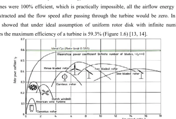
1.5.4. Betz limit
An important operational characteristic of wind turbines is the Betz limit. It indicates the theoretical maximum possible energy that the turbine can extract from the wind. If turbines were 100% efficient, which is practically impossible, all the airflow energy would be extracted and the flow speed after passing through the turbine would be zero. In 1928, Betz showed that under ideal assumption of uniform rotor disk with infinite number of blades the maximum efficiency of a turbine is 59.3% (Figure 1.6) [13, 14].
9
1.5.5. Upwind and downwind turbines
As shown in Figure 1.7 the upwind configuration, the turbine faces into the wind with the blades in front of the nacelle, whereas a downwind turbine has its blades to the rear of the nacelle and faces away from the wind. An upwind turbine produces a higher power than that in the downwind configuration, because it eliminates the tower shadow on the blades. This results in lower noise, lower blade fatigue, and smoother power output. However, a drawback is that the turbine must constantly be turned into the direction of wind by the yaw mechanism. The heavier yaw mechanism of an upwind turbine requires a heavy duty and stiffer rotor compared to a downwind configuration. In contrast, the downwind turbine has the wind shade of the tower in the front and loses some power from the slight wind drop.
Figure 1.6: (a) Upwind structure (b) Downwind structure [12].
However, it allows the use of a free yaw system. It also allows the blades to deflect away from the tower when loaded. Its drawback is that the turbine may yaw in the same direction for a long period of time, which can twist the cables that carry current from the nacelle. Both types have been used in the past. Although, the upwind turbine configuration has become more common [15].
1.6. Wind energy conversion
In this section, properties of the wind, which are of interest in this report, will be described. First the wind distribution, i.e., the probability of a certain average wind speed, will be presented. The wind distribution can be used to determine the expected value of certain quantities, e.g. produced power. Then different methods to control the aerodynamic power will be described.
10
1.6.1. Aerodynamic power control
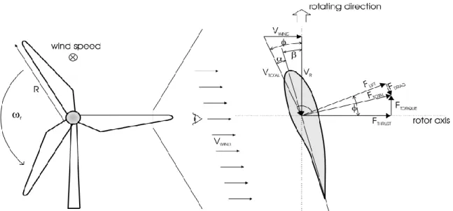
Figure 1.7: Aerodynamic forces and velocities at a rotor blade.
There are two methods to limit the aerodynamic conversion at high wind speed. Pitch control which turn the blades out of the wind and stall control, where the blades lose their aerodynamic efficiency at high wind speeds. The amount of energy that is extracted from wind and converted into mechanical energy is depending on the radial force acting on the blade. The formation of the force depends on particular prof ile design and dimension and is shown in Figure 1.9. The Cp(λ, β) characteristic gives us a power coefficient, that depends on the tip speed ratio λ and the pitch angle β. For blade profiles two forces are generally used to describe the characteristics, lift force component (Flift) and a drag component (Fdrag) which
resulting as Ftotal. The Flift component and an Fdrag together are transformed into a pair of
axial Fthrust force and rotor’s directions Ftorque components, where only the Ftorque produces the driving torque around the rotor shaft. By varying the pitch angle, β the size the direction of Ftotal components can be changed. The axial forces Fthrust has no driving effect but puts
stress on rotor blades and furthermore, leads to a thrust on the nacelle and on tower [19].
1.6.1.1. Pitch control
In this method there is a mechanism to physically turn the blades around their longitudinal axes. At low wind speed a control system will use this feature to maximise energy extracted from the wind. During the higher wind speed the torque or power can easily be limited to its rated value by adjusting the pitch angle β. In addition the axial aerodynamics forces are reduced. This method is almost always used with variable speed turbines in order to make operation at high wind speed possible and safety.
11
Figure 1.8: Calculated Cp(λ, β) surface base on real data blade[19].
On a pitch controlled wind turbine the turbine´s electronic controller checks the power output of the turbine constantly. When the power output becomes too high, it requested the blade pitch mechanism to immediately turn the blades slightly out of the wind. When the wind speed is less strong the blades are turned back, into the most effective position [19].
1.6.1.2. Passive stall regulation
Passive stall controlled wind turbines have the rotor firmly attached to the hub at a fixed angle. Accordingly, using the passive stall method the pitch angle β is always constant, no mechanism to turn the blades around their axes is necessary. The blades are aerodynamically designed to stall at higher wind speeds, and the incoming power is limited close to the rated. When the wind speed increases, the angle α, which is the angle of attack, will increase. Above a certain angle α, the stall effect occur, the torque producing force can be limited approximately to its rated value. This concept is used for around 60% of the constant speed wind turbine in the world [19].
12
Figure 1.9: Effect for different pitch angles with constant speed operation [19].
Advantages of the stall control system are that moving parts in the rotor blades are avoided and a complex control system is not necessary. On the other hand, stall control involves a very complex aerodynamic design and related design challenges in the structural dynamics of the whole wind turbine, for instance to avoid stall induced vibrations.
A normal passive stall controlled wind turbine usually have a drop in the electrical power output for higher wind speeds, as the rotor blades go into deeper stall, which is a drawback. For fixed speed operation, an advantage is that stall control gives lower power pulsation compared to pitch control [20].
1.6.1.3. Active stall regulation
The active stall regulation offers both, the advantages of pitch controlled blades and the stall effect. Due to the pitch controlled blades, one of the advantages of active stall is that one can control the power output more accurately than with passive stall, so that the average power is always at the rated value at wind speed above rated. As with pitch control it is largely an economic question whether it is worth to pay for the added complexity of the machine, when the blade pitch mechanism is added.
13
Besides providing power control, the blade pitch system is also used to accelerate the blades from idling to operational speed and bringing the rotor back to a safe idling situation in case of a grid loss or any other functional error.
The rotor blades are able to be pitched like the pitch controlled wind turbines. The difference is that when the machine reaches its rated power, the blades will pitch in the opposite direction, increasing their angle to the wind and going into a deeper stall.
The active stall control system is often installed in the large fixed speed turbines (1 MW and more) [19].
1.7. Wind energy conversion system configurations
The wind turbine is one of the most important elements in wind energy conversion systems. Over the years, different types of wind turbines have been developed [24]. This section provides an overview of wind turbine technologies, including fixed and variable speed turbines.
A fundamental concept in understanding wind technology is wind energy capture. Wind holds in it a discrete amount of power at any given point in time, dependent in large part on the wind speed. As wind speed can vary greatly, wind turbines must be capable of operating over a wide wind speed range. The wind turbine can operate in one of two ways either fixed speed or variable speed. For fixed speed wind turbines, the generator (induction generator) is directly connected to the grid. Since the speed is almost fixed to the grid frequency, and most certainly not controllable, it is not possible to store the turbulence of the wind in form of rotational energy. Therefore, for a fixed-speed system the turbulence of the wind will result in power variations, and thus affect the power quality of the grid [25]. For a variable speed wind turbine the generator is controlled by power electronic equipment, which makes it possible to control the rotor speed. In this way the power fluctuations caused by wind variations can be more or less absorbed by changing the rotor speed [26] and thus power variations originating from the wind conversion and the drive train can be reduced. Hence, the power quality impact caused by the wind turbine can be improved compared to a fixed speed turbine [27].
The generator and power converter in a wind energy conversion system are the two main electrical components. Different designs and combinations of these two components lead to a wide variety of WECS configurations [24], which can be classified into three groups:
(1) Fixed speed WECS without power converter interface, (2) WECS using reduced capacity converters, and
14
In this section the above wind turbine systems will be presented:
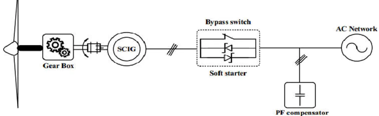
1.7.1. Fixed speed wind turbine
A typical configuration of WECS without a power converter interface is illustrated in Figure 1.15, where the generator is connected to the grid through a transformer. A squirrel cage induction generator (SCIG) is exclusively used in this type of WECS, and its rotational speed is determined by the grid frequency and the number of poles of the stator winding. For a four-pole megawatt generator connected to a grid, the generator operates at a speed slightly higher than 1800 rpm. At different wind speeds, the generator speed varies within 1% of its rated speed. A gearbox is normally required to match the speed difference between the turbine and generator such that the generator can deliver its rated power at the rated wind speed. This configuration requires a soft starter to limit high inrush currents during system start up, but the soft starter is by passed by a switch after the system is started. During normal operation, the system does not need any power converter. A three phase capacitor bank is usually required to compensate for the reactive power drawn by the induction generator.
Figure 1.11: Wind energy conversion system without power converter interface. This wind energy system features simplicity, low manufacturing, maintenance costs, and reliable operation. The main drawbacks include: (1) the system delivers the rated power to the grid only at a given wind speed, leading to low energy conversion efficiency at other wind speeds; and (2) the power delivered to the grid fluctuates with the wind speed, causing disturbances to the grid. Despite its disadvantages, this wind energy system is still widely accepted in industry with a power rating up to a couple of megawatts.
1.7.2. Variable speed wind turbine with reduced capacity converters
Variable speed operation has a series of advantages over fixed speed wind systems. It increases the energy conversion efficiency and reduces mechanical stress caused by wind gusts. The latter has a positive impact on the design of the structure and mechanical parts of the turbine and enables the construction of larger wind turbines. It also reduces the wear and
15
tear on the gearbox and bearings, expanding the life cycle and reducing the maintenance requirements. The main drawback of variable speed WECS is the need for a power converter interface to control the generator speed, which adds cost and complexity to the system. However, the power converter decouples the generator from the grid, which enables the control of the grid-side active and reactive power [28]. Variable speed WECS can be further divided into two types based on the power rating of the converter with respect to the total power of the system: reduced capacity power converter and full capacity power converter. The variable speed WECS with reduced capacity converters are only feasible with wound rotor induction generators (WRIG) since variable speed operation can be achieved by controlling the rotor currents without the need to process the total power of the system. There are two designs for the WRIG configurations: one with a converter controlled variable resistance, and the other with a four quadrant power converter system.
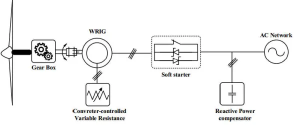
1.7.2.1. Wound rotor induction generator with variable rotor resistance
Figure 1.16 shows a typical block diagram of the WRIG wind energy system with a variable resistance in the rotor circuit. The change in the rotor resistance affects on the torque and speed characteristics of the generator, enabling variable speed operation of the turbine. The rotor resistance is normally made adjustable by a power converter. The speed adjustment range is typically limited to about 10% above the synchronous speed of the generator [29]. With variable speed operation, the system can capture more power from the wind, but also has energy losses in the rotor resistance. This configuration also requires a soft starter and reactive power compensation. The WRIG with variable rotor resistance has been in the market since the mid 1990s with a power rating up to a couple of megawatts.
16
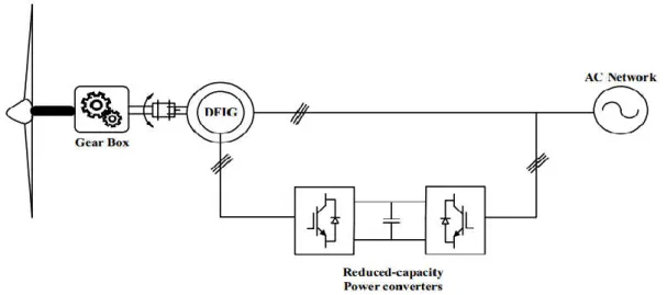
1.7.2.2. Doubly fed induction generator with rotor converter
A typical block diagram of the doubly fed induction generator (DFIG) wind energy system is shown in figure 1.17. The configuration of this system is the same as that of the WRIG system except that (1) the variable resistance in the rotor circuit is replaced by a grid connected power converter system, and (2) there is no need for the soft starter or reactive power compensation. The power factor of the system can be adjusted by the power converters. The converters only have to process the slip power in the rotor circuits, which is approximately 30% of the rated power of the generator, resulting in reduced converter cost in comparison to the wind energy systems using full capacity converters [28].
Figure 1.13: Variable speed configuration with reduced capacity converters.
The use of the converters also allows bidirectional power flow in the rotor circuit and increases the speed range of the generator. This system features improved overall power conversion efficiency, extended generator speed range (±30%), and enhanced dynamic performance as compared to the fixed speed WECS and the variable resistance configuration. These features have made the DFIG wind energy system widely accepted in today's market.
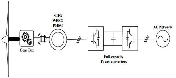
1.7.3. Variable speed wind turbine with full capacity power converters
The performance of the wind energy system can be greatly enhanced with the use of a full capacity power converter. Figure 1.18 shows such a system in which the generator is connected to the grid via a full capacity converter system [28]. Squirrel cage induction generators, wound rotor synchronous generators, and permanent magnet synchronous generators (PMSG) have all found applications in this type of configuration with a power rating up to several megawatts. The power rating of the converter is normally the same as that of the generator. With the use of the power converter, the generator is fully decoupled from the grid, and can operate in full speed range.
17
Figure 1.14: Variable speed configurations with full capacity converters.
This also enables the system to perform reactive power compensation and smooth the grid connection. The main drawback is a more complex system with increased costs. It is noted that the wind energy system can operate without the need for a gearbox if a low speed synchronous generator with a large number of poles is used. The elimination of the gearbox improves the efficiency of the system and reduces initial costs and maintenance. However, a low speed generator has a substantially larger diameter to accommodate the large number of poles on the perimeter, which may lead to an increase in generator and installation costs.
1.8. Advantages and disadvantages of wind energy
Let’s discuss advantages and disadvantages of wind energy
1.8.1. Advantages of wind energy
Wind Energy is an inexhaustible source of energy and is virtually a limitless resource. Energy is generated without polluting environment.
This source of energy has tremendous potential to generate energy on large scale. Like solar energy and hydropower, wind power taps a natural physical resource. Windmill generators don’t emit any emissions that can lead to acid rain or greenhouse
effect.
Wind Energy can be used directly as mechanical energy.
In remote areas, wind turbines can be used as great resource to generate energy. In combination with solar energy they can be used to provide reliable as well as steady
18
Land around wind turbines can be used for other uses, e.g. Farming.
1.8.2. Disadvantages of wind energy
Wind energy requires expensive storage during peak production time. It is unreliable energy source as winds are uncertain and unpredictable. There is visual and aesthetic impact on region.
Requires large open areas for setting up wind farms.
Noise pollution problem is usually associated with wind mills.
Wind energy can be harnessed only in those areas where wind is strong enough and weather is windy for most parts of the year.
Usually places, where wind power set up is situated, are away from the places where demand of electricity is there. Transmission from such places increases cost of electricity.
The average efficiency of wind turbine is very less as compared to fossil fuel power plants. We might require many wind turbines to produce similar impact.
It can be a threat to wildlife. Birds do get killed or injured when they fly into turbines. Maintenance cost of wind turbines is high as they have mechanical parts which
undergo wear and tear over the time.
Even though there are advantages of wind energy, the limitations make it extremely difficult for it to be harnessed and prove to be a setback [30].
1.9. Conclusion
This chapter provided an overview of wind energy conversion systems. The basic concepts of wind power, aerodynamic conversion, aerodynamic control, facts, current state, and market trends of wind power technology were presented. The fundamentals of wind energy systems were discussed, including fixed and variable speed operations which complement the in depth analysis of wind energy systems covered in the other chapters of this report.
19
2.1. Introduction
This chapter has the objective to put in evidence the doubly fed induction machine, in order to study its principle of working and the value of advantages and performances brought by this machine, as well as the different domains of application.
In addition, to present the modeling of DFIG, this modeling was based on the development of equivalent diagrams drifted of the theory of the rotating field. The simplicity of conception and maintenance of this machine to the favor of the industries, come however with a big physical complexity, as well as the vector control.
2.2. Components of DFIG
DFIG, as mentioned earlier, is basically a conventional wound rotor induction machine in which the stator is directly connected to the grid through a transformer, and the connection of the rotor to the stator (and grid) is via a back to back voltage source convertor. The rotor converter system consists of a grid side converter (GSC) and rotor side converter (RSC) connected via a DC link. A simplified schematic diagram of a DFIG based wind energy generation system is shown in figure 2.1.
Figure 2.1: DFIG based wind Energy conversion system scheme.
The generator is called DFIG because the power is fed from both stator and the rotor circuits to the grid. The rotor circuit handles typically about 25-30% of the generator rated power, this percentage allows the DFIG to have about 30% operational speed range around the synchronous speed and reduces the rating and the cost of the rotor converter [31, 32]. The size of the converter is not related to the total generator power but to the selected speed range and, hence, to the “slip” power, thus the cost of the converter increases when the speed range becomes wider. The selection of the speed range, therefore, is based on the economic optimisation of investment costs and on increased efficiency. Since the DFIG is connected to the grid, the high transient currents due to the grid disturbances may destroy the power
20
electronic devices of the rotor converter. A protection system called “crowbars” are being used in which the rotor winding can be short circuited during the fault period via a small resistance and released when the fault is cleared.
2.3. Principle of Operation of DFIG
Large doubly fed electric machines in the industry are three phase wound rotor type. Although their principles of operation have been known for decades, the massive application has only recently entered and is almost exclusively due to the advent of wind power technologies. The DFIG operates in both sub-synchronous (rotor speed lower than synchronous speed) and super-synchronous (rotor speed higher than synchronous speed) modes which allows an operational speed range of about 30% around the synchronous speed.
The main advantage of doubly fed induction generator when used in wind turbines is that it has the ability to maintain the amplitude and the frequency of the output voltage essentially constant at grid values, no matter the speed of the wind turbine rotor. Because of this, doubly fed induction generator can be directly connected to the AC power network and remain synchronised at all times. Other advantages include the ability to control reactive power from the rotor circuits to the grid, which enables the DFIG to support the voltage stability and power factor correction at the point of common coupling (PCC).
The feature of controlling the rotor speed to overcome the wind speed variation is done by adjusting the frequency of the AC voltages and currents fed to the rotor windings. This principle can be understood by explaining the sub-synchronous and super-synchronous modes of operation discussed below.
2.3.1. Sub-synchronous mode of operation
When the rotor speed of the generator nrotor is below the synchronous speed ns the rotor
frequency frotor of the voltage induced increases accordingly and (according to the normal
convention) is of positive polarity. This positive polarity means that the phase sequence of the AC currents injected into the generator rotor windings will make the rotor magnetic field rotate in the same direction as the generator rotor, and as a result of controlling the phase sequence of injected current the rotor “receives” power from the grid through the rotor converters (GSC and RSC). This approach to control the power flow in the rotor winding of DFIG in the sub-synchronous mode can be explained by understanding the power flow equations of an induction machine, as explained below [33, 34].
21
Pg is the air gap power, Pm is the mechanical power transferred between the rotor and the shaft, and Pr is the “slip” power (sPg) that is transferred between the rotor converters and the electrical grid in the case of DFIG. The slip “s” is defined by:
s r s s
(2-1) The conventional induction motor with short circuited rotor windings runs at a speed lower than its synchronous speed. The mechanical power Pm is considered positive when transferred from the rotor to the shaft and then driving the mechanical load (like pump or fan). In this case the slip is positive (0 < s < 1), the air gap power that is transferred from the stator to the rotor will be positive. If the direction of flow for both Pg and Pm is reversed (i.e. Pg and Pm
have negative values) the machine will operate in the generator mode (DFIG in sub-synchronous mode). The slip power Pr will also be negative and will be supplied by the converters (RSC and GSC) to the rotor in which the rotor-side converter (RSC) operates as an inverter and the grid side converter (GSC) as a rectifier. The reversion of the slip power direction in the rotor circuit is done by reversing the phase sequence of the AC voltage or current that is injected into the rotor winding of the DFIG. Figure 2.2 shows the slip power flow directions of the DFIG in both sub-synchronous (grid to rotor) and super-synchronous (rotor to grid) modes.
Figure 2.2: Active power flows in the DFIG during sub-synchronous operation.
2.3.2. Super-synchronous mode of operation
Similarly, when the generator rotor speed nrotor increases above the synchronous speed nS, the frequency frotor of the ac currents that need to be fed into the generator rotor windings
increases accordingly and is of negative polarity now.
Generator
Stator
Rotor
Power22
The negative polarity of the frequency frotor indicates that the phase sequence of the three
phase AC currents fed into the rotor windings must make the rotor magnetic field rotate in the direction opposite to that of the generator rotor. This means that above the synchronous speed the slip (s) is negative (s < 0), the DFIG operates in the super-synchronous mode, where the slip power Pr is controlled by controlling the phase sequence of the injected currents to the rotor windings of the DFIG. In this mode, the slip power will be positive and transferred from the generator rotor to the grid through the rotor converters of the DFIG, where the RSC operates as a rectifier and the GSC as an inverter.
Figure 2.3:Active power flow in the DFIG during super-synchronous operation.
2.4. Advantages and disadvantages of the DFIG
We introduce in this paragraph some of the advantages and the drawbacks of DFIG
2.4.1. Advantages of the DFIG
The DFIG is having lot of advantages than the other types such as FSIG, VSIG and PMSG. Some of the advantages of DFIG are given below.
It has the ability of decoupling the control of the active and reactive power by controlling the rotor terminal voltages. Hence, the power factor control can be implemented in this system.
The DFIG is usually a wound rotor induction generator, which is simple in construction and cheaper than a PMSG.
In a DFIG based wind turbine generator system, the power rating of the power converters is typically rated ±30% around the rated power. This characteristic leads to many merits, such as reduced converter cost, reduced filter volume and cost, less switching losses, less harmonic injections into the connected grid. Improved overall
Generator
Stator
Rotor
Power23
efficiency (approx. 2-3% more than full scale frequency converter) if only the generator and power converters are considered.
Aerodynamic, gearbox and converter losses of the DFIG are less.
2.4.2. Disadvantages of the DFIG
The major drawbacks of DFIG are specified below:
Needs slip rings also it requires frequent maintenance.
Has limited fault ride through capability and needs protection schemes. Have complex control schemes.
2.5. Modeling of DFIG
The modeling of electrical machines consists in the elaboration of mathematical models which make it possible to predict the behavior of the machine in different operating modes, thus anticipating the points which are likely to cause disturbances.
2.5.1. Simplifying assumptions
The asynchronous machine comprises a winding distribution and a very complex geometry. Therefore, for analysis taking into account its exact configuration, the following assumptions have been made for this detailed model [35]:
The machine is symmetrical, The skin effect is neglected, Iron losses are neglected,
Magnetic saturation is neglected.
2.5.2. Mathematical model of doubly fed induction generator
2.5.2.1. Electrical equation of DFIG
In the preceding conditions the equations in matrix form are written: For the stator:
cs bs as s s s cs bs as cs bs as I I I R R R dt d V V V 0 0 0 0 0 0 (2-2)
24 cr br ar r r r cr br ar cr br ar I I I R R R dt d V V V 0 0 0 0 0 0 (2-3)
2.5.2.2. Magnetic equations
The stator and rotor fluxes equations in matrix form are given by the following expressions:
s Lss .is Msr
.ir (2-4)
r Lrr .ir Msr
.is (2-5) Where:
s s s s s s s s s ss l M M M l M M M l L
r r r r r r r r r rr l M M M l M M M l L And
cos ) 3 2 cos( ) 3 4 cos( ) 3 4 cos( cos ) 3 2 cos( ) 3 4 cos( ) 3 2 cos( cos M M Msr sr tWhere M represents the maximum value of the Stator-Rotor mutual inductance coefficients obtained when the windings are opposite one another.
By replacing relations (2-4) and (2-5) respectively in relations (2-2) and (2-3), we obtain the following two expressions:
) . ( . s ss s sr r s s M i dt d i dt d L i R V (2-6)
) . ( . r rr r sr t s r r M i dt d i dt d L i R V (2-7) Where:
; sc sb sa s V V V V
; rc rb ra r V V V V
; sc sb sa s i i i i
; rc rb ra r i i i i
; sc sb sa s
rc rb ra r
; 0 0 0 0 0 0 s s s s R R R R
r r r r R R R R 0 0 0 0 0 025
2.5.2.3. Mechanical equation
The mechanical equation of the machine is described in the form:
T T f. dt d J e r (2-8)
This equation leads to differential equations with variable coefficients (2-6) and (2-7). Also the analytical study of the behavior of the system is relatively laborious considering the large number of variables. Then mathematical transformations are used to describe the behavior of the machine using differential equations with constant coefficients.
2.5.3. Doubly fed induction generator model (d-q Model)
The d-q dynamic model of DFIG would be very beneficial in terms of studying the behavior under sub-synchronous and super-synchronous modes of operation and applying the vector control approach to control the output active and reactive power. This model is used to implement vector control in order to control the output active power of the DFIG [36].
2.5.3.1. Park transformation
The transformations is used to convert the three phase magnitudes into two phase magnitudes and is performed in the stationary frame, Figure 2.4 representing the quantity in another reference frame, by projecting the vector on the two orthogonal axes of the new frame, where the d-axis of the excitation frame is aligned with the stator flux.
Figure 2.4: PARK model of DFIG.
The asynchronous machine is a strong coupled machine, therefore its representation in the three phase system is particularly complex. For better behavior of an asynchronous machine, it is necessary to use a precise and sufficiently simple model. Then the two axis d-q model given by the Park transformation is used. The new model is obtained by multiplying the
26
equations of fluxes and tensions by the Park matrix which is expressed by [38]:
[ ( )] = ⎣ ⎢ ⎢ ⎢ ⎡ cos − 2 3 cos ( −4 3 − − sin − 2 3 − sin ( −4 3) √ √ √ ⎦ ⎥ ⎥ ⎥ ⎤ (2-9)
It is noted in figure 2.5 that θs and θr are the angle of the Park transformation of stator and rotor magnitudes respectively.
The transformation of Park leads to a relation linking the angles θs and θr, which expresses by:
s
r
Figure 2.5: Representation of the machine in the two-phase frame.
2.5.3.2. Voltages equation
We apply Park's transformation to expression (2-2) and multiplying the two members of equality by [P(s)] and simplifying, we will have:
sdq
s
sdq
sdq
s s
sdq
P dt d P dt d i R V [ ( )] [ 1( )] (2-10) Then the expression (2-10) becomes: qs ds s s qs ds qs ds s s qs ds dt d dt d dt d i i R R V V 0 0 0 0 (2-11)
Similarly, by the same steps we obtain the rotor expression as the following:
qr dr r r qr dr qr dr r r qr dr dt d dt d dt d i i R R V V 0 0 0 0 (2-12) We write:
27
ds s qs qs s qs qs s ds ds s ds dt d i R V dt d i R V (2-13) By analogy, the following voltages are obtained for the rotor quantities:
dr s qr qr r qr qr s dr dr r dr dt d i R V dt d i R V ) ( ) ( (2-14) With: s s r s s s r dt d dt d ;2.5.3.3. Flux equation
The flux matrix system is written in the following form:
For the stator:
qr dr m m qs ds s s qs ds i i L L i i L L 0 0 0 0 (2-15) For the rotor:
qs ds m m qr dr r r qr dr i i L L i i L L 0 0 0 0
(2-16)
Where the cyclic inductances:
Ls ls Msr;Lm Msr
2 3
andLr lr Mrs
2.5.3.4. Electromagnetic torque equation
After the change of variable, the expression of the electromagnetic torque can be expressed in different forms, one finds this one [38]:
T = p ѱ i − ѱ i (2-17)
T = p. M i . i − i . i (2-18)
T = . ѱ . i − ѱ . i (2-19)
![Figure 1.2: Global cumulative wind power capacities from 2001 to 2020 [4].](https://thumb-eu.123doks.com/thumbv2/123doknet/12257510.320542/17.892.183.755.719.1058/figure-global-cumulative-wind-power-capacities.webp)
![Figure 1.3: Inside of a Wind Turbine [8].](https://thumb-eu.123doks.com/thumbv2/123doknet/12257510.320542/18.892.204.736.755.1123/figure-inside-wind-turbine.webp)
![Figure 1.8: Calculated C p (λ, β) surface base on real data blade[19].](https://thumb-eu.123doks.com/thumbv2/123doknet/12257510.320542/24.892.140.746.111.581/figure-calculated-λ-surface-base-real-data-blade.webp)
![Figure 1.9: Effect for different pitch angles with constant speed operation [19].](https://thumb-eu.123doks.com/thumbv2/123doknet/12257510.320542/25.892.301.640.116.341/figure-effect-different-pitch-angles-constant-speed-operation.webp)