HAL Id: hal-00920916
https://hal.archives-ouvertes.fr/hal-00920916
Submitted on 19 Dec 2013
HAL is a multi-disciplinary open access archive for the deposit and dissemination of sci-entific research documents, whether they are pub-lished or not. The documents may come from
L’archive ouverte pluridisciplinaire HAL, est destinée au dépôt et à la diffusion de documents scientifiques de niveau recherche, publiés ou non, émanant des établissements d’enseignement et de
Analyzing the benefit of optical transmission systems
based on Root Raised Cosine PS-QPSK and a flexible
channel grid
Aida Seck, Petros Ramantanis, Jordi Vuong, Djalal Falih Bendimerad,
Catherine Lepers, Badr-Eddine Benkelfat, Yann Frignac
To cite this version:
Aida Seck, Petros Ramantanis, Jordi Vuong, Djalal Falih Bendimerad, Catherine Lepers, et al.. Ana-lyzing the benefit of optical transmission systems based on Root Raised Cosine PS-QPSK and a flexible channel grid. Optics Express, Optical Society of America - OSA Publishing, 2013, 21, pp.10496-10501. �hal-00920916�
Analyzing the benefit of optical transmission
systems based on Root Raised Cosine PS-QPSK
and a flexible channel grid
A. Seck, P. Ramantanis, J. Vuong, D. F. Bendimerad, C. Lepers, B.-E. Benkelfat, and Y. Frignac*
Institut Mines-Télécom/Télécom SudParis, CNRS UMR 5157 SAMOVAR, 9 rue Charles Fourier, 91011 EVRY, France
*yann.frignac@telecom-sudparis.eu
Abstract: We numerically investigate the multi-channel transmission performance of Polarization Switched Quadrature Phase Shift Keying (PS-QPSK) and we compare it to the performance of Polarization-Division-Multiplexed QPSK (PDM-QPSK), using Root Raised Cosine (RRC) spectral shaping, in the context of a flexible channel grid. We point out the impact of the roll-off factor and the potential influence of different dispersion compensation scenarios. Finally, the advantage of PS-QPSK against PDM-QPSK is presented as a function of the system parameters, while we also discuss the benefit of a RRC spectral shaping against a tight filtering at the transmitter side with a 2nd order super-Gaussian-shaped filter.
©2013 Optical Society of America
OCIS codes: (060.1660) Coherent communications; (060.2330) Fiber optics communications. References and links
1. M. Karlsson and E. Agrell, “Which is the most power-efficient modulation format in optical links?” Opt. Express 17(13), 10814–10819 (2009).
2. C. Behrens, D. Lavery, D. S. Millar, S. Makovejs, B. C. Thomsen, R. I. Killey, S. J. Savory, and P. Bayvel, “Ultra-long-haul transmission of 7×42.9 Gbit/s PS-QPSK and PDM-BPSK,” Opt. Express 19(26), B581–B586 (2011).
3. P. Serena, A. Vannucci, and A. Bononi, “The performance of polarization switched-QPSK (PS-QPSK) in dispersion managed WDM transmissions,” in Proc. of ECOC p. Th.10.E.2 (2010).
4. M. Sjödin, B. J. Puttnam, P. Johannisson, S. Shinada, N. Wada, P. A. Andrekson, and M. Karlsson,
“Transmission of PM-QPSK and PS-QPSK with different fiber span lengths,” Opt. Express 20(7), 7544–7554 (2012).
5. P. Poggiolini, G. Bosco, A. Carena, V. Curri, and F. Forghieri, “Performance evaluation of coherent WDM PS-QPSK (HEXA) accounting for non-linear fiber propagation effects,” Opt. Express 18(11), 11360–11371 (2010). 6. B. Krongold, T. Pfau, N. Kaneda, and S. C. J. Lee, “Comparison between PS-QPSK and PDM-QPSK with equal
rate and bandwidth,” IEEE Photon. Technol. Lett. 24(3), 203–205 (2012).
7. G. Bosco, “Spectral shaping in ultra-dense WDM systems: optical vs. electrical approaches,” in Proc. of OFC, OM3H.1 (2012).
8. P. Ramantanis, A. Seck, J. Vuong, D. Bendimerad, and Y. Frignac, “Spectral shaping tradeoffs in root-raised-cosine PDM-QPSK nonlinear transmission,” in Proc. of ECOC, P04.01 (2012).
9. J. Fickers, A. Ghazisaeidi, M. Salsi, G. Charlet, F. Horlin, P. Emplit, and S. Bigo, “Design rules for pulse shaping in PDM-QPSK and PDM-16QAM nyquist-WDM coherent optical transmission systems,” in Proc. of ECOC, p. We.1.C.2 (2012).
10. B. Châtelain, C. Laperle, K. Roberts, M. Chagnon, X. Xu, A. Borowiec, F. Gagnon, and D. V. Plant, “A family of nyquist pulses for coherent optical communications,” Opt. Express 20(8), 8397–8416 (2012).
11. R. I. Killey, H. J. Thiele, V. Mikhailov, and P. Bayvel, “Reduction of intrachannel nonlinear distortion in 40 Gb/s-based WDM transmission over standard fiber,” IEEE Photon. Technol. Lett. 12(12), 1624–1626 (2000). 12. G. P. Agrawal, Lightwave Technology Telecommunication Systems (John Wiley & Sons, Inc, 2005). 13. P. Johannisson, M. Sjödin, M. Karlsson, H. Wymeersch, E. Agrell, and P. A. Andrekson, “Modified constant
14. A. Seck, P. Ramantanis, J. Vuong, D. F. Bendimerad, C. Lepers, and Y. Frignac, “ Novel carrier phase estimation scheme for polarization switched-QPSK-based transmission systems,” in Proc. of OFC, OTu3I. (2013).
15. P. Serena, M. Salsi, M. Bertolini, A. Vannucci, N. Rossi, and F. Vacondio, Optilux Toolbox,
http://optilux.sourceforge.net 1. Introduction
In the context of coherent optical communications, the potential of several multi-level modulation formats has been extensively investigated. As shown in [1], PS-QPSK appears as the most power efficient modulation format, while several numerical and experimental investigations have demonstrated its high resistance to non-linear effects [2–5]. Nevertheless, since PS-QPSK may be seen as a coded version of PDM-QPSK [6], the increased minimum distance between symbols comes at the price of a reduced Information Spectral Density (ISD). On the other hand, the ever-increasing demand for spectrally efficient transmission has paved the way towards a channel spacing below the “standard” 50 GHz, while at the same time, network considerations introduce the need for a flexible channel grid. Finally, techniques based on spectral shaping [7] such as Root Raised Cosine (RRC) filtering [8–10] have also been employed in order to further increase the ISD of optical transmission systems.
In this paper, by performing vast numerical simulations, we investigate the possible advantage of using RRC spectral shaping together with PS-QPSK, comparing this solution against previous options being either PDM-QPSK with the same spectral shaping [8,9] or PS-QPSK with a rough optical filtering at the transmitter side [5]. Fixing the symbol rate at 32 Gbaud, our objective is to quantify the overall gain of this solution in terms of transmission quality, exploring Nyquist or non-Nyquist WDM configurations and a variable channel grid. Having in mind that the fiber nonlinear degradations may particularly affect PS-QPSK using RRC spectral shaping, we also assess dispersion compensation (DC) schemes, with or without in-line dispersion compensation. After a quick introduction to our system simulation setup in section 2, in section 3 we present our simulation results for RRC-PS-QPSK, while also optimizing the roll-off factor depending on the considered system configuration. Finally, in section 4, in an attempt to position RRC-PS-QPSK with respect to existing solutions, we first compare it against PS-QPSK with tight filtering at the transmitter side and the two corresponding PDM-QPSK solutions, while we also quantify the RRC-spectral shaping gain over filtering and the coding gain of PS-QPSK over equivalent PDM-QPSK solutions for the studied spectral shaping techniques. Our numerical results indicate that RRC-PS-QPSK outperforms RRC-PDM-QPSK in terms of transmission performance.
2. Simulation setup
The simulation setup is shown in Fig. 1. The transmitter generates 1 or 9 signals with a symbol rate R of 32 Gbaud, based on a modulation format that is either filtered NRZ-PS-QPSK (referred to as “fNRZ_PS” in the following) using Non Return to Zero (NRZ) pulses with a 20% raised time or RRC-PS-QPSK (referred to as “RRC_PS”). The PS-QPSK modulation is obtained following the scheme represented in [1] and based on a PDM-QPSK transmitter. For each channel, b1, b2 and b3 are derived from different random sequences of Ns = 4096 symbols while b4 = xor{xor(b1, b2), b3}. The channels are multiplexed using a frequency spacing Δν of 32, 36, 40 or 50 GHz with no time decorrelation and the same States Of Polarization (SOPs). Filtering is considered before multiplexing in the “fNRZ_PS” case by using a usual 2nd order super-gaussian optical filter with a variable 3 dB Bandwidth W, within the range {25-64} GHz. Similarly, in the “RRC_PS” case, a signal with a RRC spectral shape was generated for each of the 9 channels (as shown in Fig. 1), with roll-off factors ρ within the range {0-1}. In our simulations the signal complex envelopes for the two PDM tributaries Ax and Ay are numerically represented by Nt = 64 samples per symbol, achieving a total of Nfft = 4096x64 samples. For the generation of the transmitted pulses in the RRC spectral shaping case, we do not take into account potential imperfections caused by
either non-ideal optical filtering or limited resolution of Digital-To-Analog Converters [7]. We also indicate in Fig. 1 (as it is well-known for RRC signals) that higher values of ρ lead to narrower pulse widths and larger spectral occupancies.
The transmission line is composed of 20 spans of 100km considering noiseless in-line Erbium Doped Fiber Amplifiers and a fiber with an attenuation coefficient α = 0.2 dB⋅km−1
, a nonlinear coefficient γ = 1.31 W−1⋅km−1, a Chromatic dispersion parameter D = 20 ps⋅nm−1⋅km−1 and an effective area Aeff = 80 µm2
. We consider that the average power per channel over the two PDM tributaries (noted as Pin,avg in the following) at the beginning of each span is the same. Chromatic dispersion is fully compensated using dispersion compensating fibers (DCFs) with D equal to −100 ps⋅nm−1.km−1, either at the end of each span (a DC scenario noted as “wDCF” in the following) or only at the end of the link (referred to as “w/oDCF”). DCFs were considered as linear in all cases, whereas the pre-compensation was optimized for all the scenarios. The values of pre-pre-compensation used in our simulations (−200 ps⋅nm−1 and −20200 ps.nm−1 for the cases “wDCF” and “w/oDCF” respectively are close to the values reported in [11]. Fiber propagation is emulated using the Split Step Fourier Method, based on the Coupled Nonlinear Schrödinger Equation [12], without taking into account Polarization Mode Dispersion. After propagation, in the case of RRC pulse shaping and filtering for NRZ pulses, the central channel is extracted using the corresponding matched filter to the pulse. A coherent receiver incorporating an idealized monochromatic local oscillator and infinite-bandwidth electrical filters was considered. Polarization recovery was performed using the constant modulus algorithm described in [13] with 13 taps. After a carrier phase recovery based on the Viterbi & Viterbi estimator [14] with optimized taps, a joint decision with minimum Euclidean distance was performed. Finally we estimate the central channel Bit Error Rate (BER) (converted afterwards into Q2 factor) by a Monte Carlo (MC) method, after a noise loading process with an artificial total noise figure NF = 25 dB and 400 counted errors. We note that, while the aforementioned high value of NF is used in order to accelerate the MC process, the conclusions reached in the context of our comparative study should remain approximately valid.
λ
i PBS PS-QPSK Ch. i ch1 ch9 W D M-MUX. EDFA x20 spans SMF b1 b2b3 b4 I Q I Q Spectral Shaping Data Streams : 45° (DCF) RRC-filterCentral channel analysis
Coherent Rx BER Spectral Shaping p( t) 0 1 -3 -1 1 30 t 2.Ts Ts RRC spectral Shaping ρ=0 P(f) [li n ear scale] 0 0.5 1 f R Δν ρ ρ=0.5 ρ=1
Fig. 1. Simulation setup for our transmission system including RRC spectral shaping description. p(t) is the fundamental pulse in the case of RRC spectral shaping.
3. Simulation results on RRC-PS-QPSK
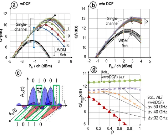
In Figs. 2(a) and 2(b) we show the transmission quality of RRC-PS-QPSK (“RRC_PS” scenario) in terms of Q2 factor as a function of Pin,avg, for both of the dispersion compensation scenarios, i.e. “wDCF” and “w/oDCF” respectively. Each curve corresponds to a different
roll-off factor ρ, in either a single channel or a WDM configuration, for Δν = 50 GHz. For each value of ρ, the highest Q2
value (noted as Q2max) is observed for a power level, referred to in the following as nonlinear threshold (NLT). According to Fig. 2(a), in the single channel configuration, all values of ρ yield approximately the same performance in the linear regime, while increasing ρ improves the Q2
factor in the nonlinear regime. In addition, commenting on the variation of Q2max as a function of ρ, we observe a performance degradation, especially for lower values of ρ. To explain this behavior, we suggest that when applying a RRC spectral shaping with a bandwidth approaching the modulation rate, pulses are spread out the symbol time slot Ts, thus inducing power fluctuations due to Inter-Symbol Interference (ISI) during propagation. This is illustrated in Fig. 2(c) for the signal envelopes on the two polarization tributaries: Ax and Ay. These ISI induced power fluctuations are reduced when increasing ρ. Moreover, the NLT and Q2max increase with ρ, yielding a NLT and Q2
max difference of 2 dB between the best and worst performance in single channel configuration.
Q 2 max (dB) Pin/ ch (dBm) ρ Pin/ ch (dBm) -5 -3 -1 1 3 4 6 8 10 Q 2(dB )
a
ρ 12 WDM 9ch. Single-channel wDCF 0 1 5 0 0.2 0.4 0.6 0.8 8 10 12d
6 1 Δν:32 GHz Δν:40 GHz Δν:50 GHz 1ch., «w/oDCF» NLT 9ch., NLT «w/oDCF»b
ρ WDM 9ch. Single-channel w/o DCF -2 0 1 2 9 10 11 12 14 Q 2(d B) 3 4 5 13 -1 14c
AX (t ) t Ts0 1 0 0 1 :{ }
cn1 0 1 1 0 :{ }
cn Fig. 2. Q2 versus Pin,avg for “RRC_PS” with different roll-off factors for either 1 or 9 channels
(Δν = 50GHz) in the scenarios “wDCF” (a) and “w/oDCF” (b). Illustration of adjacent, spectrally-shaped RRC pulses, in the context of polarization switching (c). Q2
max as a function
of ρ (d) for 1 (solid line) or 9 channels (dashed line) in the case “w/oDCF”.
Furthermore we observe a NLT and Q2max difference of 3 dB and 4 dB respectively between the best performance in WDM and single channel configuration. Nevertheless in the “w/oDCF” scenario (Fig. 2(b)), this difference is reduced to 1 dB for the NLTs and Q2max. The transmission quality difference between single-channel and WDM can be explained by the signal impairments due to cross-nonlinearities between channels, known to be more detrimental for systems with in-line DCFs. In order to analyze the impact of the roll-off factor, we show in Fig. 2(d), the evolution of Q2max as a function of ρ in the scenario
“w/oDCF” for single channel and WDM configuration. We note that the optimal transmission performance in single-channel without DCFs slightly increases with ρ. We also show in Fig. 2(d) the influence of ρ for WDM systems in the scenario “w/oDCF” (appearing with dashed lines), for Δν = 32, 40 or 50 GHz. It turns out that the corresponding Q2
max values as a function of ρ are roughly constant when considering a channel spacing Δν = 50GHz. On the other hand, for Δν = 40 GHz, Q2 remains constant for ρ within the range {0-0.4} and then decreases, while for Δν = 32 GHz, Q2 directly drops for ρ>0. As for each channel the spectral occupancy is higher when increasing ρ, it seems reasonable to attribute these Q2
evolutions to the cross-talk between different channels, appearing when ρ is higher than a given value, with this latter depending on Δν.
4. RRC-PS-QPSK transmission performance comparison
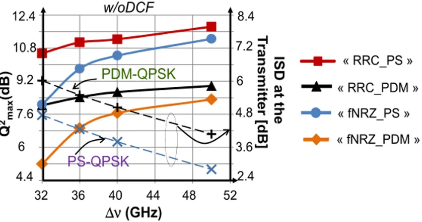
In this section we compare the above-analyzed RRC-PS-QPSK format against the Tx-filtered version of PS-QPSK and the two corresponding PDM-QPSK solutions, with the RRC-PDM-QPSK noted as “RRC_PDM” and the Tx-filtered PDM-RRC-PDM-QPSK noted as “fNRZ_PDM”. In what follows we have optimized ρ, while an optimal filter bandwidth Wopt, found to be roughly about Δν/1.25, was also employed for the “fNRZ_PS” and “fNRZ_PDM” scenarios.
« RRC_PDM » « fNRZ_PS » « fNRZ_PDM » « RRC_PS » Q 2 ma x (d B) 6 7.6 9.2 10.8 4.4 Δν (GHz) 32 36 40 44 48 52 2.4 7.2 3.6 4.8 6 PS-QPSK PDM-QPSK w/oDCF 8.4 12.4 ISD at t he T ra n sm itter [d B ] Fig. 3. Q2
max as a function of the channel spacing Δν in the “w/oDCF” case for all the
considered modulation format solutions.
In Fig. 3 we plot Q2max as a function of Δν, for the DC scheme “w/oDCF”, while we also indicate in the right vertical axis the ISD measured at the transmitter output for both PDM- and PS-QPSK (indicated with dashed lines). According to the results, “RRC_PS” always outperforms “fNRZ_PS”, “fNRZ_PDM” and “RRC_PDM”, while “fNRZ_PDM” always yields the worst performance with a maximum Q2max difference of 5.6 dB with respect to “RRC_PS”. Similar conclusions may be reached when moving to the “wDCF” scenario (not shown here) with the only difference being that the system performance is globally decreased, as it was also discussed in the previous section. Furthermore, for our four configurations, when decreasing the channel spacing from the common 50GHz towards the Nyquist-WDM case 32 GHz, Q2max naturally decreases, while at the same time ISD increases. In order to provide a synthetic comparison between the analyzed solutions, in the following we focus on the quality differences of the curves presented in Fig. 3.
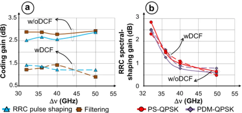
As a first step, analyzing the gain of applying a PS-QPSK coding on PDM-QPSK, in Fig. 4(a) we show their performance difference ΔQ2
max = Q2max(PS-QPSK) - Q2max(PDM-QPSK),
noted as “coding gain”, for either RRC spectral shaping (triangle markers) or Tx-filtering (square markers) and both DC schemes, as a function of Δν. As a second step, in Fig. 4(b) we
show ΔQ2
max between solutions using a RRC spectral shaping against Tx-filtering, noted as “RRC Spectral Shaping gain”.
a 1.5 2.5 3.5 0.5 Δν (GHz) 30 35 40 45 50 55 Co ding ga in (dB) b 1 2 3 0 Δν (GHz) 32 35 40 45 50 55 R R C spec tra l-s h aping ga in (dB)
RRC pulse shaping Filtering PS-QPSK PDM-QPSK w/oDCF
wDCF wDCF
w/oDCF
Fig. 4. “Coding gain” (a) and “RRC spectral shaping gain” (b) as a function of the channel spacing Δν in the “w/oDCF” (solid lines) and in the “wDCF” DC scheme (dashed lines).
Commenting on Fig. 4(a) we note that the “coding gain” is roughly constant as a function of Δν for both DC schemes. Yielding similar performance for both RRC spectral shaping and a Tx-filtering, the “coding gain” is about 2.5dB in the “w/oDCF” case and about 1.5 dB lower for the “wDCF” DC scheme. We may generally conclude that the PS-QPSK coding advantage over PDM-QPSK is not particularly influenced by the channel spacing. Nevertheless, it has to be noted that PS-QPSK coding seems to be more efficient in a system configuration without in-line DCFs. Focusing on Fig. 4(b), we note that for both PDM- and PS-QPSK modulations and both DC schemes, RRC spectral shaping brings a minor improvement of only about 0.5 dB for Δν = 50 GHz, whereas it becomes a particularly profitable option for lower channel spacings, reaching its higher value of about 2.7 dB for Δν = R. The above results could be of interest when considering the tradeoff between the performance gain brought by a RRC spectral shaping and the cost of this implementation, for various values of Δν.
5. Conclusion
In this work we have numerically investigated the potential of PS-QPSK format at 32 Gbaud with a RRC spectral shaping in system configurations with variable dispersion management and a flexible channel grid. After a preliminary optimization of the roll-off factors of RRC-PS-QPSK in all cases, we compare RRC-RRC-PS-QPSK against solutions previously presented in literature by first showing that the gain of an ideal RRC spectral shaping with respect to a rough spectral shaping achieved by a practical filter at the transmitter side reaches a maximum value of 2.7 dBs in a Nyquist WDM condition (32 GHz channel spacing), while this gain vanishes for a channel spacing of 50GHz. Finally, our numerical simulations indicate a transmission performance improvement of PS-QPSK compared to RRC-PDM-QPSK of 2.5 dBs for example in the DCF-free configuration. We emphasize on the fact that this coding gain presents a weak dependence on the considered channel spacing.
Acknowledgments
We would like to thank G. Charlet from Alcatel-Lucent and A. Bononi from the University of Parma for discussions on PS-QPSK. This work has been based on the Optilux Toolbox [15].