HAL Id: inserm-00411401
https://www.hal.inserm.fr/inserm-00411401
Submitted on 27 Aug 2009
HAL is a multi-disciplinary open access
archive for the deposit and dissemination of
sci-entific research documents, whether they are
pub-lished or not. The documents may come from
teaching and research institutions in France or
abroad, or from public or private research centers.
L’archive ouverte pluridisciplinaire HAL, est
destinée au dépôt et à la diffusion de documents
scientifiques de niveau recherche, publiés ou non,
émanant des établissements d’enseignement et de
recherche français ou étrangers, des laboratoires
publics ou privés.
for the semantic annotation of sulco-gyral anatomy in
brain MRI images.
Ammar Mechouche, Xavier Morandi, Christine Golbreich, Bernard Gibaud
To cite this version:
Ammar Mechouche, Xavier Morandi, Christine Golbreich, Bernard Gibaud. A hybrid system using
symbolic and numeric knowledge for the semantic annotation of sulco-gyral anatomy in brain MRI
images.. IEEE Transactions on Medical Imaging, Institute of Electrical and Electronics Engineers,
2009, 28 (8), pp.1165-78. �10.1109/TMI.2009.2026746�. �inserm-00411401�
A Hybrid System Using Symbolic and Numeric
Knowledge for the Semantic Annotation of
Sulco-Gyral Anatomy in Brain MRI Images
Ammar Mechouche
1,2,3, Xavier Morandi
1,2,3,4, Christine Golbreich
5,6, and Bernard Gibaud
1,2,3 1INSERM, VisAGeS U746 Unit/Project, Faculty of Medicine, Campus de Villejean, F-35043 Rennes, France
2INRIA, VisAGeS U746 Unit/Project, IRISA, Campus de Beaulieu, F-35042 Rennes, France
3University of Rennes I - CNRS UMR 6074, IRISA, Campus de Beaulieu, F-35042 Rennes,France
4University Hospital of Rennes, Department of Neurosurgery, F-35043 Rennes, France
5University of Versailles Saint-Quentin, 45 avenue des Etats-Unis - 78035 Versailles, France
6LIRMM UMR CNRS 5506, 161 rue Ada 34392 Montpellier Cedex 5, France.
Abstract—This paper describes an interactive system for the
semantic annotation of brain magnetic resonance images. The system uses both a numerical atlas and symbolic knowledge of brain anatomical structures depicted using the Semantic Web standards. This knowledge is combined with graphical data, automatically extracted from the images by imaging tools. The annotations of parts of gyri and sulci, in a region of interest, rely on constraint satisfaction problem solving and description logics inferences. The system is run on a client-server architecture, using Web services and including a sophisticated visualization tool. An evaluation of the system was done using normal (healthy) and pathological cases. The results obtained so far demonstrate that the system produces annotations with high precision and quality.
Index Terms—Semantic Annotation, Brain Anatomy, MR
Im-ages, Biomedical ontologies, Rules, Semantic Web Technologies, Reasoning.
I. INTRODUCTION
S
EMANTIC annotation consists of associating meaningfulmetadata that enrich the original content of a resource. This is particularly relevant in the context of medical imaging since it provides the capability to describe and share additional information related to the images such as their acquisition context, their content description, e.g., evidence of pathology, quantitative imaging biomarkers extracted from image data, etc. The Semantic Web has contributed standard languages (e.g., RDF(S)1, OWL2) that facilitate the creation and
shar-ing of annotations and their use by automatic devices for information retrieval and reasoning. Semantic annotation is now becoming a major topic regarding wide-scale sharing of information on the Web. Its potential impact on biomedical research is often stressed, especially in the context of trans-lational research, for facilitating the use of experimental data Copyright (c) 2009 IEEE. Personal use of this material is permitted. However, permission to use this material for any other purposes must be obtained from the IEEE by sending a request to pubs-permissions@ieee.org.
1http://www.w3.org/TR/rdf-schema/ 2http://www.w3.org/TR/owl-guide/
across several disciplines and scales [1]. In point of fact, this field of research would highly benefit from using the knowledge provided by metadata in addition to the original data themselves. This technology will make it possible to easily locate repositories on the Web that contain experimental data relevant to a particular research issue, for example, in order to re-process the data using a new, potentially more efficient image-processing tool, or to offer new interpretations of the data based on new knowledge or assumptions, etc.
A key aspect in semantic annotation is to choose the set of concepts that will be referred to. This is the function fulfilled by ontologies. Basically, an ontology introduces a shared vocabulary describing various aspects of the domain being modeled and provides an explicit specification of the
intended meaning of that vocabulary [2]. Ontologies are
often classified into two categories referred to, respectively, as lightweight and heavyweight ontologies [3]: the former are simple term lists, thesauri or taxonomies, whereas the latter can be highly expressive knowledge models, based on which instances are created involving complex assertions and constraints. Of course, heavyweight ontologies offer additional possibilities for semantic annotation, because they provide explicit knowledge that can be used to reason about entities and to constrain their identification. The work presented here deals with the annotation of magnetic resonance imaging (MRI) brain images, intended to delineate and identify cortical areas within a particular brain region. We have observed this kind of need in the context of preparing for surgical procedures in neurosurgery. Indeed, precise knowledge of the topography of cerebral sulci and gyri is necessary for the localization of lesions in eloquent cortical areas and for making appropriate decisions concerning surgical treatment [4], [5]. Another context in which the precise delineation and labeling of cortical structures may be needed is clinical research on neurological and psychiatric diseases, e.g., in order to study localized brain atrophy or dysfunction (in conjunction with functional imaging such as PET, SPECT or fMRI), and to
correlate them with clinical evaluation and various biological biomarkers. In both cases, the end-user is someone who is knowledgeable in anatomy, but is not prepared to spend a lot of time to delineating and manually labeling the structures of interest. Thus, the added value expected from the system is to be able to produce annotations throughout the whole region of interest, based on some key indications provided by the end-user.
Of course, besides their primary use in the two previous contexts, image annotations may be used to retrieve cases from an image database by serving as search criteria.
The present work introduces a novel approach to image annotation that differs from those traditionally used for cortex segmentation in MRI images [6]–[9]. The latter are generally global (i.e., they analyze the whole cortex), consider gross anatomy - such as lobes and main gyri - rather than gyri parts and sulci, refer to simple term lists, are entirely automatic and based on atlases, and are primarily suited to normal, healthy anatomies. In contrast, our approach is local (e.g., focuses on the particular region involved in surgery), is able to provide labels with high anatomical precision, involves cooperation input with a human user, uses symbolic knowledge provided by a formal ontology, and may well be relevant to the interpretation of pathological images as well as normal images. In summary, our approach is a semantic approach, rather than a morphometric or statistical one.
The system we have developed for labeling cortical anatom-ical structures in MRI images uses the mereo-topologanatom-ical rela-tions between the various cortical structures. This knowledge is described in an ontology of cortical gyri and sulci repre-sented in OWL DL, the Web ontology language, according to the description logics (DL) paradigm [10]. The result of the annotation process is a set of instances satisfying the axioms and constraints defined in the ontology, and representing the parts of the sulci and gyri that are shown in the images. They are associated with graphical primitives extracted from the images, such as a list of points comprising a sulcal outline on the brain surface, and a list of sulcal outlines delimiting a cortical area. Our system is a hybrid system in the sense that it relies on both symbolic and numerical knowledge. By ’symbolic knowledge’, we mean knowledge expressed as class definitions using axioms that model the properties and relations of related entities (based in our case on the DL paradigm). By ’numerical knowledge’ we mean prior knowledge presented as 3D maps that depict the position of the anatomical structures in a reference space (i.e., an atlas), either as a statistical map derived from images of a population of individuals or as a single-subject map, assumed to be prototypical and representative of a population. Similarly, our system involves both ’symbolic reasoning’ (i.e., based on the knowledge in the ontology) and ’numerical data processing’, such as localizing a specific point or spatial area in reference to an atlas. The basic reason why we made this choice of a hybrid system is that, given the very large number of combinations possible when assigning anatomical structure labels (described in our ontology) to parts of the sulci and gyri, the labeling process could not be solely based on DL-based classifications. We have thus initially selected a reasonable set of hypotheses
for the labeling of the parts of gyri (called patches), obtained by atlas-matching, and then sought to determine which among them are consistent with our prior knowledge about the spatial arrangement of gyri. The key objectives of our work can therefore be summarized as: (1) to use constraint satisfaction solving and DL reasoning to come up with a set of annotations from an initial set produced using numerical techniques; (2) to test the accuracy of the system for normal and pathological cases; and (3) to package the method into a real-time software system.
The subsequent sections of the paper are organized as follows. Section II introduces some elementary definitions. Section III provides an overview of the method. Section IV gives more details about the key steps, namely the labeling of the patches and the sulcus parts, based on a constraint satisfaction problem (CSP) plus DL reasoning. Section V describes additional implementation details and our assess-ment of the system’s performance using both normal and pathological images. Section VI provides a discussion of current limitations and possible improvements, and Section VII offers conclusions.
II. DEFINITIONS
In the following, we give some elementary definitions that are key to understanding the system:
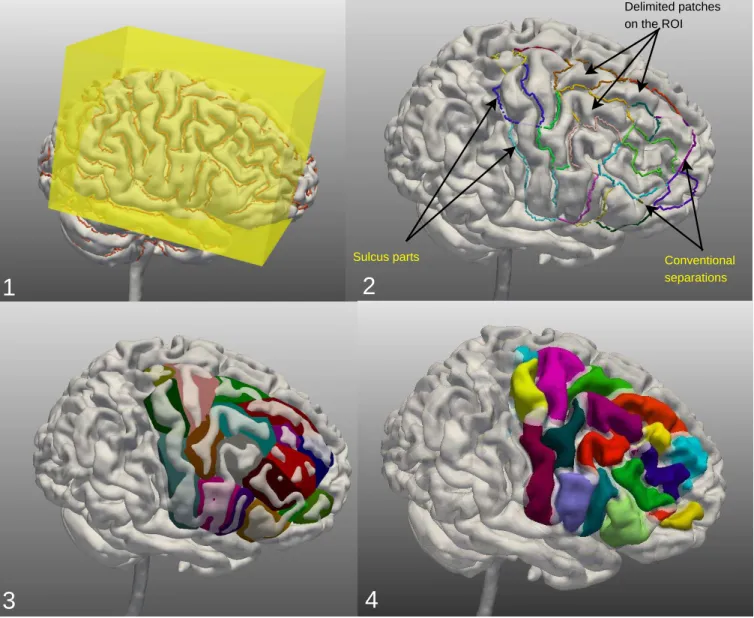
Definition 1: A ROI (Region Of Interest) is a region on the brain surface that a user wishes to annotate. Our approach is a ROI approach since practitioners are mostly interested in a specific region of the brain. In our application, the ROI is selected by the user by means of a 3D box (Figure 1-1) that allows one to select a 3D volume of the brain.
Definition 2: A sulcus part (Figure 1-2) is a part of an external outline of a sulcus. The sulcus parts are organized in a graph describing the connections between them.
Definition 3: A conventional separation (Figure 1-2) is a fictitious line added by the user in order to connect two sulcus parts separated by a gyrus. Conventional separations allow to obtain closed polygons (the patches).
Definition 4: A patch (Figure 1-2) is a subset of the brain surface, corresponding to part of a gyrus, and delimited by a set of continuous sulcus parts and conventional separations.
Definition 5: An image interpretation consists of a set of labels associated with the patches and the sulcus parts of a Region Of Interest (ROI); each patch and each sulcus part has a single label.
Definition 6: A consistent interpretation is an interpre-tation where each patch label and each sulcus part label is consistent with the prior knowledge about the sulco-gyral anatomy encoded in the ontology and with the information supplied by the user.
III. SYSTEMOVERVIEW
The overall labeling process involves three steps (named (a) (b) (c) in Figure 2) composed of:
• Step a (pre-treatments):
– brain segmentation and external outlines of sulci
Delimited patches on the ROI Conventional separations Sulcus parts
1
2
3
4
Fig. 1: 1) ROI selection by centering a 3D box on the ROI to be annotated; 2) patch definition by introducing conventional separations; 3) construction of patch surfaces in order to enable user interactions with the patches; 4) real 3D definition of patches. Atlas-based pre-labelling of patches b-1 Patches description
Atlas Matching rules
Sorting of possible interpretations of patches b-2 Topological knowledge Interactive selection of best interpretation of patches b-3 Final labelling of patches and sulci c-1 Ontology + rules Registration Matrix Sub-graph of sulci Patches labelling hypotheses Possible interpretations of patches Best interpretation of patches User Final annotations of patches and sulci (b) (c) Brain segmentation and external sulci
traces extraction Brain Graph of sulci ROI selection and patches definition User (a) a-1 a-2
Fig. 2: Complete labeling process. Bent corner squares: knowledge, Squares: treatments, Circles: input-output data. The numbers (a1, a2, b1, b2, b3, c1) in the squares correspond to the various treatments referred to in the System Overview section.
– ROI selection and patch definition (a-2).
• Step b (patch labeling):
– atlas pre-labeling of patches: done by matching the
sub-graph of sulcus parts belonging to the ROI with an atlas [12] (b-1);
– consistent interpretations computing for the patches:
inferred by a CSP solver, based on our prior knowl-edge about the spatial arrangement of the gyri and parts of gyri in the brain (b-2);
– best-interpretation computing for the patches:
deter-mined interactively using information supplied by the user (b-3).
• Step c (sulci identification): done using the best
interpre-tation computed for the patches, the description of the patches, and the logical definitions of the sulci in the ontology (c-1).
The final annotations for the patches and the sulcus parts are generated in standard Web languages to facilitate their use by Semantic Web technologies. Before generating the final annotation file, metadata are added to final patches and sulcus parts labels; these metadata provide information about the version of the ontology used, the atlas used, the user who annotated the ROI, etc.
IV. METHOD
We first introduce the knowledge sources used in the system, then we describe the various steps of the reasoning process.
A. Knowledge Involved in the Reasoning
The system combines numerical and symbolic knowledge in order to annotate graphical primitives extracted from the images.
1) Numeric Knowledge: A number of works in field of brain imaging are based on a statistical approach and use prior knowledge represented in atlases [6], [8], [13], [14]. SPAMs [12] (Statistical Probability Anatomy Maps) are examples of these atlases, which we used in our work. SPAMs are 3D prob-abilistic maps associated with particular anatomical structures. The value at each voxel position represents the probability of belonging to this structure at that location [15]. The SPAMs were derived from a database of 305 normal subjects, after re-alignment of MRI data into a common reference system (called stereotaxic space).
Figure 3 shows two SPAMs corresponding to the right precentral and postcentral gyri.
2) Symbolic Knowledge:
a) Sulco-gyral anatomy ontology: consists of an OWL DL (OWL based on Description Logics) ontology which models the mereo-topological features of the sulci and gyri. The set of axioms defining the sulci and gyri classes and their relationships in the ontology form the TBox component of the ontology (the terminological component). Assertions about individuals derived from the images form the ABox compo-nent of the ontology (the assertion compocompo-nent). The resources used to model our ontology (i.e., the TBox component of the ontology) were:
Fig. 3: 3D view of two SPAMs corresponding to the right precentral and postcentral gyri (left: lateral view; right: coronal view).
• a previous work by Dameron [16], [17] on brain anatomy
modeling;
• the Foundational Model of Anatomy ontology (FMA 3
[18]);
• Ono’s atlas of the cerebral sulci [19]; • and the expertise of a neuroanatomist.
In point of fact, we based our ontology on the previous work of Dameron, but this work was not complete: some anatomical structures were not defined, so we completed it with knowledge drawn from the FMA. However, the FMA does not provide (at least for the moment) definitions for sulci. We thus got these definitions from Ono’s atlas. The role of the neuroanatomist was to help us define new structures that were not defined either in Dameron’s work or in the FMA.
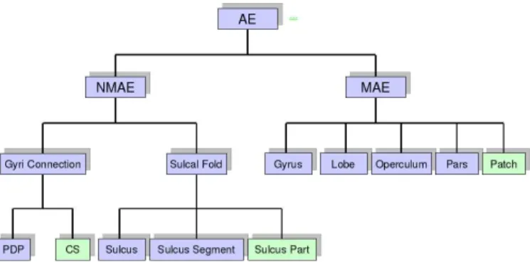
Fig. 4: Hierarchical organization of concepts in the ontology:
AEmeans Anatomical Entity,(N)MAEmeans (Non) Material
Anatomical Entity, PDP means Pli De Passage (which are
small gyri buried into the depth of the main sulci) and CS
means Conventional Separation. The concepts of the applica-tive ontology (in green) are: Conventional Separation, Sulcus Part, and Patch. Two other classes of the applicative ontology (AttributedEntity and Orientation classes) are not shown on this hierarchical structure because they do not refer to any brain anatomical structure, or to structures extracted from images.
In our system, the logical definitions of the sulci in the ontology serve, for example, to identify sulcus parts using a DL reasoner. Figure 5 shows the definition, in Prot´eg´e4, of
the right superior precentral sulcus part. In order to maintain truly sharable knowledge, we have separated generic concepts and generic relations from those specific to our annotation application (Figure 4). We thus obtained two ontologies: a
sharable ontology containing generic concepts like Gyrus
and generic relations like isAnatomicalPartOf, and an
applicative ontology that contains concepts and relations used in the specific context of our annotation application, such as Patch. The applicative ontology imports the sharable
ontology, thanks to theIMPORTSproperty offered byOWL.
The sharable ontology contains 29 relations and, for each hemisphere, logical definitions of 49 gyri, 5 lobes, 3 opercu-lum, 17 gyri parts and 44 sulci. Each concept has a unique logical definition. Some concepts are defined solely by their mereo-topological relationships with their neighbors, while others involve mereo-topological and directional relationships with their neighbors. A DL representation only uses binary relations. However, our application needs to use ternary rela-tions like thebounds relationship that relates three entities: the first one is bounded by the second entity, and the third entity expresses the directional relation (called orientation in the applicative ontology) in which the second entity bounds the first one. Indeed, in terms of this ternary relation, the orien-tation exists only if the boundary exists. In order to transform ternary relations into binary relations, we used, in traditional form, a reification 5, which consists of the introduction of
a new concept: AttributedEntitywith two properties:
has_entity and has_orientation that point, respec-tively, to the patch and orientation involved. Figure 6 shows
an example of reification transforming the relation bounds
into a binary relation; the domain of boundsis the concept
SulcusPart, its range is the class AttributedEntity
pointing to the classes Patch and Anterior through the
properties has_entity and has_orientation,
respec-tively.
Several relationships are defined in our sharable ontology, the most important of which are summarized below; for more details on the other relationships see [20]:
• isMAEBoundedBy: used to signify that a material
anatomical entity is bounded by a sulcal fold. Hence, its domain is the class Material Anatomical Entity (MAE) and its range is the classSulcal Fold. It is used, for
exam-ple, to signify that the Right Precentral Gyrus
is bounded by the Right Central Sulcus. The
inverse relation ofisMAEBoundedByisMAEBounds;
• isMAEConnectedTo: signifies that two material
anatomical entities are connected, i.e., there is a Pli De Passageor anOperculusthat connects them. Its domain and its range are the class Material Anatomical Entity (MAE), and it is a symmetric relationship;
• isSFContiguousTo: signifies that two sulcal folds
are contiguous, i.e., there is a Pli De Passage or
4http://protege.stanford.edu/
5http://www.w3.org/TR/swbp-n-aryRelations/
an Operculusthat separates them. Its domain and its range are the classSulcal Fold, and it is a symmetric relationship;
• isSFConnectedTo: signifies that two sulcal folds are
connected, i.e., they share a sulci connection. Its domain and its range are the class Sulcal Fold, it is also a symmetric relationship;
• isMAEContiguousTo: signifies that two material
anatomical entities are contiguous, i.e., they are separated by a Sulcal Fold. Its domain and its range are the
class Material Anatomical Entity (MAE), and it is a
symmetric relationship.
All these relationships are used to define the gyri and the sulci concepts, relying on the DL formalism and using OWL DL for their representation.
s121 attEnt0 p_0 anterior bounds has_entity has_orientation SulcusPart bounds has_entity has_orientation SulcusPart Attributed Entity Anterior Patch
Fig. 6: Example of class and instance reifications, respectively. b) Inference Rules: Our sulco-gyral anatomy ontology is enriched by a set of rules, represented in SWRL6, the Semantic
Web Rule Language. These rules are used to infer new knowledge by matching symbolic and numerical knowledge.
They are also used to infer boundary betweenSulcusPart
andPatchclasses from the reified relationbounds.
For example, the rule: bounded by(p, ae) ∧ Patch(p) ∧
AttributedEntity(ae) ∧ hasEntity(ae, sp) ∧ SulcusPart(sp) ∧ hasOrientation(ae, a) ∧ Anterior(a) → bounded by(p,sp)
signifies that if a patch p is bounded by an attributed entity ae, and this latter has as entity a sulcus part sp, then p is inferred as bounded by sp also. More details about the rules can be found in [21].
c) Symbolic constraints: The ontology knowledge was also used to manually specify the definitions of the spa-tial constraints between gyri and gyri parts, in order to be used by the CSP solver when labeling the patches. This takes into account both the respective directional and adjacency relationships between the gyri and gyri parts. We thus defined six directional constraints corre-sponding to the six spatial directions, each represented by
a set of tuples, such as (RightPreCentralGyrus,
RightPostCentralGyrus), one of the tuples
defin-ing the anteriorTo constraint, which signifies that
Fig. 5: Example of concept definition in Prot´eg´e: the right superior precentral sulcus part is defined as a sulcus part that delimits (bounds) some part of the right precentral gyrus and some part of the right superior frontal gyrus, and only parts of these two gyri. Concepts and relations of the sharable ontology are preceded by the namespace ’brain:’.
a part of the right precentral gyrus may be anterior to a part of the right postcentral gyrus. Some tuples
may be in the form (RightSuperiorFrontalGyrus,
RightSuperiorFrontalGyrus), signifying that a part of the right superior frontal gyrus may be anterior to an-other part of the same gyrus. As opposed to the directional constraints, the adjacency constraints between gyri and parts of gyri are of the utmost importance, because they have the advantage of being independent of the coordinate system and of the directional relation computation programs, which may make some erroneous decisions. For this reason, the adjacency constraints are given priority in our system.
B. Labeling Process
1) Generation of Hypotheses for the Patches:
a) Patch Description: The system first extracts the sub-graph of the sulcus parts corresponding to the ROI selected by the user. Next, the user defines a set of contiguous patches by introducing a number of conventional separations (Figure 1). Then, the system computes the topological and directional relationships between neighboring patches, and between the patches and the sulcus parts forming them. The description of these spatial relations is represented in OWL (file#1), which will be used later in the various steps of reasoning. Neighboring patches are those sharing a sulcus part or a conventional separation. Directional relations between two
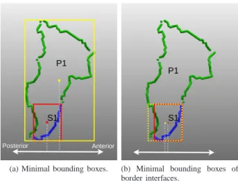
neighboring patches are established by calculating the vector joining the barycenters of their respective minimum bounding boxes. By minimum bounding box we mean the smallest parallelepiped that encloses a patch or a sulcus part.
S1 P1
.
.
Posterior Anterior
(a) Minimal bounding boxes.
S1 P1
.
.
(b) Minimal bounding boxes of border interfaces.
Fig. 7: (a) if we use the barycenter of the minimum bounding
box of the patch P1 and the barycenter of the minimum
bounding box of the sulcus part S1, then the directional
relation will be wrong in this case. However, if we use the barycenters of their minimum bounding boxes of border interfaces (b), then the directional relations will be correct.
Directional relations between a patch and the sulcus parts forming it are calculated using the method proposed in [22], [23]. In this method, the authors propose to use minimum bounding boxes of border interfaces instead of minimum bounding boxes. By ”border interface”, the authors mean the border part of a region which, given a cardinal direction, is in front of another region. Indeed, in some cases, the minimum bounding boxes method may not provide an accurate directional relation. This is illustrated in a simplified example (Figure 7-(a)), where the sulcus part S1 is calculated as being
posterior to the patch P1, whereas it is anterior to it. However,
if we use the minimum bounding boxes of border interfaces, then S1 will be calculated as anterior to P 1 (Figure 7-(b)),
which provides a more accurate spatial analysis.
b) Atlas Matching: The sulcus parts of the ROI sub-graph are transformed into the SPAMs space (stereotaxic space) thanks to the registration matrix estimated during the registration of MRI images onto a reference image aligned
with the stereotaxic space obtained from BrainWeb7. This
registration was made using our software described in [24]. This transformation A, which moves each point p to p′, can be
expressed as : p′ = A(p) = R
x(φx)Ry(φy)Rz(φz)GSp + t,
where Rx(resp. Ryand Rz) is a rotation around the x (resp. y
and z) axis, φx, φy and φz are parameters, G and S are shear
and scale matrices, and t= (tx, ty, tz) is a translation [24].
Next, a program analyzes the position of each sulcus part with respect to each SPAM, and determines whether it bounds it or not, and with which directional relation. This information is also represented in OWL (we call it file#2). The matching of information from file#1 and file#2, in the case of normal subjects, is done by SWRL rules of the following form:
• bounds(x,y) ∧ SulcusPart(x) ∧ Patch(y) ∧ anteriorTo(x,y) ∧
bounds(x,z) ∧ Gyrus(z) ∧ anteriorTo(x,z) → partOf(y, z)
This rule infers that a patch y is a part of a particular gyrus
z of the ontology if y and the SPAM corresponding to z are
both bounded by a sulcus part x and are both anterior to it. Six similar rules are defined in our system for normal subjects and correspond to the six spatial directional relations (anteriorTo, posteriorTo, superiorTo, inferiorTo, leftTo, and rightTo). In pathological cases, the following rule is used: bounds(x,y) ∧
SulcusPart(x) ∧ Patch(y) ∧ bounds(x,z) ∧ Gyrus(z) → partOf(y, z).
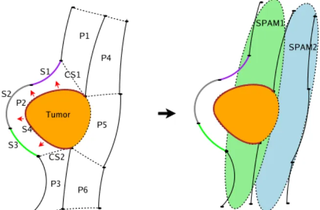
It does not take into consideration the directional relations between the sulcus parts and the SPAMs, because they might lead to erroneous decisions due to displacements related to some pathology. Figure 8 shows an example illustrating why directional relations are not considered in pathological cases. In both cases (normal and pathological), matching rules allow for assigning to each patch a set of labels viewed as initial hypotheses. These rules are activated using the following
SPARQL8 query: SELECT ?x ?y WHERE { ?x rdf:type
a:Patch ; a:partOf ?y}.
2) Consistent Interpretations for Patches: A CSP consists of a number of variables and a number of constraints. A variable is defined by its domain, i.e., the set of values that can be assigned to this variable. A constraint relates several
7http://www.bic.mni.mcgill.ca/brainweb/ 8http://www.w3.org/TR/rdf-sparql-query/
Fig. 8: Let us consider the simplified ROI on the left, where six patches (P1 .. P6) are delimited around the lesion (a tumor, in this case), and two SPAMs SPAM1 and SPAM2 on the right. Let us consider particularly the patch P2 that is displaced by the tumor as indicated by the red arrows. P2 is bounded by the sulcus parts S1, S2, S3 and S4. It is also bounded by the conventional separations CS1 and CS2 added by the user. After the transformation of the sulcus parts of this ROI into the SPAMs space, we see that P2 does not coincide with SPAM1 (as do the rest of the patches) because of the shift caused by the tumor, and it is almost outside this SPAM. However, the sulcus parts S1 and S4 are still inside SPAM1, and consequently still bounding SPAM1 even if with a wrong directional relation (orientation). This is why the matching rule, used in the case of pathological subjects, does not take the directional relations into consideration.
variables and restricts the values of the variables in question to legal assignments. Constraint reasoning is the process of computing a solution to the given CSP, i.e., an assignment of values to the variables that satisfy all the given constraints on the variables [25]. The adaptation of our problem to a CSP was easy. In fact, the patches represent the variables, the hypotheses computed for the patches represent the domains of the variables, and the spatial relations between the patches represent the constraints.
Algorithm of Transformation into a CSP Problem: Let
T(P, SR) be the description of the patches, where P is the
set of extracted patches and SR the spatial relations defined on the elements of P . We have, for each patch p∈ P , a set
of labels (hypotheses) denoted as lp(p). Each spatial relation r∈ SR is a tuple < type, (p1, p2) > where type refers to the
type represented by the spatial relation and (p1, p2) are the
patches the spatial relation is defined on. The transformation of T into a CSP is done by the following algorithm:
1) for each p∈ P create a variable vp;
2) if the user validates a given label lifor a given patch pi
then set D(vp) = l
i; else set D(vp) = lp(p); (D(vp) is
the domain of the variable vp);
3) for each spatial relation r ∈ SR between two patches
p1, p2∈ P add a binary spatial constraint between the
variables vp1 and vp2 of the relevant type.
The CSP solver provides all possible consistent interpre-tations for the patches with respect to our priori knowledge
about the spatial arrangement of the gyri and parts of gyri in the brain.
3) User-Assisted Determination of the Best Interpretation for Patches: The goal is to determine, from a user perspective, which is the best interpretation among those returned by the CSP solver. To reach this goal, the user is invited to assign a label to a patch exhibiting different labels in different interpretations. The system then eliminates all the proposed interpretations that are not consistent with the user’s choices (Figure 2-b). The interactions are repeated until only one interpretation remains for the patches.
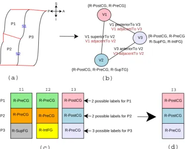
4) Illustrative example: Consider the simple example
depicted in Figure 9, exhibiting three patches (P1, P2,
P3) delimited in the ROI. The goal is to find the correct
labels for the three patches. From the patch description we have, among others, the following spatial relations:
posteriorTo(P1, P3), adjacentTo(P1, P3),
anteriorTo(P3, P2), adjacentTo(P3, P2),
superiorTo(P1, P2), and adjacentTo(P1, P2). We suppose that the following hypotheses are inferred for the patches from the SPAMs by the matching rules
above: P1(R-PreCG, R-PostCG), P2(R-PostCG,
R-PreCG, R-SupTG), and P3(R-PreCG, R-SupFG, R-IntFG, R-PostCG). I2 P1 P2 P3 S1 S2 V1 V2 V3 V1 superiorTo V2 V1 adjacentTo V2 V1 posteriorTo V3 V1 adjacentTo V3 V3 anteriorTo V2 V3 adjacentTo V2 {R-PostCG, R-PreCG}
{R-PostCG, R-PreCG, R-SupTG}
{R-PostCG, R-PreCG R-SupFG, R-IntFG} P1 P2 P3 I1 R-PreCG R-PreCG R-PreCG I3 R-PostCG R-PreCG R-PostCG
R-SupFG R-IntFG R-PreCG
2 possible labels for P1
2 possible labels for P2
3 possible labels for P3
I3 R-PostCG R-PostCG R-PreCG (a) (b) (c) (d) S I P A
Fig. 9: Simplified example: (a) a ROI comprised of three patches; (b) transformation to a CSP representation: V1, V 2
and V3 variables are associated with the patches P 1, P 2
and P3 and the spatial relations between patches are
trans-formed into constraints between variables; (c) three consistent interpretations computed for the three patches; (4) the best interpretation for the patches.
The graphical representation is transformed into a CSP rep-resentation (Figure 9), and its resolution returns three possible interpretations for the patches (I1,I2, and I3) (Figure 9). Now, the system asks the user to validate one label for the patch having the highest number of possible labels in the different interpretations (P3in the example, since it has three possible labels). If the user validatesP3(R-PreCG), then the
system eliminates the previous interpretations where the label ofP3differs fromR-PreCG. Thus, the best interpretation in this case isI3(Figure 9).
5) Sulcus Parts Labeling: Sulcus parts labeling relies on a DL reasoning (Figure 2-c). The system uses the best interpre-tation computed for the patches, the topological and directional relations calculated between the sulcus parts and the patches, and the logical definitions of the sulci in the ontology. Let us consider sulcus part S1 in Figure 9. The best interpretation
computed above was I3. From the patch description, it is also
known that S1 bounds P 1 with an anterior directional relation
and P3 with a posterior directional relation. Suppose that the
right central sulcus part has the following logical definition in the applicative ontology:
• RightCentralSulcusPart ≡ (∃ bounds.((∃ hasEntity.(∃
partOf.brain:RightPostCentralGyrus)) ⊓ (∃
hasOri-entation.Anterior))) ⊓ (∃ bounds.((∃ hasEntity.(∃
partOf.brain:RightPreCentralGyrus)) ⊓ (∃
hasOri-entation.Posterior))) ⊓ (∀ bounds.((∃ hasEntity.(∃
partOf.brain:RightPreCentralGyrus)) ⊔ (∃ hasEntity.(∃
partOf.brain:RightPostCentralGyrus))).
This logical expression signifies that a part of the central sulcus of the right hemisphere bounds a part of the right postcentral gyrus with an anterior orientation (or direction), and a part of the precentral gyrus with a posterior orientation, and that it does not bound any other gyri. Consequently, sulcus
part S1 will be identified as aRightCentralSulcusPart
instance.
6) Final Annotation For Patches and Sulcus Parts: The patches and sulcus parts annotations are stored in RDF, and include metadata stating the name of the atlas used, the ontology version, etc. The concepts referred to in this file are those defined in the ontology. Figure 10 shows part of an annotation file.
Fig. 10: Example of RDF representation of patch and sulcus part annotations.
V. SYSTEMIMPLEMENTATION ANDEVALUATION
A. A Web Service Implementation
The proposed system was implemented using Web services
technology. The various services run on an Axis server,
and are executed by gsoap clients using a visualization
tool namedGisViewer, developed with the VisAGes9 team
(Figure 11).
The Web service architecture has, among others, the follow-ing advantages:
Fig. 11: A Web service implementation of the system.
• easy use of the system: indeed, users do not need to install
the labeling system on their machines, they only need to install the GisViewer software in order to annotate their brain images;
• only one installation of the reasoning tools involved in
the system is needed as the inference engine and the CSP solver;
• users can access the same version of the ontology and
symbolic constraints on the server, which could be up-dated and improved on the server only;
• atlases are only put on the server, so users do not need
to know anything about them.
B. Details of the different Web Services
Six Web services were implemented as shown in Figure 11.
• Service 1: Easy authentication: only a user name and a
password are needed;
• Service 2: This consists of a query, made in order to
get the complete list of gyri names from the ontology. It takes as input the query and the ontology, and it returns as output a list of gyri names;
• Service 3: This consists of the atlas matching, explained
in Section 3. It takes as input the SPAMs’ atlas, the registration matrix and the sub-graph of the external outlines of the sulci. It returns as output the description of the topology and the directional relations between the external outlines of the sulci and the SPAMs;
• Service 4: The generation of hypotheses, by matching
information deduced from the atlas and the patches’ description. It takes as input the matching rules, the patches’ description file and the output of the service 3. It returns as output a set of hypotheses (possible labels) for each patch in the ROI (Figure 12);
• Service 5: Determination of consistent interpretations,
based on CSP reasoning. This service takes as input the patches’ description file and the output of the service 4. It returns as output a set of consistent interpretations. Each interpretation consists of one label for each patch of the ROI. The user can navigate through these interpretations
using the Next interpretation and Previous
interpretation buttons. The best interpretation is calculated interactively with the user (Figure 13);
• Service 6: Identification of sulcus parts, based on DL
reasoning. It takes as input the ontology, the patches’ description file and the output of the service 5. It returns as output the identifiers and labels of the sulcus parts that have been classified by the reasoner based on the logical definitions of the sulci in the ontology. The final annotations of the patches and sulcus parts are shown on the image (Figure 14) and stored in an RDF file after adding metadata that document which version of the ontology was used, which atlas, etc.
Fig. 14: Patch and sulcus part annotations: the patches have their labels in front of them, and sulcus parts are assigned colors that help the user to identify them; the correspondence is given in a legend box (not shown here)
C. Experiments and Materials
The experiments were performed using T1-MRI images ob-tained with a 3T scanner (Philips Gyroscan Achieva 3T) from ten normal subjects and five patients. In the five pathological cases, the pathology types involved were low or high-grade glioma located in the right frontal lobe. We used only cases where a specialist deemed that they had caused a shift. Figure 15 shows an example illustrating the extent of the lesion in a patient with a tumor. The brain segmentation and the extraction of the external outlines of the sulci were done with Brain-visa10 tools and Vistal11, respectively. We used 44 SPAMs corresponding to the main gyri. The various programs were implemented in C++ and Java, with the connection between C++ and Java programs made possible using JNI (Java Native Interface). The ontology was created and edited using the Prot´eg´e software. The rules were created and edited using the
SWRL12 Plugin. The results for the patches were obtained
using the Java Constraint Library JCL13 (a CSP solver), and
the sulcus parts were classified using the KAON214 reasoner
(an inference engine for rule-extended ontologies).
10http://brainvisa.info/index\ f.html
11http://www.irisa.fr/vista/Themes/Logiciel/VIsTAL/VIsTAL.html 12http://protege.cim3.net/cgi-bin/wiki.pl?SWRLTab
13http://liawww.epfl.ch/JCL/ 14http://kaon2.semanticweb.org/
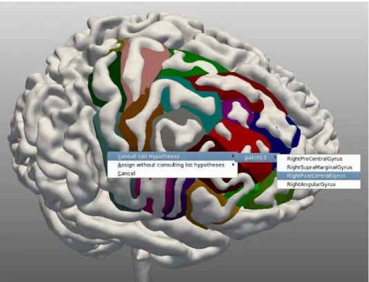
Fig. 12: A menu showing hypotheses inferred for the patch selected by the user. The user has three options: 1) validate a label among the hypotheses inferred by the system; 2) validate a label from a complete list obtained from the ontology; 3) do nothing.
Fig. 13: User interactions for computing the best interpretation: the patches already identified have their labels in front of them and those that the system could not identify thus far are marked with a question mark. The user can select these and the system will propose a set of possible labels.
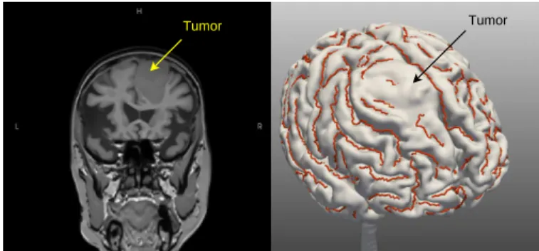
Tumor Tumor
Fig. 15: An example of the extent of a lesion as discussed in this work. We can see the lesion (a tumor, here) and the displacement of the anatomy that it causes.
D. Experimental Protocol
Two physical and distinct persons were involved in the evaluation: a neuroanatomy specialist and a user who was not a specialist, but all his interactions with the system were based on information that had been given to him by the specialist. In the regular use of the system, the user needs to have some knowledge of anatomy, especially to define the patches and provide the few labels that the system needs. So, the user interacted with the system, relying on the specialist’s knowledge. Evaluation of the system was done as follows:
• ROIs were defined by the neuroanatomy specialist and
included the superior frontal gyrus, the middle frontal gyrus, the inferior frontal gyrus, the precentral gyrus, the postcentral gyrus, the central sulcus, the superior precentral sulcus, the intermediate precentral sulcus, the inferior precentral sulcus, the superior frontal sulcus and the inferior frontal sulcus regions;
• the patches were defined manually by the user, who was
asked to define conventional separations, as needed, in order to obtain closed polygons with as regular a shape as possible, and also as recommended by the specialist;
• the specialist assigned labels to all patches in all cases;
• the hypotheses were automatically computed for the
patches;
• in each case, the user was asked to validate two labels
for two patches, based on the labels previously defined by the specialist;
• in each case, the user had to interact with the system at
most five times in order to determine the best interpreta-tion, also relying on the labels previously defined by the specialist;
• after each user interaction, we compared the results
generated by the system with the labels assigned by the specialist, which were taken as a gold standard.
The same procedure was applied to the fifteen MRI datasets, except for the matching rules since directional relations were not considered in case of pathological data.
Logical definitions of the sulci: The logical definitions of the sulci used in the evaluation were the following:
• RightCentralSulcusPart ≡ SulcusPart ⊓ (∃ bounds.(∃ partOf.brain:RightPostCentralGyrus)) ⊓ (∃ bounds.(∃ partOf.brain:RightPreCentralGyrus)) ⊓ (∀ bounds.((∃ partOf.brain:RightPreCentralGyrus)) ⊔ (∃ partOf.brain:RightPostCentralGyrus)) • RightSuperiorPreCentralSulcusPart ≡ SulcusPart ⊓ (∃ bounds.(∃ partOf.brain:RightPreCentralGyrus)) ⊓ (∃ bounds.(∃ partOf.brain:RighSuperiorFrontalGyrus)) ⊓ (∀ bounds.((∃ partOf.brain:RightPreCentralGyrus)) ⊔ (∃ partOf.brain:RightSuperiorFrontalGyrus)) • RightIntermediatePreCentralSulcusPart ≡ SulcusPart ⊓ (∃ bounds.(∃ partOf.brain:RightPreCentralGyrus)) ⊓ (∃ bounds.(∃ partOf.brain:RighIntermediateFrontalGyrus)) ⊓ (∀ bounds.((∃ partOf.brain:RightPreCentralGyrus)) ⊔ (∃ partOf.brain:RightIntermediateFrontalGyrus)) • RightInferiorPreCentralSulcusPart ≡ SulcusPart ⊓ (∃ bounds.(∃ partOf.brain:RightPreCentralGyrus)) ⊓ (∃ bounds.(∃ partOf.brain:RighInferiorFrontalGyrus)) ⊓ (∀ bounds.((∃ partOf.brain:RightPreCentralGyrus)) ⊔ (∃ partOf.brain:RightInferiorFrontalGyrus)) • RightSuperiorFrontalSulcusPart ≡ SulcusPart ⊓ (∃ bounds.(∃ partOf.brain:RightSuperiorFrontalGyrus)) ⊓ (∃ bounds.(∃ partOf.brain:RighIntermediateFrontalGyrus)) ⊓ (∀ bounds.((∃ partOf.brain:RightSuperiorFrontalGyrus)) ⊔ (∃ partOf.brain:RightIntermediateFrontalGyrus)) • RightInferiorFrontalSulcusPart ≡ SulcusPart ⊓ (∃ bounds.(∃ partOf.brain:RightInferiorFrontalGyrus)) ⊓ (∃ bounds.(∃ partOf.brain:RighIntermediateFrontalGyrus)) ⊓ (∀ bounds.((∃ partOf.brain:RightInferiorFrontalGyrus)) ⊔ (∃ partOf.brain:RightIntermediateFrontalGyrus)) E. Results
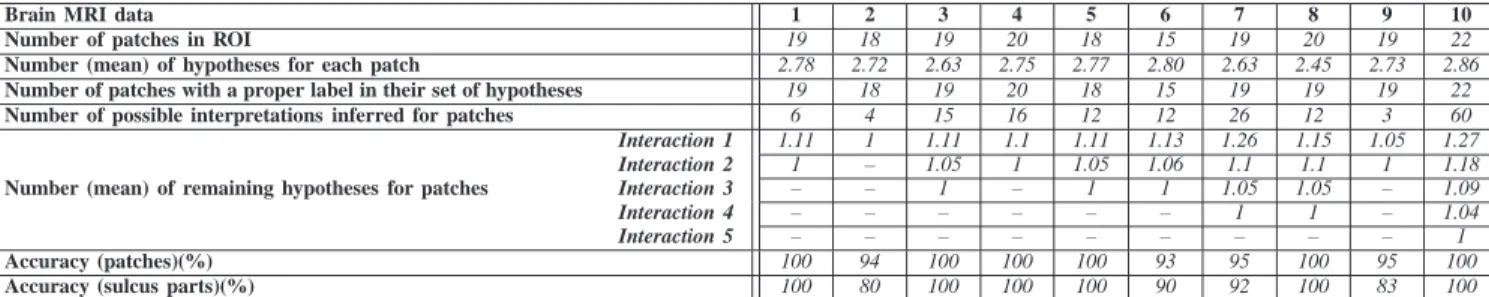
Tables I and II show the results obtained. We note that:
• the number of patches in ROIs was around 19 (mean:
18.9, std. dev: 1.79) in normal cases and 19 (mean: 19.6, std. dev: 3.29) in pathological cases;
• the number of hypotheses inferred for each patch, by
means of the matching rules, was less than 3 (mean: 2.71, std. dev: 0.12) for normal cases and (mean: 2.39, std. dev: 0.29) for pathological cases. These hypotheses are very helpful for the user when he explores/identifies a ROI on the brain, since the number of possible labels for each patch is reduced from 44 (number of SPAMs) to less than 3 (number of possible labels);
• in all ROIs, the correct label for each patch was included
in the set of hypotheses inferred by the system. This shows that the matching rules are very efficient. Thus, in each set of hypotheses, we have the correct label and one or two other possible labels;
• the number of consistent interpretations was about 16
(mean: 16.6, std. dev: 16.65) for normal cases and 16 (mean: 16.4, std. dev: 15.19) for pathological cases. This highlights the fact that the spatial constraints support-ing the CSP resolution reduce the number of possi-ble solutions. Indeed, without spatial constraints, for a
ROI with 19 patches and 3 possible labels for each,
the number of possible interpretations would have been
319
= 1162261464 instead;
• in most cases (both normal and pathological), the number
Brain MRI data 1 2 3 4 5 6 7 8 9 10
Number of patches in ROI 19 18 19 20 18 15 19 20 19 22
Number (mean) of hypotheses for each patch 2.78 2.72 2.63 2.75 2.77 2.80 2.63 2.45 2.73 2.86
Number of patches with a proper label in their set of hypotheses 19 18 19 20 18 15 19 19 19 22
Number of possible interpretations inferred for patches 6 4 15 16 12 12 26 12 3 60
Number (mean) of remaining hypotheses for patches
Interaction 1 1.11 1 1.11 1.1 1.11 1.13 1.26 1.15 1.05 1.27 Interaction 2 1 – 1.05 1 1.05 1.06 1.1 1.1 1 1.18 Interaction 3 – – 1 – 1 1 1.05 1.05 – 1.09 Interaction 4 – – – – – – 1 1 – 1.04 Interaction 5 – – – – – – – – – 1 Accuracy (patches)(%) 100 94 100 100 100 93 95 100 95 100
Accuracy (sulcus parts)(%) 100 80 100 100 100 90 92 100 83 100
TABLE I: Experimental results: Normal cases
Brain MRI data 1 2 3 4 5
Number of patches in ROI 25 20 17 17 19
Number (mean) of hypotheses for each patch 2.68 2.70 2.17 2.05 2.36
Number of patches with a proper label in their set of hypotheses 25 20 17 17 19
Number of possible interpretations inferred for patches 40 18 2 4 18
Number (mean) of remaining hypotheses for patches
Interaction 1 1.16 1.2 1 1 1.21 Interaction 2 1.12 1.1 – – 1.15 Interaction 3 1.04 1.05 – – 1.05 Interaction 4 – 1 – – 1 Interaction 5 – – – – – Accuracy (patches)(%) 100 100 94 93 95
Accuracy (sulcus parts)(%) 100 100 80 90 88
TABLE II: Experimental results: Pathological cases
1 as of the first user interaction, which means that the
majority of patches are identified (each of them having only one label) with only one user interaction. In most other cases, the ROIs were completely identified by the third user interaction;
• the accuracy of identification is good both for patches and
sulcus parts. Indeed, the accuracy for patch identification
was about97% (mean: 97.7%, std. dev: 3.02) in normal
cases and96% (mean: 96.4%, std. dev: 3.36) in
patholog-ical cases; the accuracy for sulcus parts identification was about94% (mean: 94.5%, std. dev: 7.82) in normal cases
and91% (mean: 91.6%, std. dev: 8.53) in pathological
cases. The origin of the labeling errors was mainly due to two related factors: the fact that one directional relation only was computed, and the fact that our definitions of spatial constraints may not be complete-enough to match the unique directional relation found in the images.
For example, the tuple (RightPostCentralGyrus,
RightPostCentralGyrus) is one of the tuples defining the inferiorTo constraint, which allows a part
of the RightPostCentralGyrus to be inferior to
another part of the same gyrus. This tuple is not included in those defining the anteriorTo constraint, so a part of the RightPostCentralGyrus is not allowed to be anterior to another part of the same gyrus. However, in some cases, the directional relation initially extracted by the imaging tools between two patches that should
be parts of the RightPostCentralGyrus could be
anteriorTo instead of inferiorTo. This led to an improper identification of patches and consequently of sulcus parts, whose labels are partially based on the patch labels;
• another very interesting feature of the evaluation is that
there is no difference in accuracy between normal and pathological cases. This suggests that our method, in contrast to traditional ones, is resistant to shifts caused
by pathologies.
These results show that the proposed system can be very helpful to the user in obtaining consistent annotations for brain anatomy MR Images. It also helps to obtain annotations quickly, since a user needs less than two minutes to annotate the patches, and less than three minutes to automatically annotate the sulcus parts.
VI. DISCUSSION
Our approach differs in many ways from traditional methods of cortex segmentation in MRI images. It also differs from similar works on image annotation using Semantic Web tech-nologies, such as the method of Dasmahapatra et al. [26]. In particular, our identification process involves reasoning on topological properties of the entities to be labeled, based on the graphical information extracted from the image.
In terms of the ontology modeling, we used both Dameron’s work [16], [17] and FMA [18], since FMA did not provide the topological knowledge concerning the sulci and is not usable as a whole because of its huge size. For the representation of our ontology, we used OWL DL in order to facilitate its sharing and its use by programs.
More generally, a tradeoff must be found between the generality of an ontology, i.e., its applicability in one field and across several domains, and its precision, which determines its added value for specific applications. Another difficult issue with ontologies is modularity. A natural tendency is to gather into a single ontology all relevant concepts of a domain. This leads to huge ontologies, such as those found in the
biomedical field, e.g., Snomed-CT 15, Gene Ontology 16 or
the FMA. Another tradeoff concerns ”conflicting requirements for expressive power in the language used for semantic an-notation and the scalability of the systems used to process
15http://www.nlm.nih.gov/research/umls/Snomed/snomed main.html 16http://www.geneontology.org/
them” [2]. Several new profiles 17 of the OWL 2 ontology
language extension, which are specially adapted to deal with the different categories and sizes of ontologies and which can be more simply and/or efficiently implemented, will shortly
become W3C 18 recommendations.
We deliberately chose an approach that establishes cooper-ation between the user (who is supposed to have minimum skills in brain anatomy) and the system, taking advantage of specific skills of each of the two protagonists: the existing anatomical knowledge of the user, and the ability of the system to systematically apply rules and constraints in order to propagate the consequences of the user’s choices. The user thus plays an active part in the labeling process since he defines the patches and provides key indications that are used by the system to infer the best interpretation for the patches. In particular, he specifies conventional separations in order to obtain closed coutours (i.e., the patches), based on the automatically segmented external outlines of the sulci. We wish to emphasize that a certain anatomical knowledge is required in order to obtain a correct parcellation of the ROI to be annotated, since no patch should straddle two different gyri. Moreover, this approach allows imperfections in the initial extraction of sulci to be dealt with, in the sense that they do not prevent the user from defining patches and annotating them. However, in such a case, the quality of the annotations may be inferior: for example, if a sulcus part was not detected and was replaced by a user-defined conventional separation, then this characteristic will not be properly described.
In terms of handling pathological cases, our work was limited to confirming that our labeling process would be reasonably resistant to brain tumors, since it manipulates adjacency relationships rather than positions with respect to a particular spatial reference. However, our solution is limited; in particular, our system (especially our sulco-gyral ontology) does not represent pathological structures and the spatial relationships they have with the surrounding normal tissues, as shown in [27]. This kind of extension could be relevant, in the sense of providing a more precise description of the relationships between the pathology and the surrounding structures.
The tests described in the paper consist in evaluating the system performances. Actually, one expert neuroanatomist has participated in this evaluation, because the system is designed primarily to preparing procedures in neurosurgery. However, we believe that it is interesting now to test the system with different users having different experiences, to more generally assess its performances, usability and usefulness.
One important originality of our approach is that it allows one to define and share knowledge about anatomical entities, especially fine-grained structures, based on specific and precise
criteria. For example,Pars Orbitalisof theInferior
Frontal Gyrusis defined by its relationships with neigh-boring gyri and sulci. We believe that these constitute criteria potentially more accurate than the usual recourse to digital atlases. Also, in theory, the proposed approach would allow
17http://www.w3.org/TR/owl2-profiles/
18The World Wide Consortium - http://www.w3.org/
different typical patterns to be represented, as shown in Ono’s atlas, in order to deal with the anatomical variability between individuals. Currently, the ontology addresses this need via
the representation of unions (the ⊔ operator of OWL DL),
signifying, for example, that two gyri are neighbors and can be in continuity, i.e., there is aPli De Passageconnecting them, or can be contiguous, i.e., they are separated by a
Sulcus.
The reasoning over an OWL DL ontology extended with SWRL rules merits some attention. Indeed, an SWRL rule base and OWL ontology may be combined to obtain complete inferences [28]. OWL and SWRL are complementary: on one hand, OWL DL is restricted to tree-like rules, but provides both existentially and universally quantified variables and full monotonic negation. On the other hand, Horn rules are decidable logics: they are restricted to universal quantification, but allow for interaction of variables in arbitrary ways [29]. However, in general, combining rules and OWL DL ontolo-gies leads to undecidability. Therefore, in order to maintain decidable query answering for OWL DL ontologies extended with rules, existing reasoners are restricted to rules applicable only to individuals explicitly introduced in the ABox (known individuals), which are called DL-safe rules. SWRL rules may not be DL-safe; the KAON2 reasoner (which is used in our application) is based on the DL-safe rules assumption. Al-though the rules used for our system are not DL-safe, KAON2 provides the expected answers for the experiments reported. Indeed, in these cases the rules were fired because given the initial facts asserted, their body was satisfied by binding their variables to known individuals. However, this approach is not always relevant and situations may occur where solutions are missed because of the existential construct. For example, the
Patch class is defined with an existential element in the equivalent class expression. Hence, it may happen in some cases that a rule expressing the propagation of a property from parts to whole cannot be fired, because an instance ofPatch
is defined without being connected to a known instance of
gyrus by the relationpartOf. KAON2 does not make all the
consequences according to the first-order semantics of SWRL, but only consequences under ”the DL-safe semantics” [21]. In the context of our application, using rules with ontologies enables us to meet a significant subset of our requirements. In addition to the rules presented in the paper, standard rules may be needed for chaining ontology properties, such as the transfer of properties from parts to wholes (which are now representable in OWL 219), or dependencies in the brain
cortex, for example the rule: separatesMAE(y1, x1, x2) ∧
hasSegment(y2, y1) ∧ Sulcus(y2) ∧ MAE(x1) ∧ MAE(x2) ∧
SF(y1) → separatesMAE(y2, x1, x2) allows one to propagate
the separation relationship between anatomical entities from part to whole.
Let us now examine the adequacy of OWL DL reasoning in the process of image interpretation. In fact, OWL DL benefits from many years of DL research, where a formal semantics is well defined and formal properties in terms of complexity and decidability are well understood. This can help to avoid
guities in the ontology and the set of facts or instances asso-ciated with this ontology. Moreover, reasoning algorithms and
highly-optimized systems are available (FaCT++20, KAON2,
Pellet21, RacerPro22, etc.). These systems propagate inferences
based on the knowledge expressed in the TBox component of the ontology. They offer two reasoning services: consistency checking and instance checking. A DL system checks whether or not a set of instances is a partial model of the ontology, i.e., whether this set is consistent with the assertions expressed in the ontology. Consistency checking can, then, help to verify the consistency of an image interpretation. Instance checking allows one to determine the more specific concept in the ontology that can be applied to a particular instance such as a sulcus part. In our system, instance checking was used, for example, to determine the more specific concepts, defined in the ontology, that can be applied to the sulcus parts. However, in complex domains such as image interpretation, the use of DL systems becomes a complex problem. In point of fact, given a set of unnamed instances derived from an image, a very large number of combinations are possible when assigning labels to these instances, which can hardly be managed by DL-based classifications. This is why we used an atlas, which reduces the number of possible labels (called hypotheses) for the patches, and we used a CSP reasoning to determine combinations of those labels that are consistent with our a priori knowledge of the spatial arrangements of the gyri and parts of gyri. This way, our problem complexity was reduced and a DL reasoning was used to label sulcus parts and also to classify patches using more fine-grained concepts defined in the ontology, after being labeled as parts of gross anatomical structures defined in the atlas.
In the future, we plan to further improve the current system in several respects:
• definition of the conventional separations between gyri is
done manually in the current implementation and could be automated, e.g., using learning procedures;
• the use of atlases as a means to produce the initial
hypotheses could be optimized, e.g., by using different types of numerical atlases, better adapted to the particular case under study;
• the ontology could be refined, and this knowledge could
be directly used to automatically derive constraint defini-tions in the CSP problem;
• the use of fuzzy logic formalism to better represent
the spatial constraints and the spatial relations in the ontology, e.g., based on the work of Hudelot et al. [30], and the use of a powerful fuzzy CSP reasoner to label patches, when such a reasoner is available, will improve the quality of the annotations;
• Moreover, the dependence of the system’s performance
on initial processing steps (especially the definition of conventional separations) should be further investigated.
20http://owl.man.ac.uk/factplusplus/ 21http://clarkparsia.com/pellet/ 22http://www.racer-systems.com/
VII. CONCLUSION
We have presented a hybrid and interactive system devel-oped to semi-automatically label MRI brain images with se-mantic annotations and discussed the results of its evaluation. This approach is novel with several respects: (1) the use of a CSP solver to select consistent interpretations of the gyri parts, (2) the easy generation of semantically-rich annotations of gyral/sulcal structures, (3) the use of explicit prior knowledge described in a formal ontology, (4) its representation in OWL, the Ontology Web Language, to facilitate knowledge sharing. The system is implemented on a client-server architecture, using Web services and a visualization tool facilitating its use. The evaluation of the system showed good performance both on normal and pathological cases. In conclusion, the rapidity of its responses, its robustness for pathological cases and its Web services architecture, make the system a very promising tool for future use in the context of preparing for surgical procedures in neurosurgery.
ACKNOWLEDGMENT
We are grateful to Louis Collins of the Montreal Neurolog-ical Institute for providing us with the SPAMs database and to the Regional Council of Brittany for supporting this project. We also thank Abdallah Miladi, Souheil Selmi, Alexandre Abadie, and Mickael Pincepoche for their contribution to the implementation of the system.
REFERENCES
[1] A. Ruttenberg, T. Clark, W. Bug, M. Samwald, O. Bodenreider, H. Chen, D. Doherty, K. Forsberg, Y. Gao, V. Kashyap, J. Kinoshita, J. Luciano, M. S. Marshall, C. Ogbuji, J. Rees, S. Stephens, G. T. Wong, E. Wu, D. Zaccagnini, T. Hongsermeier, E. Neumann, I. Herman, and K.-H. Cheung, “Advancing translational research with the semantic web,” BMC
Bioinformatics, vol. 8 (suppl. 3), 2007.
[2] I. Horrocks, “Ontologies and the semantic web,” Commun. ACM, vol. 51, no. 12, pp. 58–67, 2008.
[3] O. Corcho, “Ontology based document annotation: trends and open research problems,” Int. J. Metadata Semant. Ontologies, vol. 1, no. 1, pp. 47–57, 2006.
[4] P. Jannin, X. Morandi, O. J Fleig, E. Le Rumeur, P. Toulouse, B. Gibaud, and J.-M. Scarabin, “Integration of sulcal and functional information for multimodal neuronavigation,” Journal of Neurosurgery, vol. 96, no. 4, pp. 713–723, April 2002.
[5] U. Ebeling, H. Steinmetz, Y. Huang, and T. Kahn, “Topography and identification of the inferior precentral sulcus in mr imaging,” American
Journal of Neuroradiology, vol. 10, no. 5, pp. 937–942, 1989.
[6] N. Tzourio-Mazoyer, B. Landeau, D. Papathanassiou, F. Crivello, O. Etard, N. Delcroix, B. Mazoyer, and M. Joliot, “Automated anatom-ical labeling of activations in spm using a macroscopic anatomanatom-ical parcellation of the mni mri single-subject brain,” NeuroImage, vol. 15, no. 1, pp. 273–289, January 2002.
[7] A. Cachia, J.-F. Mangin, D. Rivi`ere, D. Papadopoulos-Orfanos, F. Kherif, I. Bloch, and J. R´egis, “A generic framework for parcellation of the cortical surface into gyri using geodesic vorono¨ı diagrams,”
Medical Image Analysis, vol. 7, no. 4, pp. 403–416, 2003.
[8] B. Fischl, A. van der Kouwe, C. Destrieux, E. Halgren, F. S´egonne, D. Salat, E. Busa, L. Seidman, J. Goldstein, D. Kennedy, V. Caviness, N. Makris, B. Rosen, and A. Dale, “Automatically parcellating the human cerebral cortex,” Cerebral Cortex, vol. 14, no. 11-22, 2004. [9] C. Clouchoux, O. Coulon, J.-L. Anton, J.-F. Mangin, and J. R´egis, “A
new cortical surface parcellation model and its automatic implementa-tion,” in Medical Image Computing and Computer-Assisted Intervention
MICCAI (2), 2006, pp. 193–200.
[10] F. Baader, D. Calvanese, D. L. McGuinness, D. Nardi, and P. F. Patel-Schneider, Eds., The Description Logic Handbook: Theory,
[11] G. L. Goualher, C. Barillot, and Y. Bizais, “Modeling cortical sulci with active ribbons,” International Journal of Pattern Recognition and
Artificial Intelligence IJPRAI, vol. 11, no. 8, pp. 1295–1315, 1997.
[12] D. L. Collins, A. P. Zijdenbos, W. F. C. Baar´e, and A. C. Evans, “An-imal+insect: Improved cortical structure segmentation,” in Information
Processing in Medical Imaging IPMI, 1999, pp. 210–223.
[13] J.-F. Mangin, D. Rivi`ere, A. Cachia, E. Duchesnay, Y. Cointepas, D. Papadopoulos-Orfanos, D. L. Collins, A. C. Evans, and J. R´egis, “Object-based morphometry of the cerebral cortex,” IEEE Trans. Med.
Imaging, vol. 23, no. 8, pp. 968–982, 2004.
[14] D. Rivi`ere, J.-F. Mangin, D. Papadopoulos-Orfanos, J. M. Martinez, V. Frouin, and J. R´egis, “Automatic recognition of cortical sulci of the human brain using a congregation of neural networks,” Medical Image
Analysis, vol. 6, no. 2, pp. 77–92, 2002.
[15] A. Mechouche, X. Morandi, C. Golbreich, and B. Gibaud, “A hybrid system for the semantic annotation of sulco-gyral anatomy in mri im-ages,” in Medical Image Computing and Computer-Assisted Intervention
MICCAI (1), 2008, pp. 807–814.
[16] O. Dameron, B. Gibaud, A. Burgun, and X. Morandi, “Towards a sharable numeric and symbolic knowledge base on cerebral cortex anatomy: lessons from a prototype,” in American Medical Informatics
Association AMIA. Hanley and Belfus, 2002, pp. 185–189.
[17] O. Dameron, B. Gibaud, and X. Morandi, “Numeric and symbolic representation of the cerebral cortex anatomy: Methods and preliminary results,” Surgical and Radiologic Anatomy, vol. 26, no. 3, pp. 191–197, 2004.
[18] C. Rosse and J. L. V. Mejino, “A reference ontology for biomedical informatics: the foundational model of anatomy,” J. of Biomedical
Informatics, vol. 36, no. 6, pp. 478–500, December 2003.
[19] M. Ono, S. Kubik, and C. D. Abarnathey, Atlas of the Cerebral Sulci. Thieme Medical Publishers, 1990.
[20] C. Golbreich, O. Bierlaire, O. Dameron, and B. Gibaud, “Use case: Ontology with rules for identifying brain anatomical structures,” in Rule
Languages for Interoperability, 2005.
[21] A. Mechouche, C. Golbreich, and B. Gibaud, “Towards a hybrid system using an ontology enriched by rules for the semantic annotation of brain mri images,” in Web Reasoning and Rule Systems RR, 2007, pp. 219– 228.
[22] Y. Hod´e and A. Deruyver, “Qualitative spatial relationships for image interpretation by using semantic graph,” in Graph Based Representations
in Pattern Recognition GbRPR, 2007, pp. 240–250.
[23] A. Deruyver and Y. Hod´e, “Qualitative spatial relationships for image interpretation by using a conceptual graph,” Image Vision Comput., vol. 27, no. 7, pp. 876–886, 2009.
[24] N. Wiest-Daessl´e, S. Prima, S. P. Morrissey, and C. Barillot, “Validation of a new optimisation algorithm for registration tasks in medical imaging,” in nternational Symposium on Biomedical Imaging ISBI, 2007, pp. 41–44.
[25] A. Krzysztof, Principles of Constraint Programming. Cambridge Univ Press, 2003.
[26] S. Dasmahapatra, D. Dupplaw, B. Hu, H. Lewis, P. Lewis, and N. Shad-bolt, “Facilitating multi-disciplinary knowledge-based support for breast cancer screening,” International Journal of Healthcare Technology and
Management, vol. 7, no. 5, pp. 403–420, 2006.
[27] J. Atif, C. Hudelot, G. Fouquier, I. Bloch, and E. D. Angelini, “From generic knowledge to specific reasoning for medical image interpretation using graph based representations,” in International Joint Conference on
Artificial Intelligence IJCAI, 2007, pp. 224–229.
[28] C. Golbreich, “Combining rule and ontology reasoners for the semantic web,” in International RuleML Symposium on Rule Interchange and
Applications RuleML, 2004, pp. 6–22.
[29] B. Motik, U. Sattler, and R. Studer, “Query answering for owl-dl with rules,” J. Web Sem., vol. 3, no. 1, pp. 41–60, 2005.
[30] C. Hudelot, J. Atif, and I. Bloch, “Fuzzy spatial relation ontology for image interpretation,” Fuzzy Sets and Systems, vol. 159, no. 15, pp. 1929–1951, 2008.