Abstract—A new non-invasive approach is proposed to study joint motions. It is based on dynamic tracking of the skin shape. A robust simultaneous registration algorithm (Iterative Median Closest Point) is used to follow the evolving shape and compute the rigid motion of the underlying bone structures. This new method relies on the differentiation of the rigid and elastic parts of the shape motion. A skin marker network is tracked by a set of infrared cameras. Unlike usual techniques, the algorithm tracks the instantaneous polyhedral shape embedding this network. This innovating approach is expected to minimize bias effect of skin sweeps and give some new information about the underlying soft tissue activities. Current application addresses the motion of the shoulder complex (humerus, clavicle and scapula). It is compared with two marker-based methods published in the literature. Preliminary results show significant differences between these three approaches. The new approach measurements give rise to greater rotations.
I. INTRODUCTION
HE upper limb has been less studied than the lower limb in the literature, because of its complexity. The functional understanding of the shoulder is still incomplete. However, a better comprehension of its motions could contribute, to obtain a better understanding of some particular trauma (e.g. shoulder impingement syndrome), to improve the conception of arm prosthesis, or to develop more efficient rehabilitation programs.
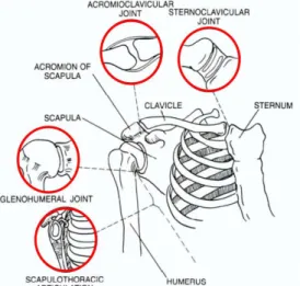
The shoulder complex is composed of three bones (humerus, scapula and clavicle) and four joints as seen in Figure 1. The joints are not very congruent, and thus the shoulder complex has got a great degree of mobility, which can compromise its stability.
The aim of this work is to propose a robust approach, which allows the use of a VICON system as a Dynamic 3D Shape Tracking Device (DSTD) – see endnotes. This novel approach is compared with two methods of the literature (Geometrical Method [1] and Point Cluster Method [2]). Our first goal is to emphasize that a shape-based analysis gives rise to divergent conclusions for some motion components when applied to the scapula in the shoulder complex.
This paper is divided into five parts. After this introduction, section 2 presents a state of the art of motion
Manuscript received April 16, 2007 – revised June 19, 2007. This work was supported by a grant of the Brittany Region.
The authors are with INSERM, U650, Brest, F-29200 France (e-mail: [email protected]).
C. Schwartz, J.J. Jacq and V. Burdin are also with GET/ENST Bretagne, Brest, F-29200 France.
C.Schwartz and M.Lempereur are also with Université de Bretagne Occidentale, Brest, F-29200 France
O. Rémy-Néris is also with CHU Brest, Service de médecine physique et de réadaptation, Brest, F-29200 France.
analysis. Following a summary of the acquisition protocol, section 3 gives the main lines of the proposed method based on the Iterative Median Closest Point algorithm (IMCP) [3] for estimating the motion. In section 4, first results are presented and compared with two other methods of the literature. These first results are discussed in section 5.
Fig. 1. Shoulder complex: bones and joints.
II. MOTION ANALYSIS
A. Usual tracking systems
Motion studies can be divided into two groups: static or quasi-static acquisitions, and dynamic acquisitions.
The main static acquisitions were carried out with X-ray photogrammetry [4], with palpation [5] and with open [6] or closed [7] configuration MRI. The main drawback of these methods is the limited number of positions that can be acquired. Thus, they will not be considered in this paper, which will focus on a dynamic realistic study to understand the shoulder movements.
Dynamic studies use opto-electronic markers [8] or magnetic sensors [9]. Their main advantage is the possibility to acquire nearly all sorts of motions under dynamic conditions. Unfortunately, the measures are not directly linked to the bones movement but to the skin deformation. Consequently, some disadvantages can be underlined:
• Skin deformation causes relative displacements between the markers and the underlying bone. Matsui [10] measured skin movement errors up to 85 mm for the scapula. In addition, the error value is linked to the nature and range of the motion.
• The placement of landmarks depends on the manipulator. Williams [11] reported mean intra and inter-observer placement errors of about 15 mm.
Shoulder motion analysis using simultaneous skin shape registration
C. Schwartz, Student, M. Lempereur, V. Burdin, Member, J.J. Jacq, Member, O. Rémy-Néris, IEEE
In spite of good spatial and temporal accuracy, the skin movement errors need an information processing. Several approaches have been developed to correct the marker positions and so, to reduce the influence of skin movements and deformations [12].
B. Data processing
Veldpaus [13] and Soderkvist [14] proposed to minimize the difference between the measured and ideal positions of these markers. Another method, proposed by Chèze [15] and named “solidification” computes the movement of the solid, which is the most compatible with the marker trajectories. The solid corresponds to three markers which best represent the bone segment. Proposed by Lu [16] for the lower limb and applied by Roux [17] to the upper limb, the global optimization method corrects the orientation of the bone whenever relevant joint constraints are a priori available.
In order to correct the skin deformation, other approaches are based on the use of marker cluster rather than individual markers. In this paper, we will compare our new approach with the Point Cluster Method (PCM), proposed by Andriacchi [2] [18] for the lower limb. The PCM attempts to minimize the skin motion artifacts by an optimal and iterative weighting of the markers according to their degree of deformation. The “weight” of each marker is evaluated in order to minimize the variation of the eigenvalues of the inertia matrix of the marker cluster.
III. MATERIALS AND METHODS
A. Protocol
In this study, the shoulder motion is measured with a VICON opto-electronic system composed of seven infrared video cameras MX13 (1.3 MPixels). The acquisition frequency is equal to 120 Hz. In order to compare the different methods, we simultaneously place the markers for each of them in the same acquisition. Skeletal landmarks are 14 mm markers whereas 4 mm markers are used for clusters. The subject performs five flexions of the arm (in sagittal plane) from rest position to approximately 150° extension. The subject lies flat on his belly. The lying position was chosen for later comparison with MRI acquisitions – this work is not presented in this paper.
The standard geometrical method uses skeletal landmarks. It involves markers positioned following the International Society of Biomechanics (ISB) recommendations [1]. Three markers are needed to create a coordinate system. The ISB proposed three skeletal landmarks for the scapula and four others for the thorax (Table 1 and Figure 2). AA, TS and AI are the chosen bone landmarks of the scapula for this study [1]. The ISB method uses these three markers to create a local coordinate system on the scapula. The registration of this system is a basic geometric way to estimate its motion [19].
While operating through this usual protocol, gaining access to a large marker cluster becomes the main requirement of the IMCP algorithm. Within our first
experiments, a cluster of 123 markers is used in order to cover the entire surface of the consecutive locations of the scapula. To our knowledge, such a large cluster has not been reported yet in the literature.
Bone segments Skeletal landmarks
TS Trigonum Spinae Scapulae AI Angulus Inferior Scapula
AA Angulus Acromialis
C7 Processus Spinosus of the 7th cervical vertebra
T8 Processus Spinosus of the 8th thoracic vertebra
IJ Deepest point of Incisura Jugularis Thorax
PX Processus Xiphoideux
Table 1. Skeletal landmarks of the thorax and the scapula.
B. Motion estimation from dynamics of the skin shape
As stated before, the main idea is to focus on the instantaneous skin shape. Thus, the available marker cluster must be modeled as a rough point sampling of its embedding continuous surface. The primary information becomes the shape morphology. Upon noise cleanup, the raw marker cluster can be seen as describing the seeding nodes of a 2D parameterization of the skin shape. Thus, the marker locations are no more taken into account as the primary measurements. This relaxes the requirement for a marker to account for a specific location of the underlying bone along the full movement. As this may cancel out the effects of some tangent drifts of its location w.r.t. movement phases, we expect to provide an approach less vulnerable to skin shifts than usual marker-based approaches.
Thus, we are making use of the VICON apparatus as a shape-tracking device – we are not tracking a marker cluster. Conversely, within each time-step, we are focusing on the current polyhedral shape embedding the markers set. As this implies canceling out markers as individual 0D geometric objects, this makes a world of difference. Indeed, the IMCP [20–21,3] approach gives us means to make use of a VICON system as a Dynamic 3D Shape Tracking Device (DSTD). Therefore, we hypothesize that being able to globally and simultaneously track rigid sub-regions of the skin evolving shape will
(i) lessen skin-shift-related biases,
(ii) give a better accuracy w.r.t. kinematic measurements, (iii) give rise to a better understanding of some insides
activities linked to the soft tissues.
The previous last point (iii) is related to the availability of the median consensus shape – an intrinsic output of the IMCP algorithm. Indeed, the IMCP is a robust, simultaneous and multi-object extension of the classic algorithm of registration ICP (Iterative Closest Point). The algorithm operates through simultaneous registration of all geometrical instances on a virtual instance accounting for their median consensus. In essence, this method exploits both the spatial and temporal redundancies of the available instance set. Technical descriptions of the IMCP are available elsewhere [20–21]. A short introduction, as well as another application, can be found in [3].
IV. RESULTS
Homogeneous matrices are used to determine the rotational matrix of the scapula with respect to the thorax. Scapular rotations are represented using a standard Euler angle sequence [1] of external/internal rotation (Y axis), upward/downward rotation (X axis) and posterior/anterior tilting (Z axis). The distal local coordinate system (Figure 2a) and the proximal local coordinate system (Figure 2b) are created following the ISB recommendations [1].
Fig. 2. Skeletal landmarks and coordinate systems of the scapula (Fig. 2a) and of the thorax (Fig. 2b).
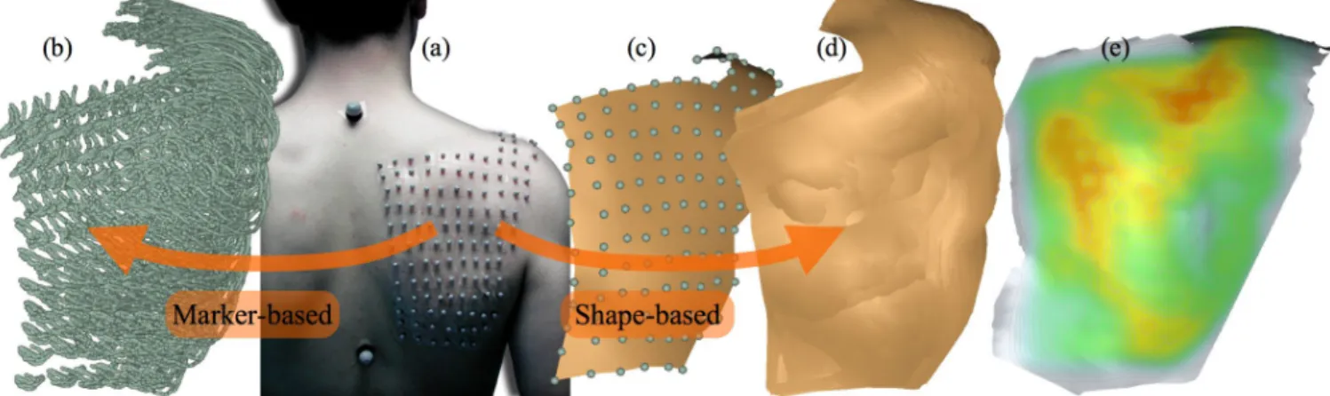
Figure 3 depicts the processing of three flexion-extension periods by the IMCP algorithm. In addition to accurate kinematics measurement extracted from the 1200 available shape instances (Fig. 3.d) – whose results are discussed below – the algorithm synthesizes their median consensus shape (Fig. 3.e). This shape is drawn within the lying position depicted by Fig. 3.a. Its color texture aims at underlying high consensus level. This rating-level expresses how-well a region accounts for a rigid-like kinematics along the full sequence. We make the assumption that high consensus regions can be interpreted as fuzzy casts of some underlying bone ridges. As a matter of fact, one can see that two standard ISB anatomical landmarks (TS and AI – see Fig. 2.a) seem to be in good accordance with the consensus level map. However, the main consensus cluster does account for the usual anatomical landmark AA.
The same subject motion was processed by all the three methods. For an easier comparison, the reference posture was defined as the first frame of the motion. Thus, all calculated rotations start from 0°. The results issued from the IMCP are presented in Figure 4. For antero/posterior tilt, the IMCP measures a greater rotation. Measured amplitudes are respectively 22°, 12° and 7° for IMCP, PCM and ISB. For upward/downward and internal/external rotations, all three methods give similar results. Upward/downward rotation mean amplitude is 26° and internal/external mean rotation amplitude is 10°.
V. DISCUSSION
Although an extensive assessment of the measurements is not the primary goal of this first step of our work, one must emphasize here that no ground truth exists in such studies. Thus, in spite of efforts to standardize acquisition procedures, it remains difficult to compare our results with the literature. Indeed, differences in the protocols are not negligible. One of the few validation techniques makes use of pins directly drilled into the scapula. Therefore, this method is not largely widespread since it requires invasive manipulations. Moreover, the interaction of the pins and the muscles may constrain its natural motion. McClure [22] uses an electro-magnetic sensor fixed on pins to evaluate the scapula motion. He measures 31° antero/posterior tilt, 46° upward/downward rotation and 26° internal/external rotation. Unfortunately, this work cannot be easily compared to ours. Indeed, McClure’s subject was standing whereas ours was lying. Moreover, De Groot [5] shows that inter-subject variability of the motion is equal to 5-10°. Meanwhile, the ISB and the PCM seems to under-estimate the real motion of the scapula. Conversely, the IMCP presents encouraging results around the antero/posterior axis. Indeed, the use of a large marker cluster allows covering the scapula from the inferior angle to the acromion. Thus, the IMCP takes takes full advantage of temporal and morphological redundancies. Unlike markers-based
Fig. 3. Processing of three flexion-extension periods by the IMCP algorithm. The data acquisitions convey up to 1200 instances dispatched over 10 sec. Unlike markers-based tracking (b), an interpolating surface (c) is built for each instance locations. Upon simultaneous registrations of the set of surfaces (d), the colors of the median skin shape (e) account for the IMCP consensus level – white means zero consensus (i.e., unreliable parts) whereas red means maxima of the consensus. Views (b) and (d) depicts the whole sweep in thorax coordinate system. The consensus shape (e) is drawn at rest location (t = 0).
Fig. 4 Rotations of the scapula.relative to the thorax Fig. 4a: Internal/External rotation. Fig. 4b: Anterior/Posterior tilt. Fig. 4c: Upward/Downward rotation.
approaches (e.g., PCM), it does not consider pieces of data as uncorrelated.
It should also be noticed that the few markers on the thorax, which are used to create the proximal coordinate system, also undergo errors due to skin artifacts. This may cause additional errors, when computing the Euler angles from the homogenous matrices.
VI. CONCLUSION
This paper proposes to robustly track the skin shape to recover accurate information about the underlying bone motion. Current applications address the scapula kinematics. The motion estimates are compared to a geometric method (ISB) and a point cluster method (PCM). The results show important differences between the methods. As expected, the IMCP computes greater amplitude. A validation study, by mean of palpations as well as 3D MRI, needs now being carried out in order to corroborate this new but still promising approach. Moreover, a closer examination of the information embedded in the consensus skin shape should bring out new knowledge about soft tissue dynamics.
REFERENCES
[1] Wu G. et al. “ISB recommendation on definitions of joint coordinate systems of various joints for the reporting of human joint motion – Part II: shoulder, elbow, wrist and hand,” Journal of Biomechanics, Vol. 38, p. 981-992, 2005.
[2] T.P. Andriacchi, E.J. Alexander, M.K. Toney, C. Dyrby, and J. Sum, “A point cluster method for in vivo motion analysis: applied to a study of the knee kinematics,” Journal of Biomechanical Engineering, Vol. 120, p. 743-749, 1998.
[3] T. Cresson, J.J. Jacq, V. Burdin, and C. Roux “Performing accurate rigid kinematics measurements from 3D in vivo image sequences through median consensus simultaneous registration,” Proc. of IEEE Engineering in Medicine and Biology Conf., Shanghai, Sept. 2005. [4] C. Högfors, B. Peterson, G. Sigholm, and P. Herberts, “Biomechanical
model of the human shoulder – II. The shoulder rhythm,” J. Biomechanics, Vol. 24, p. 699-709, 1991.
[5] J.H. de Groot, “The variability of shoulder motions recorded by means of palpation,” Clinical Biomechanics, Vol. 12, No. 7/8, p. 461-472, 1997.
[6] C.F. Beaulieu, et al. “Glenohumeral relationships during physiological shoulder motion and stress testing: initial experiment with open MR imaging and active imaging-plane registration,” Radiology, Vol. 212, p. 699-705, 1999.
[7] R.C. Rhoad, et al. “A new in vivo technique for three-dimensional shoulder kinematics analysis,” Skeletal Radiol. Vol. 27, p. 92-97, 1998. [8] S.S. Rao, E.L. Bontrager, J.K. Gronley, C.J. Newsam, and J. Perry, “Three-dimensional kinematics of wheel-chair propulsion,” IEEE Trans. Rehab. Engng, Vol. 4, pp. 152-160, 1996.
[9] C.G.M. Meskers, H. Fraterman, F.C.T van der Helm, H.M. Vermeulen, and P.M. Rozing, “ Calibration of the “Flock of Birds” electromagnetic tracking device and its application in shoulder motion studies,” Journal of Biomechanics, Vol. 32, pp. 629-633, 1999.
[10] K. Matsui, K. Shimada, P.D Andrew, “Deviation of skin marker from bone target during movement of the scapula,” J Orthop Sci, Vol. 11, pp. 180-184, 2006.
[11] J.R. Williams, “Some aspects of the biomechanics of the elbow joint related to prosthetic design,” DM thesis, Oxford University, Oxford, 1996.
[12] A. Leardini, L. Chiari, U.D. Croce, and A. Cappozzo, ”Human movement analysis using stereophotogrammetry Part 3. Soft tissue artefact assessment and compensation,” Gait and Posture, Vol. 21, p. 212-225, 2005.
[13] F.E. Veldpaus, H.J. Woltring, and L.J.M.G. Dortmans, “A least-squares algorithm for the equiform transformation from spatial co-ordinates,” Journal of Biomechanics, Vol. 21, p. 45-55, 1988. [14] I. Soderkvist, and P.-A. Wedin, “Determining the movements of the
skeleton using well-configured markers,” Journal of Biomechanics, Vol. 26, p. 1473-1477, 1993.
[15] L. Chèze, B.J. Fregly, and J. Dimnet, “A solidification procedure to facilitate kinematic analyses based on video system data,” Journal of Biomechanics, Vol. 28, p. 879-884, 1995
[16] T.W. Lu, and J.J. O’Connor, “Bone position estimation from skin marker co-ordinates using global optimisation with joint constraints,” Journal of Biomechanics, Vol. 32, p. 129-134, 1999.
[17] E. Roux, S. Bouilland, A.-P. Godillon-Maquinghen, and D. Bouttens “Evaluation of the global optimisation method within the upper limb kinematics analysis,” Journal of Biomechanics, Vol. 35, p. 1279-1283, 2002.
[18] E.J. Alexander, and T.P. Andriacchi, “Correcting for deformation in skin-based marker systems,” Journal of Biomechanics, Vol. 34, pp. 355-361, 2001.
[19] C. Schwartz, M. Lempereur, V. Burdin, J.J. Jacq, O.Rémy-Néris, “Méthode d’analyse du mouvement par utilisation de nappes de marqueurs,” TAIMA Conference, Hammamet, Tunisia, 2007.
[20] J.J. Jacq, “Performing Accurate Joint Kinematics from 3D in vivo Image Sequences through Median Consensus Simultaneous Registration”, Internal report, LaTIM U650, March 23, 2005, 65 p. [21] J.J. Jacq, T. Cresson, V. Burdin, C. Roux, "Performing Accurate Joint
Kinematics from 3D in vivo Image Sequences through Consensus-Driven Simultaneous Registration", IEEE Trans. on Biomedical Engineering (In press)
[22] P.W. McClure, L.A. Michener, and B.J. Sennett, “Direct 3-dimentional measurement of scapular kinematics during dynamic movements in vivo,” J Shoulder Elbow Surg, Vol. 10, pp. 269-77, 2001.
Endnotes—Here, through the acronym DSTD, we denote a class of marker-less device (1) able to undergo video sampling rate (i.e., rates better-or-equal to 60 Hz) while performing (2) dense (3) regular and (4) simultaneous sampling of an evolving 3D shape with (5) an accuracy compatible with common medical requirements (typ. better-or-equal to 1 mm with distances < 2 m). Our VICON-based hardware emulation mostly fulfills these main requirements (1:120Hz; 3; 4; 5:±1mm). However, for a better adequacy, the markers layer remains to be densified.