Science Arts & Métiers (SAM)
is an open access repository that collects the work of Arts et Métiers Institute of
Technology researchers and makes it freely available over the web where possible.
This is an author-deposited version published in: https://sam.ensam.eu Handle ID: .http://hdl.handle.net/10985/10070
To cite this version :
Jorge SALGUERO, Moises BATISTA, Madalina CALAMAZ, Franck GIROT, Mariano MARCOS -Cutting Forces Parametric Model for the Dry High Speed Contour Milling of Aerospace Aluminium Alloys - Procedia Engineering - Vol. 63, p.735-742 - 2013
Any correspondence concerning this service should be sent to the repository Administrator : archiveouverte@ensam.eu
Procedia Engineering 63 ( 2013 ) 735 – 742
1877-7058 © 2013 The Authors. Published by Elsevier Ltd.
Selection and peer-review under responsibility of Universidad de Zaragoza, Dpto Ing Diseño y Fabricacion doi: 10.1016/j.proeng.2013.08.215
ScienceDirect
The Manufacturing Engineering Society International Conference, MESIC 2013
Cutting Forces Parametric Model for the Dry High Speed Contour
Milling of Aerospace Aluminium Alloys
J. Salguero
a,*, M. Batista
a, M. Calamaz
b, F. Girot
b, M. Marcos
aaMechanical Engineering and Industrial Design Department, University of Cadiz, c/ Chile 1, Cadiz E-11002, Spain
bEcole National Superieure d´Arts et Métiers (ENSAM)-ParisTech, I2M-MPI Dept. Esplanade des Arts et Métiers, 33405 Talence (FRANCE).
Abstract
Cutting forces is one of the most important outputs in material removal machining processes. Their values depend on a large number of parameters, such as the cutting tool material and geometry, the workpiece material or the cutting parameters, among others. In this paper, cutting forces behavior have been analyzed as a function of feedrate and cutting speed, for the high-speed peripheral milling of UNS A92024-T3 (Al-Cu) stacks. This alloy is widely used in the manufacturing process of aircraft structural elements. From this analysis, different parametric models have been adjusted to experimental data, establishing Fn=f(fz,V) relationships that allow an approximation to the values of force components for machining conditions dependent on those variables.
© 2013 The Authors. Published by Elsevier Ltd.
Selection and peer-review under responsibility of Universidad de Zaragoza, Dpto Ing Diseño y Fabricacion.
Keywords: Cutting force; parametric model; high speed milling; dry machining; aluminium.
1. Introduction
A machining process is strongly dependent on a high number of variables and parameters (input), such as, among others, cutting speed, feed, depth of cut, tool material and geometry, lubrication and cooling, which has a considerable influence on the worked pieces quality. This influence is usually reflected in other variables and parameters (output), such as, among others, forces, temperature, tool life and tool wear. Cutting force is one of the most relevant output variables since the information that can provide for the machining process evaluation, Crrilero
* Corresponding author. E-mail address: jorge.salguero@uca.es
© 2013 The Authors. Published by Elsevier Ltd.
736 J. Salguero et al. / Procedia Engineering 63 ( 2013 ) 735 – 742
and Marcos (1996). This owes to that cutting forces depends on all the input variables and parameters; so, according to Axinte et al. (2011) and Sanchez et al. (2003), it can be written:
F = f(w1,..., wq, f, V, p, tg (1)
In this equation, wi are the parameter related to the material to be machined; tgi and tmh are the parameters related to tool material and geometry; LR represents the lubrication and cooling conditions; finally, ri are variables associated with the machining process and the rest of the cutting conditions.
Equation (1) is hardly controllable since the high number of variables that tkae place in it. However, if some pre-established conditions, such as lubrication, tool and cutting depth, are fixed for a specific process of a specific material, this equation can be reduced to only two variables: feed (f) and cutting speed (V), making easier its control. So, in this case, equation (1) is transformed to:
F= f(f,V) (2)
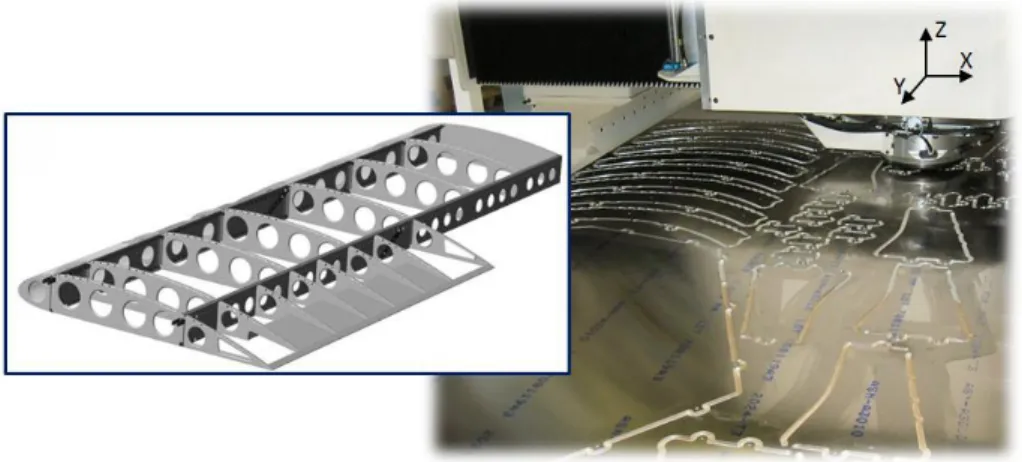
High Speed Contour Milling (HSCM) is one of the machining processes in which cutting forces can be expressed by equation (1) or, more simply, by equation (2). HSCM is widely used in aeronautical industry for producing structural elements, Figure 1.
Fig. 1. Typical aeronautical structural elements made by HSCM
HSCM is habitually applied to high dimensions Aluminium sheet stacks in order to maximize the manufacturing process productivity. HSCM is commonly performed in gantry type machines with a treading head, which presses the sheets avoiding the axial displacement when the head is moving in the XY plane at a constant depth of cut. Later, the contoured plane pre-forms are plastically shaped and finished in a previous stage to assembly.
Empiric-experimental parametric models are commonly obtained from the mathematical adjustment of experimental data to pre-established math functions. These models are useful for approximating and predicting the output variables when input variables change. So, in particular, parametric exponential models have shown a good adjustment for macrogeometrical deviations, such as straightness and parallelism, Sanchez-Sola et al. (2012), in the dry turning of Aluminium alloys. However, according to Salguero et al. (2011) and Campatelli et al. (2012), in the same processes, potential models present the best adjustment for other output variables such as roughness or cutting forces.
In this work, a methodology for the study of the cutting forces in HSCM processes of UNS A92024-T3 (Al-Cu) stacks is presented. Additionally, a first proposal of cutting speed (V) and feed per tooth (fz) based parametric
models for experimental components of cutting force, F(fz,V). These models have been developed from the individual models extracted from the marginal adjustment of the cutting force componets to each one of the input variables: F(fz) and F (V).
2. Experimental work
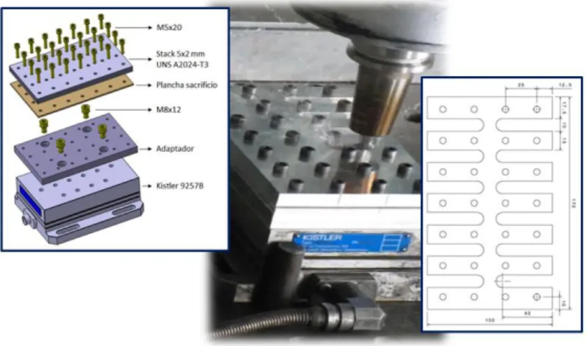
The industrial process of High Speed Contour Milling of sheet stacks is hardly reproducible at a lab scale. On the other hand, it has not been possible to place a dynamometer in the Aeronautical Shop-floor where the HSCM is commonly carried out. Because of this, HSCM tests have been carried out in a Fatronik Hera machining Center equipped with a Siemens Sinumerik 840D Numerical Control. 10 mm wide and 40 mm length grooves on five 170x100x2 mm3 UNS A92024-T3 sheet stacks were performed in this CNC Center.
Stacks were prepared for being coupled to a Kistler 9257B dynamometric table through the mechanical joint of stacks to an adapter, so reducing axial displacements and simulating the effect of a threader head, Figure 2.
Fig. 2. Some details of the experimental configuration
Stacks were prepared for being coupled to a Kistler 9257B dynamometric table through the mechanical joint of stacks to an adapter, so reducing axial displacements and simulating the effect of a threader head, Figure 2.
A COINDU® (ref. D10.63) WC-10Co, K30, two teeth ( =17º, =20º) mill was used in the milling tests. Mill
diameter was 10 mm and the mill helix angle was 30º. Mill was coupled to a thermal contraction HSK 50 tool-holder. On the other hand, tests were realized in absence of cutting fluids, favoring so the increase of the environmental performance of the machining process. Cutting parameters applied have been included in Table 1.
Table 1. Machining parameters values applied to the FPAV process V (m/min) S (rev/min) 503 16000 565 18000 628 20000 691 22000 754 24000 817 26000 fz (mm) 0,035 0,050 0,065 0,080
Cutting forces have been acquired at an acquisition frequency of 20 kHz, using a National Instruments DAQCard-6062E® board and a BNC-2110 multiplexor. Acquisition and translation of the triaxial cutting force
738 J. Salguero et al. / Procedia Engineering 63 ( 2013 ) 735 – 742
3. Results and Discussions
Figure 3 plots typical cutting force orthogonal component records. Two zones can be distinguished in this figure. First of them corresponds to the initial input drilling process, conducted at a half of the programmed feed (notice that Fz has a similar behavior in the drilling process of each sheet of the stack). Second zone is the corresponding to the 40 mm grooving process and the tool way out. The analysis has been centered in this pseudo-stationary zone, where the average value of each component has been calculated, Figure 3.
Fig. 3. Typical cutting force records (fff =0,035mm, V=503 m/min). Evaluation and analysis zone has been framedz
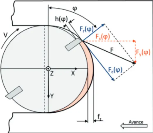
In the framed zone of the Figure 3, FX shows a behavior near to sinusoidal, characteristic of the milling
processes, with positive values when the tool spin-turn angle ( ) is between 0 and 2 (milling in opposition), and/2 negative values when iss between /22 and (milling in concordance), Figure 4. F( Ycomponent has positive values
due to the reference system that has been used, own of the dynamometer. On the other hand, FZnegative values
indicate that the positive helix angle of the tool generates axial forces, which trends to get up the sheets and to provoke separations between the interfaces in a form approximately periodic during the process. It must be also noticed that, as it can be expected, FZvalues are much lower than those corresponding to FXand FY. Additionally,
it can be stated that the spring-back in the material compressive direction is the responsible of the gap between the maximum and minimum values of FX and FY components. In parallel, the gap in FZ can be associated to the
vertical response of the sheets that configure the stack, and that do not respond to an average distribution as FXand
FY.
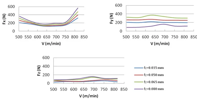
Figure 5 plots the cutting force orthogonal components average values as a function of the cutting speeds for each feed of tooth applied.
Fig. 5. Evolution of the components of the cutting force as a function of the cutting speed for different values of fZ
Looking at Figure 5, it can be noticed that FN(V) curves (N=X,Y,Z) show a light displacement with fz. On the
other hand, FN(fz) curves show a tendency to increase for each cutting speed. According to Campatelli et al. (2012)
and Carrilero et al. (1998), a potential model can be proposed for the marginal distributions of the cutting force components as functions of feed per tooth:
FN = a fzb (3)
However, FN(V) is different depending on the cutting force component. In effect, for FY and FZ components,
some stability can be appreciated with only a light increasing. According to Campatelli et al. (2012) and Carrilero et al. (1998), it allows proposing potentials models as the equation (3). Thus:
FN = a Vb (4)
In this way, FY and FZ can be modeled as follows:
FN = a Vb fzc (5)
Coefficient and exponent values, a, b and c, can be calculated by linearizing Equation (5) by making a translation to logarithmic scale:
740 J. Salguero et al. / Procedia Engineering 63 ( 2013 ) 735 – 742
This equation corresponds to a plane in the log (FN) - log (fz) - log (V) space. A multilinear regression can be applied for determining the a, b and c values:
Fn´= a´ + b X + c Y (7)
Table 2 includes the values of the independent terms of the parametric model.
Table 2. Coefficient and exponents of the potential model for FY and FZ
a b c R2
FY (N) 5751,64 -0,11 0,78 0,95
FZ (N) 7,57 0,86 1,13 0,82
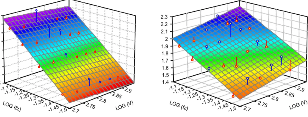
Notice the good adjustment and the good approximation of the model to the experimental data, Figure 6.
2.7 2.75 2.8 2.85 2.9 LOG (V) -1.5 -1.45 -1.4 -1.35 -1.3 -1.25 -1.2 -1.15 -1.1 LOG (fz) 2.25 2.3 2.35 2.4 2.45 2.5 2.55 2.6 2.65 2.7 2.75 2.8 2.85 2.9 LOG (V) -1.5 -1.45 -1.4 -1.35 -1.3 -1.25 -1.2 -1.15 -1.1 LOG (fz) 1.4 1.5 1.6 1.7 1.8 1.9 2 2.1 2.2 2.3
Fig. 6. Regression planes log(FN) - log(fz) - log(V) for FY and FZ
On the other hand, the evolution of FX as a function of V is noticeably different to those observed for FY and FZ,
Figure 5. It can be noticed that FX has a minimum value extended in a range of values of V. This fact is
characteristic of HSCM and it allows defining the cutting speed range where FX is minimal for each feed per tooth
value. Firstly, a bi-parabolic convolution model could be considered. In order to simplify this model for taking an unique theoretical minimum, a parabolic model can be proposed:
FX = =a+bV+cV2 (8)
Coefficients and exponents of the marginal models FX(fz), Eq. (4), and FX(V), Eq. (8) are included in Tables 3
and 4, respectively.
Table 3. Adjustment values for marginal FX = a fzb
V(m/min)
503 565 628 691 754 817
a 2072,50 644,50 426,39 819,41 770,33 3067,43
b 1,45 2,49 2,54 1,71 2,02 1,47
Table 4. Adjustment values for marginal FX=a+bV+cV2 fz (mmn) 0,035 0,050 0,065 0,080 a 2591,4 3496,8 4362,5 5201,5 b -7,75 -10,50 -13,17 -15,77 c 0,0061 0,0082 0,0103 0,0123 R2 0,8894 0,9112 0,9238 0,9208
The good adjustment of the values included in Tables 3 and 4 allows proposing a combined parabolic-potential model:
FX = (a+bV+cV2) fzd (9)
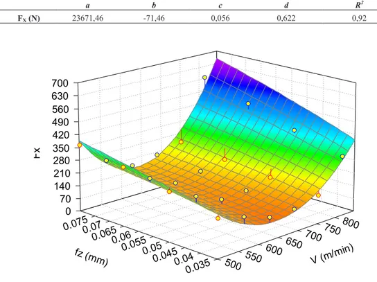
Table 5 includes the values of the coefficients and exponent of the combined model of Equation (9). Notice the good adjustment of the model to the experimental data.
Table 5. Adjustment values for the combined model of the Equation (9).
a b c d R2 FX (N) 23671,46 -71,46 0,056 0,622 0,92 500 550 600 650 700750 800 V (m/min ) 0.035 0.04 0.045 0.05 0.055 0.06 0.065 0.07 0.075 fz (mm ) 0 70 140 210 280 350 420 490 560 630 700 F x
Fig. 7. Coons adjustment surface FX(fz,V)
4. Conclusions
This paper has reported on the results of a study of the influence of cutting speed and feed per tooth on the orthogonal components of cutting force acquired in the High Speed Contour Milling processes of Al-Cu sheets stacks
742 J. Salguero et al. / Procedia Engineering 63 ( 2013 ) 735 – 742
Z cutting force component, FZ, has shown a value lower than the recorded for FX and FY. This has been
associated with the dependence on the stacked sheets separation. On the other hand, FX and FY show a periodic
behavior related to the milling process. However, the maximum and minimum values of both components show a gap associated to the reaction of the material to compression stress in Y.
Average values of the absolute records of the components have been used for studying the influence of the cutting parameters. Results obtained has allowed proposing marginal potential models FX,Y,Z (fz) and FY,Z(V). So,
FY,Z(fz,V) responds to a combined potential model.
On the other hand, FX(V) is well adjusted to a parabolic model. Thus, a combined potential-parabolic model can be proposed for FX(fz,V).
All the models have preseted a good adjustment to the experimental data.
Acknowledgements
This work has received financial support by the Spanish Government (Project DPI2011-29019), from the European Union (FEDER/FSE) and from the Andalusian Government.
References
Axinte, D. A., Belluco, W. De Chiffre, L,.2011. Evaluation of cutting force uncertainty components in turning. International Journal of Machine Tool & Manufacture, 41, pp. 719-730.
Campatelli, G. Scippa. A., 2012, Prediction of milling cutting force coefficients for Aluminum 6082-T4. Procedia CIRP, 1, pp. 563 568. Carrilero, M.S., Marcos, M., Álvarez, M., Sánchez, V.M., 1998. Evaluación de la calidad superficial de piezas mecanizadas a partir del análisis
de la fuerza de corte. Revista de Metalurgia, 34, pp. 27-31.
Carrilero, M.S., Marcos, M.. 1996. On the machinability of aluminium and aluminium alloys. Journal of Mechanical Behaviour of Materials, 7(3), pp. 179-193.
Salguero J. et al., 2011, Roughness prediction models for tangential cutting forces in the dry turning of Al-Cu alloys. Proc. of AMPT 2011: Int. Conf. on Advances in Materials and Processing Technologies. Istanbul, Turkey.
Sánchez, J.M., Marcos, M., Sebastián, M.A., Sánchez, M., González, J.M., 2003. Modelo paramétrico de la fuerza de corte para el torneado de la aleación AA2024. Boletín de la Sociedad Española de Cerámica y Vidrio, 43(2), pp. 179-181.
Sánchez-Sola, J.M., et al., 2012. Cutting speed-feed based parametric model for macro-geometrical deviations in the dry turning of UNS A92024 Al-Cu alloys. Key Engineering Materials, 504-506, pp. 1311-1316.