Science Arts & Métiers (SAM)
is an open access repository that collects the work of Arts et Métiers Institute of Technology researchers and makes it freely available over the web where possible.
This is an author-deposited version published in: https://sam.ensam.eu Handle ID: .http://hdl.handle.net/10985/19122
To cite this version :
Simon GORECKI, Judicael RIBAULT, Gregory ZACHAREWICZ, Yves DUCQ, Nicolas PERRY -Risk management and distributed simulation in Papyrus tool for decision making in industrial context - Computers & Industrial Engineering - Vol. 137, p.106039 - 2019
Risk management and Distributed Simulation in Papyrus tool for Decision
Making in industrial context
Simon Gorecki*, Judicael Ribault*, Gregory Zacharewicz**, Yves Ducq*, Nicolas Perry***
*Univ. Bordeaux, CNRS, IMS, UMR 5218, 33405 Talence, France {firstname.lastname}@u-bordeaux.fr **LG2IP lab. IMT – Mines Ales, [email protected],
***Arts et Métiers ParisTech ENSAM of Bordeaux, [email protected]
ABSTRACT
Modeling and Simulation (M&S) are important steps in the design of industrial systems and production plants. They help in anticipating and understanding these complex systems in order to make decisions about strategic implementations before effective development. Once the models are satisfyingly built, namely they correctly reflect the system, the simulation can offer many behavioral information to the user. In this paper, we are proposing to integrate risk management, hazard generation, and complexity issues in process modeling with data coming from industrial context: polar power plant design. In this context, risks and hazards must be modeled, but are too large to be in the main model. For this purpose, the paper presents some extensions to the modeling and simulation open source tool: Papyrus. This proposition consists in developing the Papyrus features for outsourcing risks and hazards out of the model, exporting simulation’s data in different components for decision making, and implementing distributed simulation mechanisms for dealing with reusability, and interoperability of components.
Keywords: Model Driven Architecture; HLA; Papyrus; Simulation; Risk management.
1. INTRODUCTION
In industry, risk management was becoming a huge challenge facing on one hand the increasing complexity of manufacturing systems and on the other hand the evolution of legal context which force companies to prove their maturity in this domain as recommended in the new ISO 9001 standard. Moreover, the design and steering of complex systems requires Modeling & Simulation (M&S) steps to represent behaviors and interactions in and between the systems.
As technologies are growing, complexity also increase and makes systems more and more difficult to model and simulate. In M&S, Modeling allow to represent any complex system according to a standard. Once the modeling phase is completed, Simulation of these systems will allow to virtually design our subject to anticipate and avoid problems in future. This growing complexity can be handle by simulating risks, hazards, and taking threat in account during the modeling phase.
Once the model is designed, the performance indicators and the dashboard can be setup for helping the user to define the better choice in a given situation. Many works have been done in project’s risk
management and have proven this fact (Altuhhova et al., 2013; Better et al., 2008). All these disturbances can impact the process of decision making which implies the need of simulation tools as a decision-making tool.
According to (Barki et al., 1993), the notion of risks and hazards are “the uncertainty surrounding a project and the magnitude of potential loss associated with project failure” or the “Probability and consequences of different outcome scenarios associated with a hazard” according to (Paté-Cornell, 2002). In this paper, risks, hazards and complexity must be considered separately even if risks and hazards are linked, a risk being able to generate a hazard and vice versa. Hazards are present at every steps of the process. Hence, they must be relocated outside of the model. Then, complexity must be relocated by Distributed Simulation (DS). We will use this concept in an industrial context providing the application case with Papyrus tool.
Papyrus, an open source UML / SysML modeler, provides a tool to users and developers to specify UML models and then to execute them with the Foundation UML Subset (fUML) standard (OMG Publication 2018). Papyrus is already used by our partner company to model and simulate the production of solar power plant. This software is used for its user-friendly modeling and simulation features in terms of the fUML standard. Specific behaviors can also be described according to the UML profile. Those profiles can be considered during the simulation run through the Moka execution engine. Modeling all the risks and hazards impacts implied by the complexity growth would make the initial model unreadable (Gorecki et al., 2018). For this reason, every issue in this paper is solved by adding a new UML profile and Moka extensions over Papyrus and Moka implementations. Helping the users in the decision-making process will be done by developing a specific Moka extension. This layer over the Moka execution engine is able to export the simulation indicators and provide a customizable dashboard. The users can select important variables in the model which must be readable in the dashboard. Later, after the simulation ending, the users can access them through different graphs.
Risks and hazards simulation are an important point in our context. Our case study consists in models disturbed by a great number of hazards. Hazards and risks are various, can influence main model in every task. Hence the need of “hazard injection”. The main goal consists in having a main model, without risk management, connected to a risks management scenario which influence the model at the simulation time.
The injection of hazards in the model is outsourced with a second UML profile and a specific Moka extension. This UML profile contains a unique ID associated to each task which must be affected by hazards. During the execution process, a specific Moka extension alters the execution of these tasks thanks to a database containing risks equations.
Finally, the complexity is treated by managing Papyrus instances as DS components to allow the users and developers to deal with complexity and time constraints. More specifically, the goal is to implement mechanisms of synchronization points in several Moka instances. This complex problem implies defining a synchronization, communication algorithm which is not defined by the Functional Mock-up Interface (FMI) Co-Simulation standard.
To solve the time related issues in distributed context, the use of High Level Architecture (HLA) standard (IEEE Computer Society, 2010a, 2010b, 2003) offered as one of the most used standard in DS. In HLA, the Run Time Infrastructure (RTI) can solve interoperability issues between components, provide communication mechanism and time management.
The rest of the paper is structured as follows. Section 2 provides an introduction to essential background knowledge on the domain. Section 3 presents the state of art of the research efforts to address the risks issues, hazards and complexity management in M&S. Section 4 presents our proposition to overcome the above-mentioned issues. A case study provided by our partner company is presented in section 5. Finally, conclusion and discussion are done in section 6.
2. MATERIAL AND METHODS
2.1 Risks and hazards management
Risks and hazards are polysemous subjects and can have many definitions.
In the connection of danger management, the literature presents an amount of ideas revolving around hazard. Project risks is identified with the occurrence of events from internal or external origin, which might influence the accomplishment of the initial target. The risk qualifies the impact on these hazards and final project objectives.
In the literature, several practical steps related to management were identified: identification, analysis, evaluation and treatment of risks. These keywords are used in brainstorming tools in order to conceptualizing rules, anticipate and minimize dangers in projects. However, these methods are not structured, basically can only handle qualitative data. Furthermore, they are often restrained to a specific background. In the following, we refer to tools and methods which were suggested in literature to deal with risks management.
In the Information Systems Security Risk Management (ISSRM) methods by (Dubois et al., 2010), a method consists in processing guidelines which help to identify vulnerable assets, security objectives, and risks in order to implement security requirements to treat the risks. Using this method decreases the chances to trigger events causing security issues. However, these tools generally does not offer modeling support. They rather use informal documentation in a natural language (not formal) and diagrams as explanations. The analysis method available in Figure 1 allows to classify
and identify risks in several categories: -asset-related part is used to identify the system, skills and main risks which must be avoided. -Risk-treatment part depends on risks eventualities. This part represents the risk treatment decision. A treatment decision solves a security issue, defined in functional and generic terms and can lead to security requirements.
Another risk management method was developed by (Marcinkowski and Kuciapski, 2012). In this method, Business Process Modeling Notation Extension for Risk Handling, the users have to identify several types of risks: - Business-driven risks, aim at protecting the business and keeping it available to whoever and whenever in support of continuous business operations. - Data-driven risks are about availability of information and data in every different form which can be used by the organization. - Event-driven risks, which are more focused on events that create risk. This paper proposes to implement risk management over BPMN standard in order to model risks, hazards and handle them. This proposition allows to deal with risks in four different ways: reduce them, retain them, avoid them or transfer them.
2.2 Papyrus
Papyrus is a UML/SysML modeling and simulation tool of the Eclipse foundation. UML allows the use of several modeling notations to represent structures and behaviors of the system. This standard is however not very efficient for system description. Therefore, the UML profile exists. Created by the Object Management Group (OMG), a UML profile allows users to specify their own UML language on its own semantic objects.
Papyrus provides tools for modeling and executing these two standards. It is based on Eclipse and is an open source project. The execution part is handled by MOKA, a fUML execution engine. Papyrus implements the complete UML2 standard specification. It provides an extensive support for UML profiles.
Moka is a Papyrus plugin designed to provide an execution environment complying with the OMG standards UML. The Foundational UML Subset (fUML) is an executable subset of the UML standard which can be used to define, in an operational style, the structural and behavioral semantics of systems in order to be simulated. (Guermazi et al., 2015). With this standard, Moka is able to execute UML models designed under the Papyrus UML editor. Moreover, designed for Papyrus, Moka is open source and can be extended to support the UML Profile or alternative execution semantics, and thereby be adapted to multiple usages.
In our industrial context, a UML Profile and Moka extension is developed in order to provide to users a decision-making tool. Important simulation parameters can be defined by user in the UML Profile. During the execution process, a Moka extension monitors those parameters and store them in influx
database. At the end of a simulation, each parameter can be visualized over the time with Graphana, an open source software allowing visualization and monitoring of data available in database.
2.3 HLA
HLA defines a framework which allows the creation of a Distributed Simulation (DS). DS participants are called federates. They can communicate with each other. The standard was originally created by the Office of Defense Modeling and Simulation (DMSO) of US Department of Defense (DoD) to facilitate the assembly of stand-alone simulations with a different architecture. The original goal was the reuse of military applications, simulations and sensors. This standard is designed to resolve interoperability issues and reusability between software components.
HLA specification bring synchronization advantages. It enables the management of exchanges between simulations: messages are sent right in time, in the right order, without violating causal constraints. To do so, HLA and its Run Time Infrastructure provide various systems for time management and synchronization process.
According to the HLA standard, a simulation participating to the distributed simulation is called a "federate". A federate is composed of the simulation model and solver, plus a Local RTI Component (LRC). A simulation model is a mathematical, logical or physical (with real time simulation or sensors network) representation of a system. These federates are able to communicate with each other through a Run-Time Infrastructure (RTI): the federation manager which can authorize federates to communicate (or not) and provides services such as file or data exchange, time management, etc. To enable communication, a XML (Federation Object Model - FOM) file must contain description of interactions and communications between federate.
3. STATE OF ART
HLA is well known standards of Co-Simulation and Distributed Simulation. It is described in different specification books. HLA (IEEE Computer Society, 2003) describes how interactions can be done between each component of de DS: Exchange mechanisms are done by Subscribe (read) and Publish (write) provided by the RTI. Those communications are described by SOM and FOM XML files. However, there is no simple way to describe the federate behavior inside the federation: each federate is autonomous.
HLA imposes an architectural rule for its federates. Each one of them has to assume its own time management. HLA architecture can handle three advancing time mechanisms for each federate member of the federation.
● On messages, when the advance in time of a federate is triggered by reception of a message over HLA communication mechanism
● Optimistic, where each federate can advance in time at its own speed independently from the others. This is often used when the federate´s time is real time. If not, it receives a message from the past and triggers a rollback of the simulation.
Several authors worked on merging the HLA and the FMI standards. Yilmaz et al. presented in their paper (Yilmaz et al., 2014) a method to automatically generate an FMU entity able to join an HLA federation as member. A wrapper reads the FMU specification and generates the HLA layer. To demonstrate the FMUFd (FMU-Federate) usage, authors developed a simple DS example with MAK HLA RTI. In this paper, time synchronization between the two standards (FMI & HLA) is solved by updating the federate time at each running step of the FMU model.
(Bouanan et al., 2018) presents an application running several federates connected to the same RTI and communicating together. Among these federates, one of them is a hybrid federate hosting an FMU making a communication bridge between HLA classical federates and a hybrid HLA FMI element.
Efforts have been also done to upgrade the FMI standard by adding extensions and enabling the treatment of discrete-time models (Franke et al., 2017). In this paper, authors proposed a solution to synchronize in time FMUs with other elements by adding a clock in the model description and implementing interface to call it. An FMI export with synchronous features was implemented into the tools Dymola and OpenModelica. An FMU import was implemented in the optimization solver HQP.
Other papers are also interesting concerning the use of the/this Papyrus software. (Guermazi et al., 2015) discuss about the fUML and the Alf standards available in Papyrus which allow to execute UML models. Authors highlight four major concerns regarding the design of the fUML execution engine: Extensibility, control and observability, time support and connectivity with external tools. In (Ellner et al., 2011), authors highlight the limits of the fUML standard by explaining its lack of support for distributed execution in order to guide and support team members with their activities. The FUML language requires explicit modeling of user specific attributes and behavior on many elements, which is a repetitive and error-prone task. In this paper, authors present a fUML extension able to support distributed execution. With these FUML extensions it becomes feasible to enact reusable standard software process models in realistic projects.
In (Gorecki et al., 2018), authors proposed an entry point in the Moka execution engine allowing control on local scheduler. This paper demonstrates how to interact with time management during an execution process in order to simulate hazards. This Moka extension allows to outsource risk
management in an independent tool in order to connect an FMU during the simulation execution process and outsource tasks. This concept will be more explained in the next section.
4. MOKA EXTENSION FOR SUPPORTING RISKS, HAZARDS AND COMPLEXITY MANAGEMENT
4.1 Outsourcing risk treatment
One of the first solution to deal with risk management in our simulation tool was to integrate it directly on models. However, modeling risk management on a complex process implies complex methodologies and make the modeling heavy and not systematic for the user.
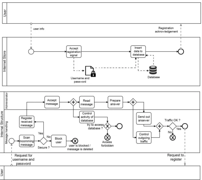
Figure 1 : Risks modeling process
Figure 1 presents a BPMN model describing a database login process between a user and the system. The top diagram represents the model without consideration of risks which can occur in the system. The bottom diagram represents the same model, but with risk occurrence taken in account. We can observe that this second kind of model can be very complex. In our context, modeling a global solar
power plant with this method is too heavy for modelers and users, hence the need to relocate risk treatment outside of the model rises. Therefore, risk must be handled in a different way.
● A risk can impact a task. It is be able to block, slow down or shorten (depending on a degree) as described in Figure 2
Figure 2 : Risk impacts a task
● As illustrated in Figure 3, a risk can influence in chain (increase or decrease the impact) or generate another risk.
Figure 3 : Risk causality chain
The first objective of this contribution is about defining an extension to Papyrus for dealing with risk management, which is outsourced from the model. Papyrus, an Eclipse based project, allows developers to model a UML diagram, and thanks to UML-profile mechanism, enable a UML-based diagram modeling language such as SysML or BPMN.
Figure 4 presents the abstract structure of the proposed architecture. The process model editor and the Moka execution engine are combined into the Papyrus tool. They both are connected to our external risk management module and can communicate with him.
The goal of this architecture is to create an ad-hoc extension to Papyrus in order to consider risks, hazards, and simulation constraints. This sub system is able to generate risk related events as inputs for tasks described by process modeler in the main simulation. All risks and issues are described according to equations defined in the ad-hoc extension, outside of the main model within an Excel file. The initial model and the risk management extension are external one to the other to keep them easier to manipulate. The main simulation reacts depending on constraints and hazards referenced and generated by the risk management module (as described in Figure 4).
Figure 4 : Defining and using risks in Papyrus
Because of the described objective to relocate and factorize risk computation (management) out of the main model, interoperability is required between the workflow process simulation and external risk features. To address the interoperability, this work proposes to involve a co-simulation standard which provides communication mechanisms between several external modules. Another way to communicate with the Moka engine is to request web services API. Thanks to this proposition, any complex system compliant with FMI standard, or providing a web API can be coupled to the simulation tool.
Functional Mockup Interface (FMI) standard proposes two modes of operation. - "Simulation exchange" used in this proposition and - "model exchange" mode which is still under development in the Papyrus community. Using this standard as model exchange would imply to model process in an external FMU and load it in the simulation.
4.2 Risk treatment handling
(Guermazi et al., 2015) explain that the Moka engine executes a fUML model. A mechanism called "Visitors" is executed in Moka at each steps of the simulation process. Visitors can be surcharged; developers can implement java code at each steps and define a custom behavior for a specific UML profile. This is our entry point to the Moka engine. During simulation execution, each task in the model are executed by the engine, specific visitor is called and executed. At this step, the engine can test the tasks names and parameters of the UML profile (see “Reference” link between “Risk & Hazard management” and “Process Model” in Figure 4). At the execution of the simulation, this risk module must know the name of each task of the model for allowing interactions with it.
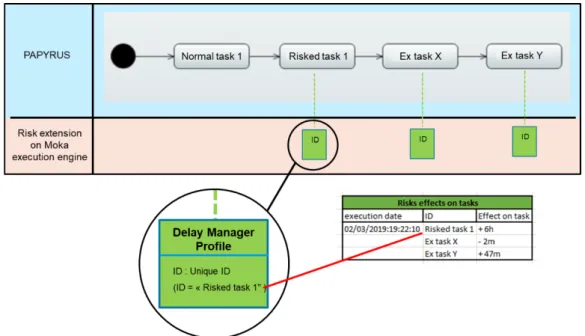
The entry point of the MOKA engine is a java function. From it, we can communicate with an Excel file containing risks equations defined by the company engineers. Each equation is linked to a task and determines the delay to apply on subject (described in Figure 5).
Figure 5 : Interaction between Moka extension and Excel file
The second step consists in adding a co-simulation environment with Java-FMI. This library allows developers to use an FMU for interacting with another external simulation. In our case, we are using OpenWeatherMap, a weather information web service. In our example, the location is given to the API and returns to the Moka visitor weather information. This information is relevant for a solar power plant: clouds or sunshine can impact the electricity production.
The Moka execution engine allows us to develop preconditions for tasks and resources. These conditions determine laws for tasks or resources in order to set them available, or not. With an FMU component coupled, a collaborative environment can control the elements execution (tasks or resources). For example, an element can only start under several additional conditions defined by other external tools.
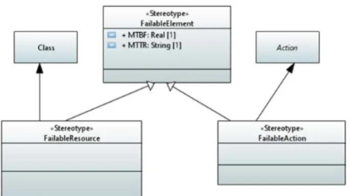
The implementation consists in creating a new extension of the UML metamodel (Figure 6). The users can add new concepts (classes) and relationships (associations) by using the profile and the stereotype mechanism. In our proposition, we created a specialized object “Failure Element” which can suspend the execution of an UML element (task or resource) based on the mean time between failure indicator and external variables (e.g. weather condition).
Figure 6 : UML Profile for loading Weather FMU
● stereotype “FailableAction”: applied on a UML actions with two attributes (by inheritance): (i) “MTBF”, Mean Time Between Failure, defines the average time during an action, can be executed before a failure occurs over a specified time. (ii) “MTTR”, Mean Time To Repair, is the average time required to repair a failed action (during this time the task ca not be executed).
● stereotype “FailableResource”: applied on a UML Class with the two same attributes by inheritance. Algorithme of failableResource is close to FailableAction’s stereotype. The only difference remains on thestereotype applied on a UML Class.
After defining the new UML profile, the second step consists in generating source code of this profile by using the Eclipse Modeling Framework (EMF). This code generator provides interfaces and a factory to create java object (see Figure 7).
Figure 7 : Code generated using EMF
The final step consists in associating the new Advices to the execution visitors, interacting with a FailureManager class. This can be done by customizing the execution engine and adding this implementation on a new Papyrus version. The FailureManager counts the number of FailableElement executions and can activate failures during the simulation. We also add the implementation of the two advices (FailureResource and FailureAction). The first one is associated to UML Class (Figure 6) which uses Resources with FailableResource stereotype. This advice asks to the failure manager if a task can start or finish, and it also executes additional start/finish actions for a given task. Concerning the second advice, it runs on/uses the same algorithm than
FailableResource. It checks with failure manager if a task can start or finish and executes additional start/finish actions for a given task. In the FailureManager, java code allows us to import and execute an FMU. This allows us to relocate complex calculations.
4.3 Time execution manager
In this context, dealing with complexity is about allowing a Papyrus instance to be synchronized with another one. To do so, technologies used in the previous chapter will be employed.
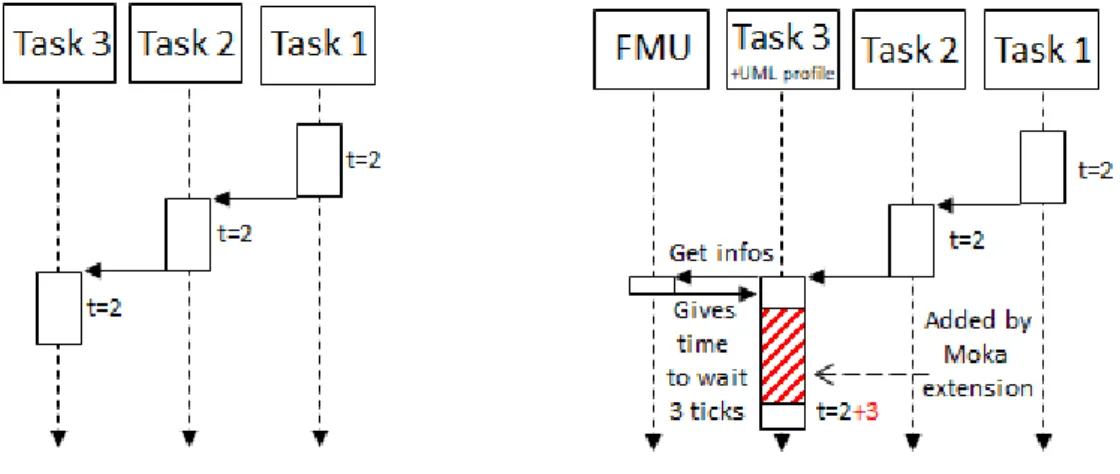
Figure 8 : Papyrus + Moka extension connected to Time Management FMU
Figure 8 represents a Papyrus instance with a simple BPMN model with custom UML profile, and a Moka extension connected to a federate. The Moka extension has access to the content of our current custom UML profile, as well as the whole simulation. In this extension, we are able to define (with java code) specific behaviors according to what is given by the UML profile. Figure 9 describes a simple example of how the UML profile and the Moka extension can affect a simple model. The left sequence flow diagram shows a normal process execution, without applying our Moka extension: each task is executed according to its “normal” time (normal time is the time affected to a task in fUML Papyrus model). In the right side of the figure, we applied our UML profile on Task 3 (as in Figure 8). We can see when Task 3 is executed, the Moka extension sends all the information contained in the UML profile to the federate. The FMU determines (based on the information contained in the UML profile) if this task should be delayed or not, and if yes, for how long. We can see on the right sequence flow diagram that the Moka extension extends the simulation time of Task 3 to 3 units of time.
In this example, the federate determines the delay time according to the content of the UML profile (name of the task, simulation time, etc) and uses databases, web services, and statistics algorithm to determine the delay.
(Bouanan et al., 2018) presents a hybrid HLA/FMU connected to an RTI, which communicates with an external application through the FMI standard. In our paper, we use the same approach: a hybrid HLA/FMU component able to communicate with one local Papyrus execution and a HLA federation.
4.4 HLA - Papyrus Bridge
The objective here is to run several Papyrus instances, each one having its own hybrid HLA component. We use the HLA standard for its functionality of time management, and communication protocols. The main objective is implementing waiting points between Papyrus instances. Using a HLA component enable also connection of other simulations to the final DS.
When an instance of Papyrus has to wait for another instance of Papyrus, messages are exchanged amongst them through the HLA communication mechanism. At the beginning of the federation, each federate subscribes to an interaction class “Message” (described in Figure 11) in order to be informed of every modification state during the global distributed simulation. The HLA mechanism does not allow a federate to address a message directly to a recipient. The federates can only publish and subscribe Objects or Interactions. During the simulation, each federate receives all interactions. They use “src” and “dst” attributes to identify if there are concerned by the message or not. If not, they simply ignore the message. If yes, they can publish an answer. When an instance of Papyrus enters in a synchronized state, the associated federate publishes an interaction in order to inform the other members.
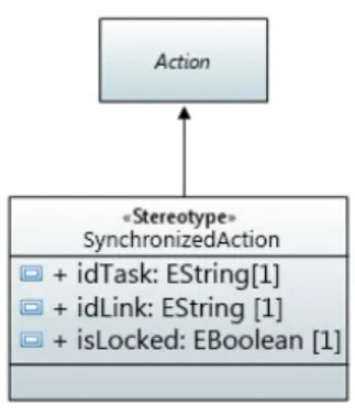
Each Papyrus instance has the same UML Profile and the Moka extension corresponding to the Figure 10 below.
Figure 10 : Custom UML Profile
Every synchronized Task (Action in UML syntax) inherits from “SynchronizedAction” Stereotype which contains:
● idTask: a unique identifier. It allows any federate to identify where it comes from. For example, P1.3 is the id of the Task 3 in the federate 1.
● idLink: id of the associated locker/unlocker task.
● isLocked: a Boolean variable which determines if it is a locking task or an unlocking task. At the execution of a synchronized task, the Moka extension shares with the HLA federate information contained in the profile. The federate behaviors depend on the status of the system.
Figure 11 : HLA FOM file
Figure 11 above corresponds to the content of the Federate Object Model (FOM) file. It describes every interaction which can occur between federates.
● src contains the unique id of the message transmitter. If it is a “lock” or “unlock” message, it contains ID of the linked task. If it is a reply to a lock message, it only contains its Papyrus id: “P1”.
● dst contains the target id of the message. With the HLA subscription and publication mechanism, it is impossible to address a message to a specific person. So, the federate is able to filter which messages are for them and which are not (if not, ignore them).
● localTime is given by the Moka extension. When a lock message is received, the recipient must reply by its own local time.
● isLocked is about the semantic of the message. 0 corresponds to an unlocking message. 1 corresponds to a locking message. 2 corresponds to a locking reply (the federate has to give its Papyrus local time).
During the simulation, each federate has the opportunity to send:
● a “lock message” when Papyrus enters into a synchronized point which needs an unlocking from another Papyrus process.
● an “unlock message” when Papyrus enters into a synchronized point which unlocks another Papyrus process.
● a “time reply message” when a federate receives a notification from a locked Papyrus process, it has to reply its actual local time.
From a technical point of view, we are using in this application the HLA Run Time Infrastructure (RTI) Pitch, a free version of RTI HLA 1516e compliant. The HLA federation works as a time regulating and time constraining federate. On the Papyrus instance side, the time is managed by the DEScheduler of the Moka engine.
At each nanosecond of the simulation, a function is called by the time scheduler to check if nothing commits in the event buffer. We added a function which check modifications in the federate outputs. If any modification is noticed, a new event is triggered in order to treat this event. If the Papyrus simulation has to send a message, the Moka extension asks to DEScheduler the local time and get in return the simulation time in nanoseconds after a conversion to milliseconds. This time is given to the federate.
4.5 Time management between Papyrus instances
The time synchronization between Papyrus instances is an important point. When an instance of Papyrus is locked by another one, its local clock must continue to fly. This waiting time must be simulated by the Moka extension. The federate interactions goal is to calculate this duration. Figure 12 illustrates a simple example of this time synchronization mechanism.
Figure 12 : Simple example of two Papyrus in BPMN
Here are two Papyrus instances which are interconnected by a synchronization point. They both have their own local time, and are completely autonomous until they reach the synchronization point (locked Task 3 and Unlock Task 6 of both process). Moreover, Papyrus instances 1 and 2 do not start at the same time, this delta t is visible on Figure 13. We can see that Papyrus instance 1 (P1) needs to wait for a message from P2 in order to achieved its local process. The synchronization point did not have a duration, in synchronized task P1.3, P1 must wait for an unknown number of ticks, so Moka cannot anticipate how much time this lock costs to P1. Hence, we need to calculate this duration and give it to Moka in order to observe the waiting time in the P1 simulation.
Figure 13 explains the main exchanges between the components of the simulation. In our example, each Papyrus instance has two normal tasks (e.g. P1.1, P1.2 & P2.4, P2.5), and two synchronized tasks (P1.3 & P2.6). Those two last tasks extend a custom UML profile.
Figure 13 : Sequence flow diagram of two Papyrus with synchronized points
At the beginning of the sequence flow diagram, each Papyrus instance has its own local time and starts its local process. To make it more realistic, each Papyrus instance starts at a different time. Δt represents the time gap between two Papyrus instances launches. It impacts time synchronization in order to illustrate time management mechanism proposed in this contribution. When P1 is locked (at t=2), Papyrus 1 federate (F1) publishes this information to all other federates. Then, the federate which will unlock P1 in the future must send back its own local time. Here, when P1 is locked, P2 is at t=1. P1 is now waiting to be unlocked and its local time is frozen.
P2 process execution continues until it has to unlock P1.6. The federate publishes this information with its own local time t=10. Federate 1 receives this information and knows which federate unlocked it. It can now determinate the duration of the lock: duration of P1.3 synchronized task = Tend - Tbegin = 10 - 1 = 9 ticks. Now, the Moka extension can unlock its local time and create a waiting time with a duration of 9 ticks. This process allows the use HLA mechanism in order to synchronize the local time of the different Papyrus instances.
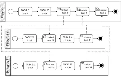
A more complex example was setup in order to test synchronization mechanisms. As a result, Figure 14 is a BPMN diagram describing this simulation scenario. P1 starts and unlocks P2 & P3. Secondly, P1 must wait for P2 and P3 to finish their own simulation. Another interesting point is that P3 releases P1 after P2, even if P1 must first wait for P2. In that case, P1 stays naturally locked and wait for P2 message. Then, P1.5 is immediately unlocked (more explanation later in the paper with Figure 15).
Figure 14 : BPMN process of 3 interconnected Papyrus
Figure 15 describes the technical architecture of our example. As introduced in Figure 14, there are three Papyrus instances working together. Each one of them has its own Hybrid HLA/FMI federate allowing communication between them through HLA Run Time Infrastructure.
Figure 15: Architecture of Papyrus Distributed Simulation
Figure 15 illustrates a second sequence flow diagram extracted from our example. To simplify graphical rendering, we decided to merge all local tasks and each instance of Papyrus in one single line: “Local tasks”. We also merged the synchronized task with the hybrid federate line (excepted for Papyrus instance 1), and hide the RTI component.
Figure 15 : Sequence flow diagram
According to Figure 15, we can track the execution steps of the Figure 14 model. This example allows to test the algorithm delay with a specific case study. P1 must firstly be unlocked by P2.24 and secondly by P3.34. When P1 enters in P1.3 lock, it asks to P2 about its current local time: starting time = 2 and stores this information for later.
P3 process is faster than P2. As a result, Figure 14 diagram shows that P3 send a release message at t=7, but P1 is not yet locked by P3. So, Federate 1 saves this message and does not impact P1 simulation.
Later, at t=10, P2 releases P1.4 lock. At this time, the federate first unlocks P3.34 and determines its delay: d = release time (10) - starting time (2). The Moka engine of Papyrus instance 1 can unlock its local time and set delay time to 8.
Then subsequently, the execution process goes in a second synchronized task P1.5, but it is immediately released: d = release time (7) - starting time (12) < 0 so no delay. Then, the distributed simulation ends since each Papyrus instance has reached its final task.
5. CASE STUDY
This paper was developed in an industrial context. This company which designs solar power plants has specific needs: this project consists in installing solar (panels fields) to provide electricity (between 5 and 100 megaWatt per hour, depending on the field size), heat (steam), drinkable water, and ice in a large area which is not powered so far. However, transport of solar panels fields is extremely expensive. To reduce the costs, the company is designing a mobile factory able to manufacture and assemble solar panels directly on production site. Transporting finished products are very bulky, only raw materials would be brought on construction spot. The main challenges of this project are : risks management in process conception and project management (Rodney, 2014),
factory miniaturization to fit in the least transport containers possible (Benama, 2014), and designing strongest structure at the lowest cost depending on the environment of the power plant (El Amine, 2016; Gorecki et al., n.d.; Piegay, 2015).
The complexity of this project leads the company to develop and use a custom M&S tool able to satisfy its needs: Papyrus. In this section, we will solve an issue with our paper propositions. Several models were created for several objectives. In our example, we use a high-level abstraction model about the power plant deployment. For this example, the model has the advantage of being clear, simple, it can reuse each proposition made in this paper, and technical values can easily be modified for intellectual property needs.
Modeling a power plant deployment can have several objectives. It can be done from an engineering point of view for studying and anticipate each technical issue. It can be done from a financial point of view in order to estimate costs of deployment. Or, in our example, from a seller point of view. Otherwise, in this example the goal is to determinate the end date of power plant deployment, depending on associated risks.
This context offers us the best conditions to validate our proposition. The proposition presented in the previous chapters as example were used in our company to solve their own issues, applied on their own models. Figure 16 represents a solar power plant deployment process from the higher abstraction level drawn on Papyrus. We use this model as example to illustrate the propositions, in particular the 4 bottom tasks surrounded by a rectangle.
Figure 16 : Main industrial model
The beginning of the process is represented by the black dot in top left of Figure 16. The first step “container carrying” consists on transporting and delivering containers on production site. Then, several processes can be simultaneously launched. “Mobile factory carrying”, “civil engineering”,
and “Row materials” steps are executed independently. The civil engineering part is required at several steps, so they are divided in 3 sub-parts “GC1”, “GC2” and “GC3”. Once the mobile factory is carried, the company has to deploy it and start it in the “Mobile Factory deployment + starting” step followed by the testing phase “Test Mobile Factory production”. Solar panels can be now deployed according the “GC1” in “Setup Solar Panels”. Finally, the company can finish installation of the power plant according to delivery of raw materials and tools in the “Team installation” step. “Commissioning” and “Delivery” are the final steps of the process.
As mentioned in the previous chapter, a Papyrus extension is associated to a custom UML profile applied on every task of the model in Figure 16. This profile (Figure 17) implements a fUML specification by defining a task duration (bringing capacity to execute the model over the time), and a Boolean “isLogged” allows task traceability.
With the implementation of a second UML profile for dealing with risks and hazards, the company is able to outsource time management out of the model.The user can apply a risk management profile on any task, and define to this task a unique ID (See Figure 17)
This UML profile implies a dedicated and a customizable Moka extension. During the execution phase, the extension is able to read a spreadsheet containing data about risks and hazards. The Moka engine can influence the current task duration according to information stored in the sheet. In our case, risks and hazards information are stored in an Excel sheet. Outsourcing risks management to Excel allows the user to reuse already existing models, databases, enjoy the power of Excel equations and VBA language.
Figure 17 : Risk management UML profile
In Figure 17, the user applies the risk & hazard profile DbActionFailure on “Mobile Factory deployment + starting” task. At the execution, the Moka extension refers to an Excel file which contains all mentioned ID in the main model. In the figure’s example, the Mobile Factory deployment + starting” task is delayed of 20 days. This result can be checked on Figure 21.
As we can see, the definition of this impact on simulation time is done in a spreadsheet, outside the model. However, this impact can be defined according to the current simulation result. At the execution of our task, Moka writes in the sheet the task’s execution date (see Figure 17).The user is therefore able to use this date in his own risk equation.
In our example, the definition of Mobile Factory deployment + starting length depends on several parameters / information:
● A seed generated for random parameters in equations ● Simulation date
● Location of the power plant
● Weather information (depending on location and date), with requesting a web service API ● Information about human resources
Those equations can be very complex or very simple. It only depends on what the user needs to describe. In our case, there were defined by the company.
The complexity management module deals with synchronization between Papyrus instances. As explained earlier, it allows the relocation models complexity in other Papyrus instances. This module also offers several advantages like intellectual protection of models or remote execution through a/thenetwork. This is done thanks to a second UML profile (Figure 18). In our case study, the synchronization point is needed at “Mobile Factory Carrying” step. This step is a locking task and will wait for an unlock message from another Papyrus instance. We can see on Figure 18 two Papyrus instances connected by a synchronization point.
Figure 18 : Complexity management UML profile
Papyrus 1 (Figure 18 left side) contains a locked task. At the execution of «Mobile Factory Carrying”, the simulation engine executes a Moka extension and freeze the Papyrus 1 simulation time. A time-request is then sent to Papyrus 2 (Figure 18 right side, as described in section 4.5). Simultaneously, Papyrus 2 is executed with its own local time. At the execution of «Checking components integrity”, a message is sent to Papyrus 1 in order to determine the freeze duration and unlock the Papyrus 1 simulation time.
Figure 19 : simulation sequence flow diagram
Finally, the decision-making extension is associated to a custom UML profile applied on every task of the model. This profile (Figure 20) implements fUML specifications by defining to the task a duration, and a Boolean “isLogged” allowing the task’s traceabilit. If parameter is true, the dedicated Moka extension would watch this task and print the logs in influx database.
Figure 20 : Decision making UML profile
After the simulation execution, the user can observe the Tasks logs through Graphana UI (Figure 21). This dashboard is fully customizable, it can access to all data which are present in InfluxDB, added by the UML profile in Figure 20.
Figure 21 : Graphana simulation result
Figure 21 shows the simulation result of the “Mobile factory deployment + starting” and “Mobile Factory Carrying” models presented earlier. Based on the risks’ extension and co-simulation extension, their delay is defined at the execution time by an Excel sheet containing scenario parameters. After simulation execution, we can observe main simulation results: time consumed to deploy the solar power plant. In our context, several scenarios were implemented by the company. Optimistic, Pessimistic, and several other possible scenario (depending on production site location, date of delivery, subcontractor engaged, etc.).
OPTIMISTIC PESSIMISTIC
Mobile Factory Carrying 30 days 45 days
Mobile Factory deployment 20 days 37 days
Test Mobile Factory 10 days 15 days
… … …
Figure 22 : Optimistic and Pessimistic simulation results
Figure 22 above, contain results of Optimistic and Pessimistic simulation result defined by the company. The first column contains KPI labels, column 2 and 3 are for optimistic and pessimistic results. This table is a summary of many KPI defined. Here, we only got 4 mains of them. We can see that there is a difference of 75 days between the two-opposite scenario. From these results, the company can create custom scenario in order to be optimistic in some tasks, and pessimistic in others.
6. DISCUSSION
In this paper, we have proposed a set of extensions to Papyrus for dealing with risk management, hazard generation and other complexity issues coming from our industrial context. This complexity has been separated into two objectives. The first one was consisting in distributed simulation, while the second one was focusing in outsourcing risk management. HLA mechanism implemented between Papyrus instances allow user to divide complexity of a model in several sub models. All these models can be relocated on several computers thanks to HLA standard. The second point is the outsourcing risk management aspect. As described in previous sections, we are able to separate main simulation model and risk simulation.
Figure 23: Discussion Papyrus proposition
As we can see on le left side of Figure 23, each Papyrus instances can load a model to represent a perfect system (or sub-system), without risk or hazard generation. This model will be reused in other future simulations. In a second point, several risk/hazard scenarios can be defined (right side of Figure 23) and applied to a model. They role will be to modify / deteriorate the perfect model loaded earlier. With this proposition, we are now able to build one single model, and to apply to it many risks management scenario defined by user.
7. CONCLUSION AND PERSPECTIVES
The main propose of this paper is divided in two objectives. We have in the one hand proposed an outsourcing risk management from the main model in order to obtain a more modular approach to ease the composition of complex models. Those propositions were made in the aim of helping users,
non-specialist of modeling and simulation, to identify and manage domain models. Those features are integrated into a decision-making tool with domain specific GUI in order to easily set and monitor M&S parameters.
On the other hand, the Papyrus community made the choice to open the software to Model Exchange (ME) of FMI standard. FMI ME permit the interoperability of Papyrus models with other simulation components of different kind. Nevertheless, this subpart of the standard does not include time and execution management. Therefore, we proposed in this paper to extend co-simulation mechanism of FMI with the time management mechanism of HLA. The end of this contribution implemented a first running distributed simulation version of Papyrus tool, being concretely used by our industrial partner.
Future works consist in the implementation of experimental framework for replicability of simulations. Introduction of hazard can be useful with the capacity of doing thousands of simulations in the same time and compare them together. Definition of more complex shared resources is also one of our future jobs. Indeed, actually, only time trigger can be exchanged between Papyrus simulations. Another goal would be to exchange resources and tasks between several Papyrus instances.
8. REFERENCES
Altuhhova, O., Matulevicius, R., Ahmed, N., 2013. An Extension of BPMN for Security risk management. International Journal of Information System Modeling and Desigh pp 93-113.
Barki, H., Rivard, S., Talbot, J., 1993. Toward an assessment of software development risk. Journal of Management Information Systems 203–225.
Benama, Y., 2014. Supporting make or buy decision for reconfigurable manufacturing system, in multi-site context. Ajaccio, France 150–158.
Better, M., Glover, F., Kochenberger, G., Wang, H., 2008. Simulation optimization Applications in risk management. International Journal of Information Technology & Decision Making, vol. 7, No. 4 571–587.
Bouanan, Y., Gorecki, S., Ribault, J., Zacharewicz, G., Perry, N., 2018. Including in HLA Federation Functional Mockup Units for Supporting Interoperability and reusability in Distributed Simulation. Proceedings of the 50th Computer Simulation Conference 1–12.
Dubois, E., Heumans, P., Mayer, N., Matulevicius, R., 2010. A Systematic Approach to Define the Domain of Information System Security Risk Management, edit dubois, Patrick Heymans. Intentional Perspectives on Information Systems Engineering 289–306.
El Amine, M., 2016. Integration of concept maturity in decision-making for engineering design: An application to a solar collector development. Springer-Verlag, London 235–250.
Ellner, R., Al-Hilank, S., Drexler, H., Jung, M., Kips, D., Philippsen, M., 2011. A FUML-Based Distributed Execution Machine for Enacting Software Process Models. ECMFA : Modeling Foundations and Application 2011 pp 19-34.
Franke, R., Mattsson, S.E., Otter, M., Wernersson, K., Olsson, H., Ochel, L., Blochwitz, T., 2017. Discrete-time models for control applications with FMI. Presented at the The 12th International Modelica Conference, Prague, Czech Republic, May 15-17, 2017, pp. 507–515. https://doi.org/10.3384/ecp17132507
Gorecki, S., Bouanan, Y., Ribault, J., Zacharewicz, G., Perry, N., 2018. Including Co-Simulation in modeling and Co-Simulation tool for supporting risk management in industrial context. International multidisciplinary modeling & simulation multiconference. (not yes published)
Gorecki, S., Zacharewicz, G., Perry, N., n.d. Using High Level Architecture in the SEE Project for Industrial Context. Proceedings of SOHOMA 2017 762, 281–290.
Guermazi, S., Tatibouet, J., Cuccuru, A., Dhouib, S., Gérard, S., 2015. Executable Modeling with fUML and Alf in Papyrus: Tooling and Experiments. EXE MoDELS 3–8.
IEEE Computer Society, 2010a. 1516.2-2010 - IEEE Standard for Modeling and Simulation (M&S) High Level Architecture (HLA)-- Object Model Template (OMT) Specification. (https://standards.ieee.org/standard/1516_2-2010.html)
IEEE Computer Society, 2010b. 1516-2010 - IEEE Standard for Modeling and Simulation
(M&S) High Level Architecture (HLA)-- Framework and Rules.
(https://ieeexplore.ieee.org/document/5553440)
IEEE Computer Society, 2003. IEEE Recommended Practice for Distributed Simulation Engineering and Execution Process. (https://standards.ieee.org/standard/1730-2010.html)
Marcinkowski, B., Kuciapski, M., 2012. A Business Process Modeling Notation Extension for Risk Handling. International Conference on Computer Information Systems and Industrial Management 374–381.
Paté-Cornell, E., 2002. Risk and uncertainty analysis in government safety decisions. Risk Analysis 633–646.
Piegay, N., 2015. Optimisation et aide à la décision multi-objectifs pour la conception robuste de structures métalliques sur fondations superficielles isolées. Geotechnical Safety and Risk, Rotterdam, the Neterlands pp 419-424.
Rodney, E., 2014. Integrating Risks in Project Management. 16th International dependency and structure modelling, Paris 419–424.
Yilmaz, F., Durak, U., Taylan, K., Oguztuzun, H., 2014. Adapting Functional Mockup Units for HLA-compliant Distributed Simulation. 10th International Modelica Conference 247–257.