Science Arts & Métiers (SAM)
is an open access repository that collects the work of Arts et Métiers Institute of
Technology researchers and makes it freely available over the web where possible.
This is an author-deposited version published in: https://sam.ensam.eu Handle ID: .http://hdl.handle.net/10985/8821
To cite this version :
Jing JIN, Jean-Frederic CHARPENTIER, Tianhao TANG - Preliminary Design of A Torus Type Axial Flux Generator for Direct-Driven Tidal Current Turbine - In: Green Energy, 2014
International Conference on, Tunisia, 2014-03-25 - Green Energy, 2014 International Conference on - 2014
Any correspondence concerning this service should be sent to the repository Administrator : archiveouverte@ensam.eu
Preliminary Design of A Torus Type Axial Flux
Generator for Direct-Driven Tidal Current Turbine
Jing JIN
Shanghai Maritime University Shanghai, China jinjing0429@hotmail.com
J.F.Charpentier
French Naval Academy (IRENav) Brest, France
jean-frederic.charpentier@ecole-navale.fr
Tianhao TANG
Shanghai Maritime UniversityShanghai, China tianhaotang.c@gmail.com
Abstract—This paper focuses on the preliminary design of a
TORUS type AFPM generators used in the MW graded tidal current application. Two different structures can be derived based on the orientation of the main flux. In this paper, an analytical design model for this kind of machine is developed. This model is associated to a basic cost model to estimate the rough cost of the active materials of the machine. This two models are used in a common set of specification corresponding to high power tidal current turbine generator. This method allows a first comparison of these two structures for this application.
Keywords—renewable energy; tidal current energy; permanent magnetic synchronous machines; axial flux machine, TORUS.
I. INTRODUCTION
Confronting the issue of energy shortage and environment pollution, it is necessary to develop renewable energy instead of conventional fossil fuels (petroleum and coal) to minimize the impact of human activities on climate changing and solve the fossil energy deficiency problem. Among all the renewables, wind energy and hydropower are well developed. Recently marine energy has been a hotspot in researches. Marine energies can be related to swell, tide, tidal stream or thermal conversion (OTEC). In this paper the study is focused in the way to extract efficiently tidal stream energy.
Tidal stream energy is a regular, predictable and stable energy resource. According to the data, the potential exploitable resource is up to 50 GW or 180 TWh/year [9]. The extraction principle is shown in fig.1; tidal current turbines capture the kinetic energy caused by the tide related horizontal motion of sea water. A marine tidal current energy system converts this kinetic energy in electricity with a turbine a generator and a power drive which is classically connected to a power grid. So the general principle of the system is mainly similar to a wind power system. The general equation of the harnessed power is given by Equation (1).
3 1 1 2 in p tide P C
A v (1)where:A1 is the area of the cross section, and Cp is the power
factor ranging between 0.35 to 0.5 according to the characteristics of the turbine [1]. For the same power range and for typical tidal fluid speed, a tidal current turbine is more compact than a wind turbine, because the density of sea water ρ [kg/m3] is around 1000 times higher than that of the air.
M
tide
v
Fig.1 Extraction Principle of the Tidal Stream Turbine
With the increasing awareness of environmental protection and green energy, tidal stream energy will definitely occupy a part in the energy structure. In order to generate energy in the most economic way, reducing the cost of power production and improving the performance of the turbine, it is necessary to optimize the generator used in the tidal stream system.
The study deals with direct-driven permanent magnetic synchronous generators. This kind of generator can be a very interesting solution for tidal energy systems because they are characterized by a high level of torque density, efficiency and reliability (the gearbox is one of the main cause of downtime and failure in turbine systems).
Considering PMSM structures, there are also various configurations that can be used for direct-driven tidal stream turbines. According to the orientation of the flux direction, these solutions can be classified as: the radial flux (RF), the axial flux (AF) and the transverse flux (TF) machines.
Concerning the characteristics and practical requirements of the direct-driven tidal stream turbines, such as the low speed and high torque, the AF generators can be attractive, because this configuration can improve the torque density and be less difficult in manufacturing than TF machine. These structures allow obtaining a better torque density because it is possible to multiply the number of air gap in the system.
However, there still existed some drawbacks at that time, such as, for example, the strong axial magnet attraction force between the stator and the rotor which is leading to the difficulties in maintaining the uniform air gap. That is one of
the main reasons why the RF machine had become the standard in electrical machine and has been developed more than the AF one.
With the development of PM excitation and the availability of high magnetic energy products, the use of AF Permanent Magnet configurations (AFPM machine) has to be reconsidered. Recently, due to its specific aspect ratio, the AFPM machine has been developed in special applications, which are limited in the axial length. For such specifications, this kind of machine can be an alternative to the classical RF configuration.
This is the reason why the presented study focuses on AF generator modeling and design for tidal stream application.
II. DESCRIPTION FOR THE AXIAL-FLUX MACHINE The AFPM machine (as shown in fig.2) can be designed in many different configurations considering the position or the number of the stator(s) with respect to the rotor(s): single side or multistage structure, internal or external rotor(s) with surface mounted or buried PMs, slot or slotless stator(s). The simplest structure is the single-sided with one rotor and one stator, as shown in fig.2(a). Fig.2(b) and fig.2(c) are double-sided structures. The former one is with external rotors, which is also called “TORUS” [6]. On the basis of the magnet arrangement, north-to-north or north-to-south for the opposite position in the rotors, the main flux in the stator yoke can flow circumferentially or axially (see in fig.3). So it is possible to make two kinds of windings to produce the electromagnetic torque, the former type is applied to the toroidal windings and the N-S type is applied to the classical windings.
(a) (b) (c)
Fig.2 Basic configurations of the AFPM machine
N c S a c N a c S a F b F b a c S N N S F a c b a c a c b a c (a) N-N type (a) N-S type
Fig.3 Flux directions for both N-N type and N-S type magnet arrangement of 2R-1S AFPM machine
Axial structures with two stators/one rotor and one stator/one rotor has been already studied for tidal stream application in literature[8]. In this paper, we will focus on a two-rotors-and-one-stator (2R-1S) “TORUS” structure.
In the following parts, we will introduce a first order analytical model used to determine the EM performance of this structure as a function of the main dimensions of the machine. The model will lead to establish sizing equations. This method will be used to make preliminary design of TORUS machines for typical specification of a 1MW tidal stream turbine.
III. ANALYTICAL MODEL FOR THE AIXAL-FLUX MACHINE DESIGN
In this section, we will focus on the description of analytical model to determine the main dimensions of the 2R-1S studied machine. In an axial flux machine the dimensions and quantities change with radius. As a result, for example, the electric and the magnetic loads vary with the radius. Several hypotheses are done to establish this first order model:
Leakage effects are neglected.
The iron parts (core, teeth, etc.) are considered as infinitely permeable.
Only first harmonic is considered for flux density and EMF.
A 3-phase full pitch single-layer winding is used with 1 slot per pole and per phase.
The machine is considered to be associated with a back to back full IGBT converter which allows to control sinusoidal currents in the windings in phase with EMF (=0) in the rated operating point (design point).
A. Geometry and main dimensions of the AF generator Fig.4 depicts the 3D view and the geometric dimensions of the studied three-phase 2R-1S TORUS type AF machine, in which the slotted stator is located between the two rotors. For the sake of clarity, the mechanical parts like the shaft are omitted in the figure.
As shown in the figure, the rotors and stator have some same dimensions, like the outer and inner radii represented by Rout [m] and Rin [m] respectively. According to Equation (1),
the external radius of the turbine Rt [m] can be fixed in
accordance with the demand of input power. With a certain Rt,
the outer radius of the generator cannot be designed as large as you want to gain a high torque, because the nacelle volume will influence tidal flow in the turbine disk and will consequently decrease the energy conversion efficiency of the tidal stream turbine. Considering this phenomenon the maximum generator radius has been limited to:
1 3
out t
R R (2) The average radius Ravg [m] and the corresponding average
2 avg in out p R R R p p
(3) where: p is the number of pole pairs.In an AF machine, dimensions are changing with radius along the air gap. So we use the index notation to disambiguate the same parameters in different radius plane, i.e. ws,avg [m] and
wt,avg [m] are the corresponding slot width and the tooth width
on the average radius:
, , p s ws avg wt avg mq
(4) Where: m is the number of phase (here m=3) and q is the number of slot per pole and per phase (here q=1).R in R avg Rout r dr N N N S S N S S S S N N O O 1 O 2 wt,avg tooth slot ws,avg τp b) Rotor c) Stator
a) 3D view of the TORUS
Fig.4 Specific definitions for the main geometrical parameters for the AF B. Air-gap flux density
In order to take slot effect into account, the Carter’s coefficient kc is introduced to correct the physical air gap
thickness g [mm]. The thickness is chosen as 0.15% of the average diameter Davg [m] to take into account mechanical
tolerances. The relative air gap g’ and the Carter’s coefficient can be defined as:
s c s k r g
(5) 2 , , , 4 arctan ln 1 2 2 2s avg s avg s avg
w w w r g g g
(6) , d t avg s w
(7) βd is the teeth opening ratio. In order to prevent the teethsaturation, this value is chosen as:
g d sat B B
(8) Bsat represents the maximum magnetic flux density in theteeth iron or the stator yoke iron and Bg is the maximal value of
the magnet flux density in the air gap. To maintain the saturation level constant along the radius, we suppose here that the angular width of teeth and slot keeps constant, which means the teeth opening ratio βd remain unchanged while
radius varies.
Bg is determined by the characteristics of the chosen PM
and the thickness of the air gap.
1 r g rm M B B g h
(9)where: hM is the air gap thickness in meter. Br [T] and rm are
the magnet magnetization and relative magnetic permeability respectively.
Fig.5 illustrates the theoretical waveforms of flux density over a pole pitch on the average radius if flux leakages are neglected. So the relationship between the peak flat-topped value Bg [T] coming from the PMs and the first harmonic
magnitude of the air-gap flux density is given by the following equation: max 4 ˆ sin 2 M g B B
(10)Fig.5 Air gap flux density waveform over a pole pitch
For the N-N type, the air gap flux created by each PM will be divided into two when it passes the yoke to form two different closed circuits. And there is a symmetric structure in the inner stator. So the height of the stator yoke hy_s can be
determined as: _ 2 i avg g y s sat D B h pB
(11) It can be assumed that the height of the yoke in the rotor hy_r ishalf that of the stator. In the N-N type structure, the choice of the thickness value of stator yoke in N-S type is not related to the flux in the yoke. It has been chosen only to ensure the mechanic strength requirements. This feature implies a reduction in iron losses. However, the lap windings, instead of the toroidal ones, imply longer end windings, which results in an increasing in the copper losses.
C. Electric load A and current density Js
Electric load A [A/m] is an important parameter, because it is related to the thermal behavior of the stator and the cooling method to be used to limit the temperature in the active parts of the electric machine. Usually, for air cooled machines,
values of A in the 10 to 50 kA/m range are used. However, when A is between 80 and 150 kA/m, more complex cooling systems should be used.
In the presented study, the notation A represents the line current density on the inner stator radius Rin. This value will
serve as the criteria of the cooling method and is given as follows: 1 a in mN I A R
(12)where: N1 is the total number of conductors of one phase in
one face of the stator and Ia is the RMS value of the phase
current.
As shown in the fig.4, there are Ns conductors with Sc
[m2] effective copper cross area in each slot. Here, we introduce the slot fill factor kf to build the relationship between
the effective copper cross area (Ns·Sc) to the slot cross area
As: s c f s N S k A (13)
The armature winding RMS current density Js [A/m2] at
the average radius can be defined as:
1 2 a s f s mN I J k A Z (14)
where: Z is the total number of slots in the two faces of the stator.
So the height of the slot hs[m] can be determined as:
(1 ) in s s d f avg AR h J
k R (15) D. Electromagnetic Torque Tem [5]Fig.6(a) illustrates the production of the EMF over a continuous radius in the considered axial-flux machine. According to faraday electromagnetism induction law, the elementary EMF de caused by a conductor in a length of dr is:
( ) ( ) de
B
rdr (16) r z θ r dr O1 O2 equiouter equiinner (a) (b)Fig.6. (a) Production of the EMF and (b) geometric illustration for the winding coil applied in the N-S structure
Considering an AF machine structure with double air gaps, on the basis of above equation, the average electromagnetic torque developed by the machine can be derived as:
1 2 2 1 max ( ) ( ) 2 2 m phi phi em i w in out in e i P T k AB R R R
(17) E. Copper lossesA direct-driven synchronous generator associated with a marine turbine rotates with a slow speed. As a result, the electromagnetic torque of the machine is rather high, and the machine is needed to be relatively large. So the copper losses caused by end windings cannot be neglected.
Fig.6(b) illustrates the geometric consideration for the N-S type end windings. The total length of one conductor Lcu, the
equivalent length of half outer ends equiouter and half inner ends
equiinner for the winding encumbrance can be estimated as
follows[3][4]: _ , 4 sin , 2 2 y s outer out h for N N type equi R for N S type p
(18) tan( ) 2 2 2 inner in equi R p p
(19) outer innerLeqequi equi (20)
cu out in eq
L R R L (21) The resistivity of the copper depends on the working temperature. For the studied cases, during the normal work, the machine copper working temperature is assumed to be constant and equal to 115°C. The resistance of the armature winding for one phase is commonly expressed as
1 T cu cu c N L R S
(22)So the copper losses can be estimated as follows:
2
cu a cu
p mI R (23) F. Core losses[2]
The core losses including the hysteretic, eddy current and the additional losses, within a volume Vol under a sinusoidal
flux density with a peak value Bmax1, can be estimated as:
2 2
2max1
Fe ad F H ol
p k k p k pV B (24) where : kad,kF and kh are the specific loss coefficients for the
additional, eddy current and hysteretic respectively.
Neglecting the mechanical and stray losses, it is possible for us to calculate electromechanical efficiency, which can be expressed as: 1 1 out cu Fe in in in p P p p P P P
(25)G. Eestimation of the cost
It is necessary for us to estimate the material cost of the studied machine to compare the studied solution to other ones in an economical point of view. It is the reason why the total cost of the active materials used in the generator is roughly calculated. The unit-prices and mass densities of these active materials are listed in table I.
TABLE I. MASS DENSITY AND UNIT PRICE FOR ACTIVE MATERIALS Material Mass Density [kg/m3] Price Per Kilogram [€/kg]
Copper Winding 8.9×10³ 10
Laminated Iron 7.9×10³ 1
NdFeB Magnet 7.5×10³ 50
IV. RESULTS AND ANALYSIS
This section presents the preliminary design results and analysis. A common rated operating point is used as specification for the generator design. This specification set, which is summarized in the first lines of table II, corresponds to a 1MW tidal turbine with a diameter of 27.6m and a rated tidal current velocity of 2m/s. The main design criteria used in this paper is to maximize the efficiency for this rated point. From this specifications and a set of common fixed values which are given in Table II, it is possible using the model described in previous sections to estimate the main dimensions of the corresponding AFPM generator.
TABLE II. LIST OF CONSTANT PARAMETERS
Constant Parameters Value
Total input mechanical power Pin, [MW]: 1
Rated power coefficient of the turbine Cp: 0.4
Rated current velocity vtide, [m/s]: 2.0
Rated rotational speed of the shaft n1, [rpm]: 12
Phase number m: 3
Electric frequency felec: 60
Number of slots per pole per phase q: 1 Permanent magnet remanence Br, [T]: 1.2
Air gap flux density (flat-topped value) Bg, [T]: 0.7
Maximum magnetic flux density in the teeth or the yoke iron Bsat, [T]: 1.4
PMs polar pitch occupation βM: 0.67
Slot fill factor kf: 0.7
Winding factor kw1: 1
Constant Parameters Value
Current density Js, [A/mm2]: 5
Line current density A, [A/m]: 50000 Phase voltage Ea, [V]: 690
The model and assumptions presented in the previous parts have been implemented in Matlab environment. After calculation, the main dimension results for different TORUS structures are as follows:
TABLE III. LIST OF MAIN DIMENSION FOR TORUS
Output Data for Axial Flux Machine N-N type N-S type
Maximum efficiency η is: 94.5% 94.3% Inner stator radius Rin, [m]: 4.24 3.69
Outer stator radius Rout, [m]: 4.31 3.78
Slot width Ws,avg, [mm]: 7.5 6.5
Height of the slot hs, [mm]: 28 28
Thickness of the stator yoke hy_s, [mm]: 15 6.5
Thickness of the rotor yoke hy_r, [mm]: 7.5 6.5
Height of the PM per pole hM, [cm]: 2.0 1.7
Cost of the active materials, [Euro]: 23030 23811 In the fig.7, the blue line shows the relationship between the outer stator radius Rout and total efficiency for the N-N type
AF machine. It had been mentioned that the Rout value has to
be lower than Rmax, equaling to Rt/3, for hydrodynamic reasons.
The maximum value of efficiency appears at the point when Rout equals to 4.3 m, which is fortunately within the authorized
domain. It also can be concluded that the machine can be designed with a lower cost; however it will be at the cost of the efficiency. In the TORUS configurations, except for the PM and windings arrangement and the thickness of the stator, the physical structures for the two types are pretty the same. This is the reason why a similar analysis can be led for the N-S case.
2 2.5 3 3.5 4 4.5 5 5.5 6 6.5 7 0.88 0.89 0.9 0.91 0.92 0.93 0.94 0.95 0.96 Total efficiency Rout (m) Eff ic ie n c y Rmax:4.6 m Highest efficiency: 94.5% Lowest cost: 23011€
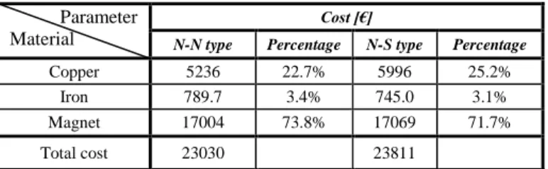
According to the design results, we estimate the rough cost for the both structures. The details are presented in Table IV.
TABLE IV. ESTIMATION OF THE COST FOR THE TORUS
Parameter Material
Cost [€]
N-N type Percentage N-S type Percentage
Copper 5236 22.7% 5996 25.2% Iron 789.7 3.4% 745.0 3.1% Magnet 17004 73.8% 17069 71.7% Total cost 23030
23811 Under the same conditions and design methods, the efficiency of radial flux machine seems to be lower, and the total cost is greater than that in the studied cases (AFPM). So the axial flux machine, with a less effective length, seems to be really attractive for the MW range tidal current turbine applications. However it is obvious that complementary studies have to be led to finally conclude in this point. In particular, 3D FE analysis has to be done to validate the EM design. Thermal behavior, mechanical behavior and association of power electronics has also to be studied to evaluate the impact of the chosen structure on the generator integration, the price and the efficiency of the global system.
V. CONCLUSION AND PROSPECT
In order to make the best use of the tidal stream energy and reduce the cost of generation, it is necessary for us not only to research the control methods of the system, but also to optimize the performance of the generator used in the tidal stream applications.
According to the preliminary presented study presented in this paper, TORUS AFPM generators can be attractive structures for the MW range tidal current turbine application. Complementary studies have to be led in the future to conclude on the interest of these AFPM generators for this kind of specifications.
ACKNOWLEDGEMENT
This work was supported by Shanghai international science and technology cooperation projects (1160707800) and Ph.D. programs foundation of Ministry of Education (20113121110002). The authors are grateful for the support.
REFERENCES
[1] S. E. Ben Elghali, M.E.H. Benbouzid and J.F. Charpentier, “Marine Tidal Current Electric Power Generation Technology: State of the Art and Current Status,” IEEE, pp. 1407–1412, 2007.
[2] N. Bernard, F. Martin, and M. E. Zaim, “Design Methodology of a Permanent Magnet Synchronous Machine for a Screwdriver Application,” IEEE Transactions on Energy Conversion, vol. 27, no. 3, pp. 624–633, September 2012.
[3] A. Chen, R. Nilssen and A. Nysveen, “Performance Comparisons Among Radial-Flux , Transverse-Flux PM Machines for Downhole Applications,” IEEE Transactions on Industry Applications, vol. 46, no. 2, pp. 779–789, March/April 2010.
[4] A. Cavagnino, M. Lazzari, F. Profumo and A.Tenconi, “A Comparison Between the Axial Flux and the Radial Flux Structure for PM Synchromous Motors,” IEEE, pp. 1611–1618, 2001.
[5] Jacek F. Gieras and Mitchell Wing, “Permanent Magnet Motor Technology Design and Applications Second Edition, Revised and Expanded,” Marcel Dekker, Inc., U.S.A, 2002.
[6] A. Parviainen, “Design of Axial-Flux Permanent-Magnet Low-Speed Machines And Performance Comparison Between Radial-Flux and Axial-Flux Machines,” Lappeenranta University of Technology, April 2005.
[7] Luc Moreau, “Modelisation, Conception Et Commande De Generatrices A Reluctance Variable Basse Vitesse”, Thèse de Doctorat de l’Université de Nantes,9 décembre 2005.
[8] S. Djebarri, J.F. Charpentier, F. Scuiller, M. Benbouzid and S. Guemard, “Rough Design of a Double-Stator Axial Flux Permanent Magnet Generator for a Rim-Driven Maritime Current Turbine,” Industrial Electronics (ISIE), pp. 1450–1455, 2012 IEEE International Symposium.
[9] Tim Cornelius and Mike Smith, PRESENTATION TO OFFSHORE ENGINEERING SOCIETY TIDAL STREAM ENERGY, 7th October