Science Arts & Métiers (SAM)
is an open access repository that collects the work of Arts et Métiers Institute of
Technology researchers and makes it freely available over the web where possible.
This is an author-deposited version published in: https://sam.ensam.eu Handle ID: .http://hdl.handle.net/10985/11614
To cite this version :
Tarek MARRAY, Philippe JACQUET, Mohammed MANSORI, Agnès FABRE, Laurent
BARRALLIER - A Thermodynamic and experimental study of low-alloy steels after carbonitriding in a lowpressure atmosphere Metal Science and Heat Treatment, Vol. 56, n°78, p.434439 -2014
Any correspondence concerning this service should be sent to the repository Administrator : archiveouverte@ensam.eu
A THERMODYNAMIC AND EXPERIMENTAL STUDY OF LOW-ALLOY
STEELS AFTER CARBONITRIDING IN A LOW-PRESSURE ATMOSPHERE
T. Marray,
1, 2P. Jacquet,
1, 3M. Mansori,
4A. Fabre,
2and L. Barrallier
2Translated from Metallovedenie i Termicheskaya Obrabotka Metallov, No. 8, pp. 34 – 39, August, 2014.
The effect of the composition of two steels (B and 6MnCr5) on precipitation of undesirable phases (carbides, nitrides and carbonitrides) under thermochemical treatment (low-pressure or vacuum carbonitriding) is inves-tigated. Metallographic and x-ray diffraction studies and thermodynamic computations are performed. Key words: carbonitriding in low-pressure atmospheres, vacuum carbonitriding, carbides, carbo-nitrides, alloy steel.
INTRODUCTION
In many practical cases the performance of a structural component depends on the mechanical properties of the sur-face [1]. Many methods of thermochemical treatment are used to raise the properties of the surface, such as gas rizing [2 – 4], carbonitriding [2, 4], and low-pressure carbu-rizing (vacuum carbucarbu-rizing) [5 – 7].
Conventional methods of thermochemical treatment of steel are based on diffusion of carbon and (or) nitrogen in surface layers. Carbonitriding, which is known to be more advantageous than standard carburizing, especially at a low thickness of the hardened layer, is commonly performed in conventional atmospheres [4, 8]. Published information on low-pressure carbonitriding (LPCN) is quite scarce [9, 10].
Due to the intrinsic nonequilibrium of the low-pressure treatment the conventional methods [11, 12] are inapplicable for controlling such processes. For this reason, we used com-puter simulation to predict the relation between the effective thickness of the hardened layer and the accurate profiles of the distribution of carbon and nitrogen in steels [13 – 18].
On the whole, the process of carbonitriding (developed on the basis of carburizing) is performed in two stages. The first stage, which is usually termed a boost one, provides de-livery of a high content of carbon and nitrogen from the at-mosphere to the surface. The second stage, i.e., diffusion,
consists in keeping the parts at a constant temperature in va-cuum (after cutting off the gas flow to the atmosphere).
Such division of the process of LPCN makes it possible to avoid transition through the maximum solubility of carbon in the austenite and hence to prevent precipitation of undesir-able phases such as M23C and M7C3carbides and M(C, N)
carbonitrides. Earlier studies of alloys of the Fe – Cr – C sys-tem treated in a conventional manner have revealed forma-tion of microstructures represented by a-ferrite and M3C, M7C3and M23C6complex carbides depending on the alloy-ing of the metal [19, 20].
The aim of the present work was an experimental and computational study of the effect of the composition of steels on undesirable precipitation in the process of low-pressure carbonitriding.
METHODS OF STUDY Studied Steels
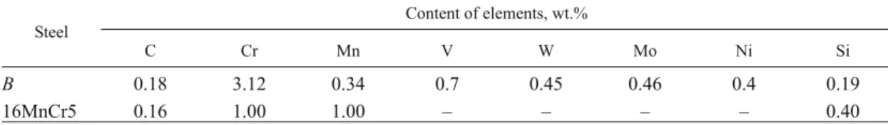
The samples for carbonitriding were fabricated from two low-alloy steels the chemical compositions of which are given in Table 1. The low content of carbon in the steels guarantees a tough core in the parts after carbonitriding.
All the samples had a cylindrical shape and were Æ16 ´ 20 mm in size. Both end faces were ground before the treatment.
Low-Pressure Carbonitriding
Most of the results presented were obtained using a com-mercial BMI Fours Industriels furnace that had earlier been
1 Laboratoire de Science des Matériaux, ECAM, Lyon, France. 2 Arts et Métiers ParisTech, MSMP, Aix en Provence, France. 3 Arts et Métiers ParisTech, LaBoMaP, Cluny, France.
4 Laboratoire de Chimie des Matériaux et Evironnement,
used for developing a sensor for monitoring processes of low-pressure carburizing [6]. The samples were subjected to LPCN at 860°C in a BMIBMicro vacuum furnace. Carbon-and nitrogen-bearing atmospheres were created by feeding ethylene and ammonia in the stages of carburizing and carbonitriding, respectively (Fig. 1). The pressure, the gas flow, and the duration of such treatments were optimized in order to provide a saturated layer with a thickness of 0.9 mm on the basis of results of the experiments described in detail in [18, 21]. The thickness of the saturated layer was deter-mined from the data obtained by measuring the hardness; the hardness of the layer should exceed 550 HV after quenching. The concentration profiles of carbon and nitrogen were measured with the help of a LECO analyzer and by the method of glow discharge optical emission spectroscopy, re-spectively. The metallographic analysis of the carbonitrided layers was performed after etching the metallographic speci-mens in Nital and Murakami reagents. The hardness profiles were obtained using a Buehler Micromet 2100 device at a load of 1 N. The maps of distribution of the chemical ele-ments in the carbonitrided samples were obtained with the help of scanning electron microscopy and x-ray diffraction analysis. To determine the phase composition the x-ray dif-fraction spectra were obtained in cobalt Ka radiation with wavelength 0.1789 nm.
RESULTS AND DISCUSSION Experimental Studies
Figure 2 presents the microstructure of the studied steels after LPCN (with duration exceeding that in Fig. 1) and oil quenching. The structure of steel B is represented first by martensite and then by bainite in the direction from the sur-face to the core (Fig. 2a ). The sursur-face zone of steel 16MnCr5 (with a thickness of 200mm) contains retained austenite. Martensite and bainite are detectable at a distance h = 200 – 500mm from the surface. The core of the sample contains perlite and ferrite (Fig. 2b ).
The curves of hardness distribution presented in Fig. 3 match the observed structures. In steel B the hardness is approximately constant (800 HV0.1) at h = 0 – 400mm and then decreases gradually. In steel 16MnCr5 the hardness de-creases in a layer with a thickness of 200mm, which corre-sponds to the presence of a “dark component.” A maximum hardness (750 – 800 HV0.1) is attained at h = 200 – 400mm. Then the hardness decreases upon the appearance of equilib-rium components (ferrite and perlite) in the layer at h = 400 – 700mm.
To determine the presence or absence of chromium-bear-ing carbides we used the Murakami reagent. Such precipita-tion has not been detected in carbonitrided steel 16MnCr5. This cannot be said about steel B, a typical microstructure of which is presented in Fig. 4. The surface layer of the steel ex-hibits four zones that correspond to the detected distribution of carbides over the thickness of the sample. From the sur-face to h = 90mm the fraction of the chromium-bearing car-bides is 1.65%. At a distance h = 90 – 200mm the proportion of these carbides attains a maximum (6.4%) and then de-TABLE 1. Nominal Chemical Compositions of the Steels of Grades B and 16MnCr5
Steel Content of elements, wt.% C Cr Mn V W Mo Ni Si B 0.18 3.12 0.34 0.7 0.45 0.46 0.4 0.19 16MnCr5 0.16 1.00 1.00 – – – – 0.40 Pressure 25 mbar Òåmperature 860°Ñ 5 bar 1 bar Dif fu sion CH24 NH 3 N2 t, min 33 12 45
Fig. 1. Scheme of a cycle of low-pressure carbonitriding (LPCN).
50 mm
50 mm
Fig. 2. Microstructure of steels B (a) and 16MnCr5 (b ). Etching with Nital (light microscopy).
creases gradually to 1.3% (h = 200 – 310mm) and 0.4% (h = 310 – 400mm).
To understand this trend, the profiles of carbon and nitro-gen concentrations were imposed on the micrographs ob-tained after etching steel B in the Murakami reagent (Fig. 4).
A carbon content exceeding 1 wt.% was observed in a sur-face layer up to 310mm thick. A nitrogen content exceeding 0.6 wt.% was preserved in the next layer with a thickness of up to 20mm and decreased progressively to 0.2 and 0.07% in the layers 100 and 200mm thick, respectively.
The imposition of the profiles of C and N concentrations on the micrographs reflects the probable effect of nitrogen on the formation of chromium-bearing carbides. Indeed, only the nitrogen concentration varies between the surface and h = 310mm. When the nitrogen content exceeds 0.2%, etch-ing with the Murakami reagent reveals chromium-bearetch-ing carbides in an amount of 1.65%. This concentration in-creases by a factor of 4 (to 6.4%) when the nitrogen content falls below 0.2%.
Finally, when nitrogen is not detected in the surface layer, the fraction of the precipitates containing chromium is the lowest (< 1%).
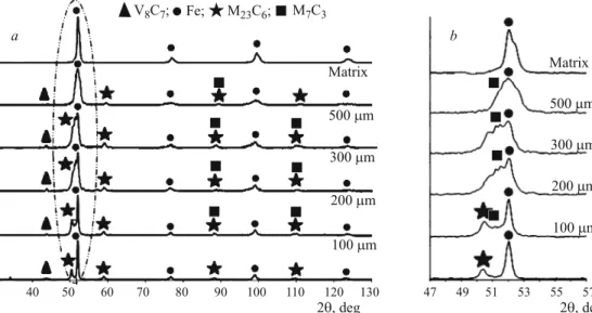
To obtain diffractograms at different distances from the surface (surface; h = 100, 200, 300, 500mm; core) we re-moved layers with a specified thickness from carbonitrided samples. It can be seen from Fig. 5 that the diffractograms re-flect the presence of M23C6and V8C7carbides on the surface in addition to thea-phase. At a certain distance from the sur-face there appear an M7C3carbide. Carbides of types M23C6 and M7C3have also been detected in carbonitrided steels in [22 – 26], where the eutectic (Fe, Cr)7C3 carbides have ex-hibited a relative resistance to the heat treatment [23]. On the contrary, the authors of [24, 25] report a transformation of hexagonal M7C3carbides with a very high chromium content
into cubic M23C6 carbides upon an appropriate heat
treat-ment. Carbide M23C6can also be formed due to
decomposi-tion of M7C3[24].
Giving data on the types of the carbides (M23C6 and M7C3) these studies do not reflect their composition. How-ever, it is obvious that they do contain chromium.
We used the maps of the distribution of elements ob-tained by scanning electron microscopy (SEM) and energy
900 800 700 600 500 400 300 200 100 0 200 400 600 800 1000 1200 h, mm HV0.1 1 2
Fig. 3. Distribution of the hardness over the thickness of samples of steels B (1 ) and 16MnCr5 (2 ) (h is the distance from the surface).
Carbon Nitrogen 50 mm 0 50 100 150 200 250 300 350 400 h, mm 1.65% 6.4% 1.3% 0.4% 1.4 1.2 1.0 0.8 0.6 0.4 0.2 0 C; N, %
Fig. 4. Carbon and nitrogen profiles imposed on a micrograph of the structure of carbonitrided steel B (h is the distance from the sur-face). Etching in the Murakami reagent: the data in the dark rectan-gles present the proportion of the chromium-bearing carbides.
30 40 50 60 70 80 90 100 110 120 130 2 , degq 2 , degq Matrix Matrix 500 mm 500 mm 300 mm 300 mm 200 mm 200 mm 100 mm 100 mm à b 47 49 51 53 55 57
«
V Ñ ;8 7 Fe; M Ñ ;23 6 M Ñ7 3Fig. 5. X-ray diffraction spectra for steel B after low-pressure car-bonitriding (vacuum carbonitrid-ing) at different distances from the surface (given at the curves) (a) and an enlarged marked re-gion (b ).
dispersive spectroscopy (EDS) to determine the composi-tions of the precipitates. The measurements were made at different distances from the surface. Figure 6a presents a map of elements on the surface, which shows the presence of chromium-rich zones. The chromium-enriched zones coin-cide with the zones enriched with molybdenum.
Figure 6b presents a map of the distribution of elements at a distance h = 200mm. Comparative analysis shows that the regions enriched with chromium and molybdenum are similar to the regions detected on the surface. Moreover, the same zones contain manganese and vanadium.
We suggest two hypotheses explaining the results, namely, (1 ) different types of carbides (V8C7, M23C6 and M7C3) coexist at this depth and (2 ) the phase composition of the precipitate varies over the thickness.
With allowance for the experimental results we may be positive that carbonitriding of steel B causes formation of chromium-bearing carbide precipitates in the surface layer, which are absent in steel 16MnCr5. However, the results of the x-ray diffraction phase analysis should be accepted with caution (the limit of detection of a phase is at least 3 – 5%). The map of the distribution of the chemical elements widens
the information on the composition of the surface layers. At least we may be positive that the diffusion layer, according to the data of the x-ray diffraction analysis, contains different carbides (V8C7, M23C6and M7C3, Fig. 5).
Thermodynamic Simulation
It impossible to determine exactly the chemical composi-tion of the metallic component M in the M23C6 and M7C3 carbides detected with help of x-ray diffraction, which justi-fies the attention to thermodynamic computational tools. We used the Thermo-calcÒ classical software (version R ) to make thermodynamic computations.
Phase Distribution. We started with thermodynamic computations for determining the distribution of the phases over the thickness. The computation was based on the con-centration profiles of carbon and nitrogen and gave us only the presence of an austenitic phase. This phase in steel 16MnCr5 is enriched with carbon and nitrogen. No other phase is predictable, which agrees with experimental results. A similar approach was applied to steel B. In contrast to the results obtained for 16MnCr5, we predicted the appear-ance of many other phases for this grade. Indeed, the curves
1200X 200X Cr Cr Mo Mo Mn Mn Fe Fe V V à b
Fig. 6. A map of distribution of elements in carbonitrided steel B: a) on the surface;
of the phase distribution (Fig. 7) reflect the presence of car-bides of types M23C6and M7C3and an MC carbide with an fcc lattice in addition to the austenite.
The weight fraction of the precipitates varies over the thickness of the layer (and thus depends on the content of carbon and nitrogen). At a distance of about 100mm from the surface the weight percent of the precipitates is the highest (8.25%).
The surface contains only an MC carbide in an amount of 4.33 wt.%. The content of this carbide decreases to 1 wt.% almost linearly until h = 50 and then remains invariable. Starting with h = 10mm the weight fraction of carbide M23C6 increases rapidly and attains 7.3 wt.% at h = 100mm. Then the concentration of this phase decreases and should be zero at h > 350mm according to the computation. The decrease in the content of M23C6coincides with precipitation of an M7C3 carbide, which appears after h = 200mm. The content of this carbide attains 1.87 wt.% and is preserved at this level at h > 250mm.
Phase Composition. The variation of the phase composi-tion over the thickness of the specimens was estimated simul-taneously with computing the distribution of the concentration profiles of the alloying elements. The content of the fcc aus-tenite phase exceeds 91.7 wt.%. It also contains the whole of the nickel over the whole of the thickness of the diffusion layer. The same concerns the manganese until the appearance of an M7C3carbide that contains a little more than a half of the manganese of the matrix. The MC phase with an fcc lat-tice contains the whole of the vanadium of the steel. Being the only precipitate at h = 10mm it also contains the entire chromium, molybdenum, tungsten and nitrogen. At this depth the stoichiometry of the MC phase corresponds to a carbo-nitride with composition Cr0.68V0.22Mo0.05W0.03Fe0.02(C0.15N0.85). At h > 20mm the precipitated M23C6 carbide takes the
whole of the chromium, molybdenum, tungsten and, espe-cially, carbon from the MC carbonitride with fcc lattice. The composition of the MC phase shifts gradually to a vanadium nitride and becomes V0.91Fe0.05Cr0.037W0.002Mo0.001(C0.03N0.97)
at h = 50mm. It should be noted that whatever the thick-ness of the diffusion layer, nitrogen is contained in the MC phase exclusively. At h = 100mm the M23C6 carbide takes virtually the whole of tungsten, molybdenum, chromium and carbon and is describable by the formula (Fe0.75Cr0.21Mo0.027W0.013)23C6. At h > 200mm the
precipi-tated M7C3 carbide takes carbon and chromium from the
M23C6 carbide, the proportion of which decreases
progres-sively over the thickness of the layer. Thus, the elements contained initially in the M23C6carbide are redistributed and
go into carbides of types MC and M7C.
We assume that the presence of nitrogen hinders the pre-cipitation of the M7CC3 carbide appearing at h = 250mm, after which the concentration of nitrogen is reduced to zero. Starting with h = 350mm the layer does not contain pre-cipitates of type M23C6. The M7C3carbide becomes a preva-lent chromium carbide and has composition (Cr0.499Fe0.452V0.037Mn0.007W0.005)7C3.
CONCLUSIONS
1. After low-pressure carbonitriding of low-alloy steels with 0.16 – 0.18% C the concentration of the alloying ele-ments (Cr, Mn, V, W, Mo) in their diffusion layer increases, which causes the appearance of chromium-bearing carbides of types MC, M23C6and M7C3.
2. The prevalent carbide in the diffusion layer of the carbonitrided steels is MC, which is replaced gradually by an M23C6carbide, while an M7C3carbide appears in the deeper
layers free of nitrogen.
3. The data of the layer-after-layer phase analysis and the maps of the distribution of the elements agree well with the thermodynamic computations of the phase composition of the diffusion layer in the steels studied after low-pressure carbonitriding.
The authors are sincerely grateful to the BMI Fours Industriels, St. Quentin Fallavier, France, for the help ren-dered and for the financial support.
REFERENCES
1. G. F. Bocchini, “Overview of surface treatment methods for PM parts,” Adv. Powder Metall. & Partic. Mater., 6, 56 – 87 (2001). 2. Metals Handbook, Heat Treating, ASM Int. (1991), Vol. 4. 3. H. Ferguson, “Heat treatment of ferrous powder metallurgy
parts,” in: Powder Metal Technologies and Applications, A
Handbook, ASM Int., Metals Park (1998), Vol. 7, pp. 645 – 655.
4. P. F. Stratton and L. Sproge, “Gaseous carburizing and carbonitriding: the basics,” Heat Treat. Met., 31(3), 65 – 68 (2004).
5. A. Goldsteinas, “New vacuum processes achieve mechanical property improvement in gearbox components,” Gear Technol., 24(6), 34 – 39 (2007).
6. W. Grafen, O. Irretier, and M. Rink, “Applications of low-pres-sure carburization with high temperatures (1000°C to 1050°C) in industrial practice,” Heat Treat. Met., 62(3), 97 – 102 (2007).
8 7 6 5 4 3 2 1 0 50 100 150 200 250 300 350 400 h, mm MC M C23 6 M C7 3 Cph, wt.%
Fig. 7. Computed distribution of phases (Cphis the phase content) over the thickness of carbonitrided layer for steel B.
7. S. Kremel, H. Danninger, H. Altena, and Y. Yu, “Low-pressure carburizing of sintered alloy steels with varying porosity,”
Pow-der Metall. Progr., 4(3), 119 – 131 (2004).
8. D. Ghiglione, C. Leroux, and C. Tournier, “Nitruration, nitru-carburation et derives,” in: Pratique des Traitements
Thermo-chimiques, Editions Techniques de l’Ingénieur, Association
Technique de Traitement Thermique (ATTT), [M 1 227] (1996). 9. D. H. Herring and J. C. St. Pierre, “Vacuum carburizing of P/M steels,” Annual Powder Metallurgy Conference Proc., 43, 525 – 537 (1987).
10. H. Altena and F. Schrank, “Low-pressure carbonitriding using acetylene and ammonia – a novel diffusion process for case-hardening,” Heat Treat. Met., 58(4), 204 – 210 (2003). 11. P. Jacquet, D. R. Rousse, G. Berdard, and M. Lambertin, “A
novel technique to monitor carburizing processes,” Mater.
Chem. Phys., 77, 542 – 551 (2002).
12. K. Kawata and S. Asai, “Atmosphere control during low-pres-sure carbonitriding processes,” in: 17th Int. Fed. for Heat Treat.
and Surface Eng. Congr. (2008), pp. 327 – 330.
13. J. Slycke, “Carbonitriding – an investigation from the process point of view,” Thèse, Linköping Studies in Science and
Tech-nology, Dissertation No. 37 (1979).
14. E. Gianotti, “Algorithm for carbon diffusion computation in a vacuum furnace,” Heat Treat. Progr., 2, 27 – 30 (2002). 15. J. Goldstein and A. Moren, “Diffusion modeling of the
carburi-zation process,” Metall. Mater. Trans. A, 9(11), 1515 – 1525 (1978).
16. R. Gorockiewicz, “The kinetics of low-pressure carburizing of alloy steels,” Vacuum, 86(4), 448 – 451 (2011).
17. M. Jung, S. Oh, and Y. Lee, “Predictive model for the carbon concentration profile of vacuum carburized steels with acety-lene,” Metals Mater. Int., 15(6), 971 – 975 (2009).
18. T. Marray, “Carbonitruration basse pression d’aciers et de pièces obtenues par la Technologie MIM,” in: Thèse Arts et
Mètiers ParisTech, ENAM-0056 (2012), 143 p.
19. H. Berns and A. Fischer, “Microstructure of Fe – Cr – C hardfacing alloys with additions of Nb, Ti and B,” Mater.
Charact., 39, 499 – 527 (1997).
20. L. Lu, H. Soda, and A. McLean, “Structural materials: proper-ties, microstructure and processing,” Mater. Sci. Eng. A, 347, 214 – 222 (2003).
21. T. Marray, P. Jacquet, D. Checot, and F. Fabre, “Carbonitriding treatment applied to PIM elaborated parts,” in: Proc. World
PM2010 Conf., 10 – 14 October 2010, Florence, Italy (2010),
Vol. 2, pp. 489 – 494.
22. S. D. Carpenter and D. Carpenter, “X-ray diffraction study of M
7C3carbide within high chromium white iron,” Mater. Lett.,
57, 4456 – 4459 (2003).
23. G. N. Laird and G. L. F. Powell, “Solidification and solid state transformation mechanisms in Si alloyed high-chromium white cast irons,” Metall. Trans. A, 24, 981 – 988 (1993).
24. X. Wu and G. Chen, “Microstructural features of an iron-based laser coating,” J. Mater. Sci., 34, 3355 – 3361 (1999).
25. J. T. H. Pearce and D. W. L. Elwell, “Duplex nature of eutectic carbides in heat-treated 30% chromium cast iron,” J. Mater. Sci.
Lett., 5, 1063 – 1064 (1986).
26. S. Buytoz, “Microstructural properties of M7C3 eutectic car-bides in a Fe – Cr – C alloy,” Mater. Lett., 60, 605 – 608 (2006).