Science Arts & Métiers (SAM)
is an open access repository that collects the work of Arts et Métiers Institute of
Technology researchers and makes it freely available over the web where possible.
This is an author-deposited version published in: https://sam.ensam.eu
Handle ID: .http://hdl.handle.net/10985/8699
To cite this version :
El Houssin EL BOUCHIKHI, Vincent CHOQUEUSE, Mohamed BENBOUZID, Jean-Frederic CHARPENTIER - Induction machine bearing failures detection using stator current frequency spectral subtraction - In: 2012 IEEE International Symposium on Industrial Electronics (ISIE), China, 2012-05 - 2012 IEEE International Symposium on Industrial Electronics (ISIE) - 2012
Any correspondence concerning this service should be sent to the repository
Induction Machine Bearing Failures Detection
Using Stator Current Frequency Spectral Subtraction
El Houssin El Bouchikhi, Vincent Choqueuse, Mohamed Benbouzid and Jean Fr´ed´eric Charpentier
Abstract—Induction machines are widely used in industrial
applications. Safety, reliability, efficiency and performance are major concerns that direct the research activity in the field of electrical machines. Though the induction machine is very reliable, many failures can occur such as bearing faults, air-gap eccentricity and broken rotor bars. Therefore, the challenge is to detect them at an early stage in order to prevent breakdowns. The purpose of this paper is to propose a new approach for fault detection based on the spectral subtraction. The technique effectiveness is demonstrated using simulation data issued from a coupled electromagnetic circuits approach and experiments in the case of bearing failures.
Index Terms—Induction machine, fault detection, signal
pro-cessing, spectral subtraction.
NOMENCLATURE
[.]−1 Matrix inverse;
[.]� Matrix transpose;
[��] Rotor current vector;
[��] Stator current vector;
[���] Rotor windings self and mutual inductances;
[���] Mutual inductances between rotor windings and stator
ones;
[���] Mutual inductances between stator windings and rotor
ones;
[���] Stator windings self and mutual inductances;
[��] Cage resistances matrix;
[��] Diagonal matrix of stator phases resistances;
[��] Stator voltage vector; �
���[.] The derivative with respect to the angular position;
�
��[.] The derivative with respect to time;
Γ� Load torque;
٠Rotor mechanical speed; �� rotor angular position;
� Viscous friction coefficient; � Rotating masses inertia.
I. INTRODUCTION
Nowadays, induction machines are widely used in indus-trial applications. Despite its robustness, this machine can be
E.H. El Bouchikhi, V. Choqueuse and M.E.H. Benbouzid are with the University of Brest, EA 4325 LBMS, Rue de Kergoat, CS 93837, 29238 Brest Cedex 03, France (e-mail: [email protected], [email protected], [email protected]).
J.F. Charpentier is with the French Naval Academy, IRENav EA 3634, 29240 Brest Cedex 9, France (e-mail: [email protected]).
This work was supported by Brest M´etropole Oc´eane (BMO).
subjected to various failures that can broadly be classified as follows [1]:
∙ Stator faults; opening or shorting of one or more of a
stator phase winding;
∙ Broken rotor bar or cracked rotor end-rings; ∙ Static and/or dynamic air-gap irregularities; ∙ Bent shaft;
∙ Bearing and gearbox failures.
A permanent condition monitoring of this electrical drive is of high interest since it contributes to minimize the downtime and evolves its reliability and availability. Traditionally, the machine condition can be supervised using different strategies such as vibration monitoring, temperature measurements, flux monitoring, model and artificial intelligence based techniques [2], [3]. Motor current signature analysis for incipient fault detection has received much attention in recent years [1], [4]. It is based on the use of quantities that are already measured in the drive system, �.�., the machine’s stator current.
Previous works have focused on the use of signal processing tools for stator current post-processing in order to detect a characteristic fault frequencies in both stationary and non-stationary operating conditions. In non-stationary environment, most studies perform spectral analysis using Fourier or MU-SIC techniques [1], [5]. In non-stationary conditions, time-frequency [6]–[8] / time scale [9] techniques was proposed. Although these techniques exhibit good representations, they require a feature extraction and a classification steps to distin-guish faulty and healthy cases. Furthermore, they do not allow to measure fault severity.
This paper proposes then a fault detection technique that takes into account some of the above discussed aspects. The proposed technique is based on stator current frequency spectral subtraction.
II. SPECTRALSUBTRACTION
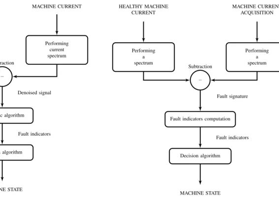
Spectral subtraction is broadly used in audio data processing in order to remove acoustic noise and for speech enhancement [10]–[12]. Up to now, for fault detection, the spectral subtrac-tion was only used as denoising method in order to improve robustness against noise of the failure indicators in electri-cal drives [13], [14]. Afterward, advanced signal processing techniques are used to detect electrical machine abnormal operating conditions (Fig. 1). In this paper, we propose to use spectral subtraction as the main tool for induction machines fault diagnosis. In particular, it will be used for bearing faults detection. Figures 1 and 2 show flowcharts illustrating the main differences between the technique in [14] and the
NOISE SIGNAL Learning noise spectrum MACHINE CURRENT Performing current spectrum − Subtraction Denoised signal Diagnostic algorithm Fault indicators Decision algorithm MACHINE STATE
Fig. 1: Spectral subtraction for denoising aims.
proposed approach. The proposed technique is well-suited for steady-state and constant speed induction machine operating conditions. It is only applied on stationary signals which means time independent frequency content. In this context, the proposed strategy allows the fault impact extraction from the stator current by subtracting the PSD of the healthy machine from the faulty machine one at all times.
The technique algorithm can be described as follows:
∙ Spectral estimation of the healthy signal �ℎ[�]
(base-line data) based on the Short Time Fourier Transform (�� ℱ� ) (1). The �� ℱ� of �ℎ[�] is defined as:
�ℎ(�, �) = � −1
∑
�=0
�ℎ[�]�[� − �]�−��� (1)
where �[�] is the window function and � is the number of samples. �∈ Ω corresponds to the time index. Finally, the spectrum of the healthy signal is computed by averaging the �� ℱ� with respect to time i.e.(2).
�(�) = 1 ∣Ω∣
∑
�∈Ω
∣�ℎ(�, �)∣ (2)
where∣Ω∣denotes the cardinal of the set Ω.
∙ Spectral estimation of the supervised machine current
signal ��[�] using �� ℱ� (3).The �� ℱ� of ��[�] is
defined as: ��(�, �) = � −1 ∑ �=0 ��[�]�[� − �]�−��� (3) HEALTHY MACHINE CURRENT Performing a spectrum MACHINE CURRENT ACQUISITION Performing a spectrum − Subtraction Fault signature Fault indicators computation
Fault indicators Decision algorithm
MACHINE STATE
Fig. 2: The proposed approach.
Where �[�] has been defined previously and � is the number of samples. �∈ Ω corresponds to the time index.
∙ Subtraction of the current spectrum of the healthy case
from the monitored machine current spectrum at each time � (4);
�(�, �) = ∣∣��(�, �)∣ − �(�)∣ ��(�,�) ∀� (4)
where �(�, �) =∕ (�ℎ(�, �)) and∕ is the angle of the
complex number �ℎ.
∙ Performing the Inverse Short Time Fourier Transform
(ℐ�� ℱ� ) to reconstruct the temporal signal �[�] from �(�, �) with the Overlap and Add algorithm [15].
∙ Computation of the fault indicator.
For an automatic fault detection, we propose criteria based on the results of the stator current spectral subtraction. Two criteria are studied which are the fault signature energy and the fault signature energy to healthy case energy ratio (5). The criteria chosen allow to decide whether the machine is operating under healthy or faulty state. Furthermore, it can be used to estimate the fault severity degree.
�= 1 � � −1 ∑ �=0 ∣�[�]∣2 �= ∑� −1 �=0 ∣�[�]∣2 ∑� −1 �=0 ∣�ℎ[�]∣2 (5)
III. SIMULATIONRESULTS
This section reports on the performance of the proposed approach on simulated data. Simulation were performed using coupled electromagnetic circuits induction machine model. In particular, eccentricity fault introduced by bearing failures have been simulated and stator current signal has been sampled and processed using the method proposed in this paper. A. Coupled Electromagnetic Circuits Induction Machine Mod-eling
The magnetic equivalent circuit method is one of the proven methods to model magnetic devices [16]. Many works in the literature have been devoted to the application of magnetic equivalent circuits method to model induction machines under healthy and faulty states [17], [18]. This approach is based on the induction machine analytical models. Inductances are calculated from the actual geometry and winding layout of the machine. This method is based on the following assumptions: �) negligible saturation; ��) negligible eddy current, friction and windage losses; ���) insulated rotor bars ��) no conduc-tive magnetic circuit. The induction machine electrical and mechanical equation system is given by (6).
⎧ ⎨ ⎩ � ��[�] = −[�] −1([�] + Ω � ���[�] ) [�] + [�]−1[� ] � ��Ω = 1 2�[�]� ( � ���[�] ) [�] −��Ω −�1Γ� � ����= Ω (6) Where : [� ] = [ [��] [0] ] [�] = [ [��] [��] ] [�] = [ [��] [0] [0] [��]] ] [�] = [ [���] [���] [���] [���] ]
All the relevant inductances matrices [�] are calculated using the winding function method [19].
B. Bearing Faults Detection
1) Bearing Failures Impact on Induction Machine Stator Current: In [20], it has been presented a model studying the influence of bearing damage on the induction machine stator current. The authors consider the generation of rotating eccen-tricities at bearing fault characteristic frequencies ��. These
eccentricities lead to periodical changes in the mechanical inductances which produce additional frequencies ��� in the
stator current. These frequencies are given by the following equation (7).
��� = ∣��± ���∣ (7)
where ��is the stator current frequency, and �= 1, 2, 3....
This model has been applied in several works dealing with bearing faults detection. The above model components are analyzed using spectral analysis in [21]. In [4], [22] time-frequency and time-scale methods are used to identify bearing faults by analyzing stator current based on the same model. Therefore, the [20] approach has been adopted to model bearing failure effects on induction machine stator current. In
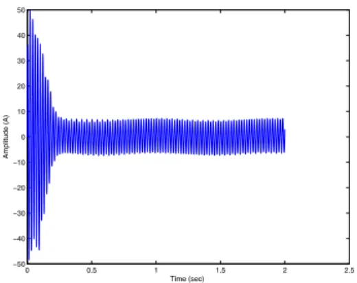
0 0.5 1 1.5 2 2.5 −50 −40 −30 −20 −10 0 10 20 30 40 50 Time (sec) Amplitude (A)
(a) Induction machine stator current with mixed eccen-tricity. 0 0.5 1 1.5 0 50 100 150 200 250 −50 −40 −30 −20 −10 0 10 20 30 40 50 Frequency (Hz) Time (sec) Amplitude (dB)
(b) Faulty induction machine stator current spectrogram.
Fig. 3: Faulty induction machine simulation signals.
particular, mixed eccentricities were used to emulate bearing fault in induction machine.
The stator current signals have been simulated during 2 second at 10��� sampling frequency with 10% mixed ec-centricity.
In this context, the simulation results are given by Fig. 3. It is obvious that the mixed eccentricity (modeling the bearing failure) introduces sidebands on the stator current. The following subsection describes the simulation results interpretation.
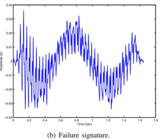
2) Mixed Eccentricity Detection Using Spectral Subtrac-tion: Spectral subtraction result is illustrated by Fig. 4. The fault signature is very noticeable in the case of bearing failure. The approach studied in this work performs well since it allows to extract the fault impact on the stator current: the signal components introduced by the induction machine bearing failure are observable (see Fig. 4b). The analysis of the figure 4 permits to conclude that the spectral subtraction gives good results: it allows to highlight the occurrence of abnormal operating conditions of the induction machine using stator current analysis. The simulation results has been confirmed using experimental data. The next section deals with the experimental results for bearing fault detection in induction machine. Particularly, the ball bearing fault has been investigated.
0 0.2 0.4 0.6 0.8 1 1.2 1.4 1.6 1.8 −0.4 −0.3 −0.2 −0.1 0 0.1 0.2 0.3 0.4 Time (sec) Amplitude (A)
Mixed eccentricity signal Healthy signal
(a) Healthy and mixed eccentricity failure stator cur-rents. 0 0.2 0.4 0.6 0.8 1 1.2 1.4 1.6 1.8 −0.04 −0.03 −0.02 −0.01 0 0.01 0.02 0.03 0.04 Time (sec) Amplitude (A) (b) Failure signature.
Fig. 4: Spectral subtraction on simulation stator currents.
IV. EXPERIMENTALTESTS
Experiments were conducted on induction machine with bearing failures in order to prove the effectiveness of the techniques described in the present work. The next subsections deal with the experimental results on ball bearing faults. A. Test Rig
The proposed approach performances are evaluated using experimental signals from a0.75−kW induction machine drive test bench (Fig. 5).
The induction machine bearings were artificially deterio-rated as shown by (Fig. 6). The experimental data has been established in a previous work by our research team [23]. B. Experimental Results Analysis
Bearing failures can be categorized into distributed and located defects. This paper is focused on single-point defects which are localized ones and can be classified according to the following affected elements: outer raceway, inner raceway, ball, and bearing cage [1]. The proposed spectral subtraction failure detector has been tested on the bearing failures depicted by Fig. 6. The measured stator currents for off-line analysis are acquired at 10 kHz by data acquisition card. Further signal post-processing is done on a standard desktop PC using
(a) (b)
(c) (d)
Fig. 6: Artificially deteriorated bearing: (a) outer race deterio-ration, (b) inner race deteriodeterio-ration, (c) cage deteriodeterio-ration, (d) ball deterioration.
Matlab. The following experimental validation is focused on the ball bearing defect (Fig. 6d).
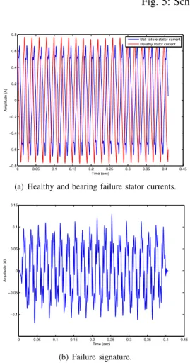
Figures 7 and 8 illustrate the spectral subtraction experi-mental application in case of a ball bearing defect. Indeed, it shows, the healthy stator current, the faulty stator current, and the resulting fault signature in time domain for an unloaded and loaded induction machine, respectively. This residue is used to compute the criteria proposed above.
0 0.05 0.1 0.15 0.2 0.25 0.3 0.35 0.4 0.45 −1.5 −1 −0.5 0 0.5 1 1.5 Time (sec) Amplitude (A)
Ball failure stator current Healthy stator current
(a) Healthy and bearing failure stator currents.
0 0.05 0.1 0.15 0.2 0.25 0.3 0.35 0.4 0.45 −0.25 −0.2 −0.15 −0.1 −0.05 0 0.05 0.1 0.15 0.2 0.25 Time (sec) Amplitude (A) (b) Failure signature.
Fig. 7: Spectral subtraction on experimental stator currents for unloaded machine.
Fig. 5: Scheme of the experimental set up. 0 0.05 0.1 0.15 0.2 0.25 0.3 0.35 0.4 0.45 −0.8 −0.6 −0.4 −0.2 0 0.2 0.4 0.6 0.8 Time (sec) Amplitude (A)
Ball failure stator current Healthy stator current
(a) Healthy and bearing failure stator currents.
0 0.05 0.1 0.15 0.2 0.25 0.3 0.35 0.4 0.45 −0.1 −0.05 0 0.05 0.1 0.15 Time (sec) Amplitude (A) (b) Failure signature.
Fig. 8: Spectral subtraction on experimental stator currents for 400� loaded machine.
Table I presents the chosen criteria to determine the in-duction machine healthy or faulty state under different load conditions. These criteria are the spectral subtraction residue energy and the healthy signal energy to residue energy signal
TABLE I: Fault indicators.
Criterion
Residue energy to healthy signal
energy ratio (10−4)
Residue energy (10−4)
Bearing Healthy Faulty Healthy Faulty
N� ���� 2.04 154 1.28 99
100� 7.18 142 4.23 83.9
200� 3.53 143 1.71 69.4
300� 1.27 102 0.423 34.6
400� 0.88 64.7 0.192 14.14
ratio. This table allows to conclude on the proposed approach appropriateness to determine the induction machine operating state. Additional tests have shown that these criteria are also well-adapted to the other bearing failures.
In the present work, the induction machine is supposed to operate under steady state conditions. Whereas, in the case where the operating conditions change (load variation for instance), a new baseline data should be retrieved and processed off-line. Then, the spectral subtraction can be ap-plied to diagnosis abnormal operating conditions (in our case bearing failure in squirrel-cage induction machine) for the new operating conditions.
V. SUMMARY
The spectral subtraction is based on the Fourier transform which means that the technique is limited by the Fourier transform resolution [24]. Despite this limitation, the proposed technique gives good results on simulated and experimental signals.
The general conclusions that can be drawn from these simu-lation and off-line experimental results are the effectiveness of
the proposed fault detection approach based on the stator time-frequency representation and spectral subtraction technique in steady-state. In the case where the stator current frequency content does not abruptly change, the proposed approach is assumed to be a well adapted tool to detect abnormal operating conditions in a non-stationary environment. Unfortunately, the spectral subtraction does not allow to distinguish the nature of the induction machine failure and the faulty component. Further investigations will be conducted to provide a spectral subtraction based technique allowing to distinguish faulty components. Moreover, a suited decision algorithm should be proposed to allow the automatic detection of a faulty machine using the fault indicators studied in the present work.
REFERENCES
[1] M. E. H. Benbouzid, “A review of induction motors signature analysis as a medium for faults detection,” IEEE Trans. Industrial Electronics, vol. 47, no. 5, pp. 984–993, October 2000.
[2] S. Nandi, H. A. Toliyat, and X. Li, “Condition monitoring and fault di-agnosis of electrical motors - a review,” IEEE Trans. Energy Conversion, vol. 20, no. 4, pp. 719–729, December 2005.
[3] M. E. H. Benbouzid and G. Kliman, “What stator current processing based technique to use for induction motor rotor faults diagnosis?” IEEE
Trans. Energy Conversion, vol. 18, no. 2, pp. 238–244, June 2003. [4] A. Lebaroud and G. Clerc, “Classification of induction machine faults
by optimal time-frequency representations,” IEEE Trans. Industrial
Electronics, vol. 55, no. 12, pp. 4290–4298, December 2010. [5] A. Bellini, A. Yazidi, F. Filippetti, C. Rossi, and G. Capolino, “High
frequency resolution techniques for rotor fault detection of induction machines,” IEEE Transactions on Industrial Electronics, vol. 55, no. 12, pp. 4200–4209, December 2008.
[6] E. H. El Bouchikhi, V. Choqueuse, M. E. H. Benbouzid, J. Charpentier, and G. Barakat, “A comparative study of time-frequency representations for fault detection in wind turbine,” in Proceedings of the 2011 IEEE
IECON, Melbourne (Australia), November 2011, pp. 3584–3589. [7] M. Blodt, J. Regnier, and J. Faucher, “Distinguishing load torque
oscillations and eccentricity faults in induction motors using stator current wigner distributions,” IEEE Trans. Industry Applications, vol. 45, no. 6, pp. 1991–2000, November/December 2009.
[8] B. Yazici and G. Kliman, “An adaptive statistical time-frequency method for detection of broken bars and bearing faults in motors using stator current,” IEEE Trans. Industry Applications, vol. 35, no. 2, pp. 442–452, March/April 1999.
[9] J.Pons-Llinares, J. Antonino-Daviu, M. Riera-Guasp, M. Pineda-Sanchez, and V. Climente-Alarcon, “Induction motor diagnosis based on a transient current analytic wavelet transform via frequency b-splines,”
IEEE Trans. Industrial Electronics, vol. 58, no. 5, pp. 1530–1544, May 2011.
[10] G.Yu, S. Mallat, and E. Bacry, “Audio denoising by time-frequency block thresholding,” IEEE Trans. Signal Processing, vol. 56, no. 5, pp. 1830–1839, May 2008.
[11] Y. Ephraim and D. Malah, “Speech enhancement using a minimum mean square short-time spectral amplitude estimator,” IEEE Trans. Acoustics,
Speech and Signal Processing, vol. ASSP-32, no. 6, pp. 1109–1121, December 1984.
[12] S. Boll, “Suppression of acoustic noise in speech using spectral sub-traction,” IEEE Trans. Acoustics, Speech and Signal Processing, vol. ASSP-27, no. 2, pp. 113–120, April 1979.
[13] I. Bozchalooi and M. Liang, “A joint resonance frequency estimation and in-band noise reduction method for enhancing the detectability of bearing fault signals,” Mechanical Systems and signal Processing, vol. 22, no. 4, pp. 915–933, May 2008.
[14] J. Dron, F. Boleas, and I. Rasolofondraibe, “Improvement of the sensi-tivity of the scalar indicators (vrest factor, kurtosis) using a denoising method by spectral subtraction: application to the detection of defects in ball bearings,” Journal of Sound and Vibration, vol. 270, no. 1-2, pp. 61–73, February 2004.
[15] M. Narasimha, “Modified ovelap-add and overlap-save convolution algorithms for real signals,” IEEE Signal Processing Letters, vol. 13, no. 11, pp. 669–671, November 2006.
[16] H. Toliyat and T. Lipo, “Transient analysis of cage induction machines under stator, rotor bar and end ring faults,” IEEE Trans. Energy
Conversion, vol. 10, no. 2, pp. 241–247, June 1995.
[17] G. Houdouin, G. Barakat, B. Dakyo, E. Destobbeleer, and C. Nichita, “A coupled magnetic circuit based global method for the simulation of squirrel cage induction machines under rotor and stator faults,” in
Proceedings of ELECTRIMACS’02, Montreal (Canada), August 2002, pp. 18–21.
[18] H. Toliyat, M. Arefeen, and A. Parlos, “A method for dynamic simula-tion of air-gap eccentricity in inducsimula-tion machines,” IEEE Trans. Industry
Applications, vol. 32, no. 4, pp. 910–918, July/August 1996.
[19] G. Joksimovic, M. Durovic, J. Penman, and N. Arthur, “Dynamic sim-ulation of dynamic eccentricity in induction machines-finding function approach,” IEEE Trans. Energy Conversion, vol. 15, no. 2, pp. 143–148, June 2000.
[20] R. Schoen, T. Habetler, F. Kamran, and R. Bartheld, “Motor bearing damage detection using stator current monitoring,” IEEE Trans. Industry
Applications, vol. 31, no. 6, pp. 1274–1279, November/December 1995. [21] J. Stack, T. G. Habetler, and R. G. Harley, “Bearing fault detection via autoregressive stator current modeling,” IEEE Trans. Industry
Applica-tions, vol. 40, no. 3, pp. 740–747, May/June 2004.
[22] L. Eren, K. Teotrakool, and M. Devaney, “Bearing fault detection via wavelet packet decomposition with spectral post processing,” in
Proceedings of the 2007 IEEE IMTC, Warsaw (Poland), May 2007, pp. 1–4.
[23] Y. Amirat, V. Choqueuse, M. E. H. Benbouzid, and S. Turri, “Hilbert transform-based bearing failure detection in DFIG-based wind turbines,”
International Review of Electrical Engineering, vol. 6, no. 3, pp. 1249– 1256, June 2011.
[24] L. Cohen, Time-Frequency Analysis. Englewood Cliffs, NJ:
Prentice-Hall, 1995.