HAL Id: hal-01184190
https://hal.archives-ouvertes.fr/hal-01184190
Submitted on 13 Aug 2015
HAL is a multi-disciplinary open access
archive for the deposit and dissemination of
sci-entific research documents, whether they are
pub-lished or not. The documents may come from
teaching and research institutions in France or
abroad, or from public or private research centers.
L’archive ouverte pluridisciplinaire HAL, est
destinée au dépôt et à la diffusion de documents
scientifiques de niveau recherche, publiés ou non,
émanant des établissements d’enseignement et de
recherche français ou étrangers, des laboratoires
publics ou privés.
A New Pre-emption Policy For MPLS-TE Networks
Imène Chaieb, Jean-Louis Le Roux, Bernard Cousin
To cite this version:
Imène Chaieb, Jean-Louis Le Roux, Bernard Cousin. A New Pre-emption Policy For MPLS-TE
Net-works. 15th IEEE International Conference on Networks (ICON2007), Nov 2007, Adelaide, Australia.
pp.394-399, �10.1109/ICON.2007.4444119�. �hal-01184190�
A New Pre-emption Policy For MPLS-TE Networks
Im`ene Chaieb and Jean-Louis Le Roux
France Telecom R&D, 2 Avenue Pierre Marzin Lannion 22307, France
Email:{imene.chaieb, jeanlouis.leroux}@orange-ftgroup.com
Bernard Cousin
IRISA universite de Rennes 1 Rennes 35042, France Email: [email protected]
Abstract— The pre-emption mechanism may be used in Multi
Protocol Label Switching Traffic Engineering (MPLS-TE) net-works in order to reduce the number of rejected tunnels during failure. But pre-emption may have an impact on the convergence time, and it is required to minimize the number of pre-emptions per tunnel. For that purpose this paper proposes a new emption policy allowing reducing or limiting the number of pre-emptions per tunnel, after a network failure. Two approaches are proposed: A pre-emption reduction approach where the least preempted tunnels are pre-empted in priority and a pre-emption limitation approach where a tunnel cannot be preempted more thanN times during a given period. Simulation results show that we can limit the maximum number of pre-emptions for a given tunnel to only one, without significantly diminishing the rejection reduction capabilities.
Keywords: MPLS Routing, Traffic Engineering, Quality of Service.
I. INTRODUCTION
Traffic Engineering (TE) is required for performance op-timization of operational networks. A major goal of Inter-net Traffic Engineering is to facilitate efficient and reliable network operations while simultaneously optimizing network resource utilization and traffic performances [1].
Multi Protocol Label Switching (MPLS) is a switching tech-nology where packets are forwarded based on a short, fixed
length, label inserted between layer 2 and layer 3 headers.
MPLS is well suited to TE thanks essentially to its Explicit Routing capabilities. MPLS-TE enables establishing explicitly routed paths that respect a set of traffic engineering constraints, using a constraint based routing mechanism that include topol-ogy discovery path computation and path signalling functions. Such explicit MPLS paths are called Traffic Engineering-Label Switched Paths (TE-LSP), they are characterized by a set of TE attributes such as bandwidth and priority that are used during path computation and signalling. The priority attribute is used for emption. An LSP with a given emption priority can empt an LSP with a lower pre-emption priority which is then rerouted on an alternate path if there is enough capacity. Pre-emption can be used for various applications, including bandwidth de-fragmentation, rejection reduction and service differentiation. In [2], the pre-emption mechanism is used to reorder LSP setup requests in order to improve network utilization and reduce the number of rejections during a network failure. It appears that an increasing bandwidth order minimizes the number of rejected LSPs during failure, and if lower bandwidth LSPs have a
higher priority they pre-empt higher bandwidth LSPs, and all happens as if lower bandwidth LSPs were setup before higher bandwidth LSPs. This solution improves significantly the performances of the CSPF (Constraint Shortest Path First) MPLS-TE routing algorithm in terms of rejection ratio. In return, pre-emption cascade effects may significantly impact the stability of the network and lead to longer convergence time. Several pre-emption policies are proposed to optimize one or more objective functions. In [3], authors propose a policy which combines the three main optimization criteria: Number of LSPs to be pre-empted, priority of LSPs to be pre-empted and the amount of bandwidth to be pre-empted. This paper proposes a new pre-emption policy that aims to minimize the number of pre-emptions per LSP with as key objective to reduce the convergence time upon network failure cases. The proposed pre-emption policy reduces or limits the number of pre-emptions experienced by a given LSP. In addition to the priority and bandwidth attributes, this policy requires to maintain another attribute indicating the number of times an LSP has already been pre-empted during a given period. The remainder of this paper is organized as follows: The pre-emption mechanism is reminded in section II. In section III, we define new pre-emption policies allowing to minimize the number of pre-emptions per LSP. This policy is then evaluated in section IV using several criteria. Last but not least the applicability of our approach is discussed in section V, before to conclude in section VI.
II. PRE-EMPTION MECHANISM
The RSVP-TE protocol [4] includes a pre-emption mechanism that allows an LSP with a given priority to pre-empt an LSP with a lower priority. The lower priority LSP is rerouted on an alternate path and all happens as if the lower priority LSP had been setup after the higher priority LSP. The RSVP-TE protocol specifies two priority attributes: the setup priority that specifies the capability of an LSP to pre-empt another LSP and the holding priority that specifies the capability of an LSP to resist to pre-emption.
Both priorities have a range of 0 (highest priority) to 7
(lowest priority). An LSP with a higher (numerically lower) setup priority can pre-empt an LSP with a lower (numerically higher) holding priority. To avoid continuous pre-emption and oscillations, the holding priority should never be lower (numerically higher) than the setup priority.
to advertise one Unreserved Bandwidth (UB) parameter per priority level [5], [6]:
UB = (UB(0), UB(1), ..., UB(7)), (0 <= i <= 7)
In order to compute the route for a LSP L with setup priority sp(L) and bandwidth requirement BW (L), only the unreserved bandwidth for priority sp(L) has to be checked. Thus, available bandwidth is checked by considering only the LSPs with same or higher priority and, as if LSPs with lower priority did not exist. Once the LSP is established, the Unreserved Bandwidth vector on a link is updated taking into account the holding priority hp(L) as follows:
If i >= hp(L) Then
UB(i) = UB(i) − BW (L), (0 <= i <= 7)
We distinguish hard and soft pre-emptions [7]: With hard pre-emption, pre-empted LSP is torn down before to be reestablished and this leads to traffic disruption, while with soft pre-emption, the pre-empted LSP is not immediately torn down, its ingress LSR is notified that a pre-emption will occur and it performs a make before break rerouting to let room for the higher priority LSP. Pre-empting an LSP may cause other emptions in the network, and this may lead to some pre-emption cascade effects, as the pre-empted LSP may itself pre-empt another lower priority LSP, and so on.
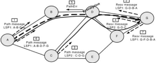
Let’s consider the example depicted in Fig. 1 to describe how the pre-emption mechanism operates. The figure shows a
network with 7 nodes and 9 bidirectional links. The capacity
of each link is50 M (M = 1Mbps). Two LSP setup requests
arrive successively as follows:
• LSP1 (L1): From node A to node G, BW(L1) = 50M,
(sp(L1), hp(L1)) = (7, 7).
• LSP2 (L2): From node C to node G, BW(L2) = 50M,
(sp(L1), hp(L2)) = (0, 0).
The LSP1 request arrives on node A first, the path A-B-D-G is computed by the CSPF algorithm. Then the RSVP-TE signalling starts, and (1) an RSVP P ath message travels from the source to the destination along the computed path. If there is sufficient bandwidth available on each link of the computed path, (2) a Resv message is sent from the destination node to the source node to distribute labels and reserve bandwidth. When the LSP2 request arrives on node C, C computes the constrained path, C-D-G. Because the setup priority of LSP2 is higher (numerically lower) than the holding priority of LSP1,
C consider that there are50M available on link D-G. (3) LSP2
signalling is then triggered, and (4) the Resv message for LSP2 arrives at D which detects that there is no sufficient available resources for both LSPs. LSP1 that has a holding priority lower that LSP2 setup priority is pre-empted, and
(5) the node D sends an RSVP P athError message with
a pre-emption notification towards node A (the head-end of LSP1). Upon receiving the pre-emption notification, node A recomputes a path, A-B-D-F-G, that can accommodate the LSP1 bandwidth, and (6)-(7) re-signals LSP1 along the new
path. In this example, when the pre-emption in node D is
A PathErr Path m essage LSP1: A-B-D-G 1 Resv m essage LSP1: G-D-B-A Path m essage LSP2 : C-D-G Path m essage LSP1: A-B-D-F-G B C D E F G Resv m essage LSP2: G -D-C Resv m essage LSP1: G-F-D-B-A 5 2 4 7 3 6 Preem ption
Fig. 1. Pre-emption Mechanism
triggered to setup the new LSP2, node D chooses to pre-empt LSP1 because it is the unique LSP with lower priority that crosses the link D-G. However, in a large network there may be a lot of LSPs that are candidate for pre-emption on a transit node. The transit node where pre-emption occurs has to choose one or more LSPs to be pre-empted. Such decision is usually taken according to one or more of the following objective functions [3]:
• Minimize the priority of pre-empted LSPs.
• Minimize the number of pre-empted LSPs.
• Minimize the pre-empted bandwidth.
This implies various pre-emption policies:
• R: Choose randomly the LSP(s) to be pre-empted.
• P: Pre-empt LSPs that have the lowest priority
(numeri-cally the highest).
• N: Pre-empt the minimum of LSPs: Sort pre-emption
candidate LSPs in decreasing bandwidth order.
• B: Pre-empt the minimum of bandwidth: Sort
pre-emption candidate LSPs in increasing bandwidth order. These policies are extensively discussed in [8] that also proposes a policy which combines all these policies. In the remainder of this paper, only R and P policies are used to compare with our policy. P is chosen it offers better results than other policies (in our case where priorities are assigned to LSPs according to their sizes [2]).
III. NEW PRE-EMPTION POLICIES
In this section, in addition to the existing pre-emption policies listed above, we propose new pre-emption policies that minimizes the maximum number of pre-emptions per LSP.
A. Motivations
In an MPLS-TE restoration mode, ingress routers have to reroute all the impacted LSPs upon network failure such as link or node failure. MPLS-TE pre-emption may be used during such rerouting in order to reduce the number of rejected LSPs [2]. The MPLS-TE convergence time, which is the delay between failure occurrence and the reestablishment of all LSPs impacted by the failure, have to be minimized in order to minimize the service disruption. Actually, this convergence time depends on the number of times a given LSP is empted. Hence minimizing the maximum number of pre-emptions per LSP allows reducing the global convergence time.
B. Proposed Policy
Actually with current RSVP-TE protocol [4], LSPs are characterized only by their bandwidth and priority attributes. So, transit routers have no any knowledge on the number of times a LSP has been pre-empted. To allow transit routers to know this information, we propose to maintain a certain number of pre-emption tokens per LSP that will be used in the pre-emption mechanism as follows:
• An LSP is initialized with a number of token
MaxT oken.
• Whenever an LSP is pre-empted, it looses a token.
• An LSP gains a token, after a period Tt.
• When there are several LSPs candidate for pre-emption,
LSPs with more tokens are preferred.
Two variants of this approach can be investigated when an LSP has no longer any token, Preeemption Limiter (P L) and Preemption Reducer (P R). With PL an LSP that has no longer any token cannot be pre-empted. However, with PR an LSP that has no longer any token can still be pre-empted. With PL we actually limit the maximum number of
pre-emptions per LSP during the period Tt to MaxT oken.
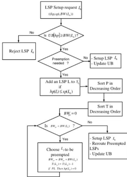
When pre-emption is needed to setup a new LSP (Ln), firstly
preemptable LSPs are added to SLp. The set of pre-emptable
LSPs SLp includes LSPs which traverse the current link and
whose holding priorities are lower than the setup priority of the new LSP priority. Then, we proceed to choose the set of one ore more LSPs that will be pre-empted. Firstly, LSPs are sorted in increasing order of their priorities (P policy) to reduce pre-emption cascading effect and so reduce the number of preemptions. Then, LSPs that have the most number of tokens are chosen to be pre-empted. We keep pre-empting in decreasing order of T (where T is the number of tokens of a
pre-emptable LSP), until BW(Ln) is satisfied. Whenever an
LSP is pre-empted, its number of tokens is decremented and in PL case, if the number of tokens of the pre-empted LSP reaches zero, then its holding priority will be set to zero (the highest priority) to avoid its pre-emption during the period
Tt (more details in section V). Fig. 2 shows a flowchart that
summarizes how the pre-emption mechanism operates using our policy.
IV. EVALUATION
In this section, we numerically evaluate our approach. All the simulations shown in the remainder of the paper are carried out using the network topology that was proposed in [9], see
Fig. 3. This topology includes 15 nodes and 28 bidirectional
links. The capacity of the light links is2.5∗103units and that
of the dark links is10∗103units (taken to model the capacity
ratio of OC-48 and OC-192 links and scaled by 100). All experiments are made under the following assumptions:
• We assume that all LSPs are long lived (”static” case).
• We construct a full mesh of LSPs between edge routers,
by loading the network with 840 LSPs = 15 ∗ 14 ∗ 4 =
Ner ∗ (Ner− 1) ∗ Nl, with Ner is the number of edge
Sort T in Decreasing Order Choose to be preempted - Setup LSP - Reroute Preempted LSPs - Update UB LSP Setup request )) ( ), , ((hpspBWLn Is ?UB[ ]hp≥BW(Ln) Reject LSP No Yes 0 = pr BW ) (p pr pr BW BWL BW= + Is ?BWpr<BW(Ln) 1 ) ( ) (Lp=TLp− T Add an LSP L to if No - Setup LSP - Update UB Sort P in Decreasing Order p L Yes Ln n L n L ) ( ) (L spLn hp ≤ n L S 0 ) (Lp= hp Then PL if n L Preemption needed ? No Yes
Fig. 2. Pre-emption algorithm using our policy
1 14 10 7 3 6 5 12 11 13 15 9 8 4 2
Fig. 3. The network topology
routers and Nlis the number of established LSPs between
each edge routers pairs.
• We multiply the LSP’s bandwidth by an increasing Traffic
Scale factor k to vary the network load conditions.
• For each value of k, we conduct 100 trials by
gener-ating randomly 840 requests with bandwidth demands
uniformly distributed between 1 and 200 units. The following metrics are used to evaluate our approach:
• Maximum number of Pre-emptions per LSP (MPL).
• Cumulated number of Pre-emptions (CP).
• Number of LSPs Preempted at least One time (LPO).
• Rejected LSPs Ratio (RLR), that is the number of rejected
LSPs divided by the number of requested LSPs.
• Rejected Bandwidth (RB): The cumulated amount of
bandwidth rejected.
A. PR: Pre-emption Reducer
1) MPL: Fig. 4 shows the maximum number of
pre-emptions per LSP (MPL) when using the new PR pre-emption
policy for MaxT oken = 1, 4, 7 against existing policies, R
and P, discussed in section II. We see that when MaxT oken increases, PR leads to a slight decrease of the MPL. For
50% over R policy and 9% over P policy, which is actually not a significant improvement. In fact, when MaxT oken value is
small, a lot of LSPs rapidly end up with0 tokens and hence the
token number does no longer allows discriminating between more pre-empted and less pre-empted LSPs. Note that PR for
MaxT oken = 4 performs as same as for MaxT oken = 7.
0.6 0.8 1 1.2 1.4 1.6 1.8 2 0 1 2 3 4 5 6 7 8 9
Maximum Number of preemption per LSP
k Random P PR (MaxToken=1) PR (MaxToken=4) PR (MaxToken=7)
Fig. 4. Maximum number of pre-emptions per LSP vs. k
B. PL: Pre-emption Limiter
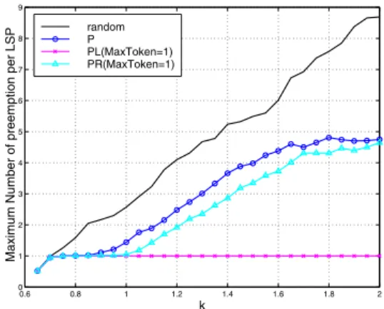
1) MPL: Fig. 5 shows that the MPL performances of
PL policy (for MaxT oken = 1, 2 and 3) are significantly
improved compared to R and P policies and this was expected because PL provides by definition a strict limitation of the
number of preemptions per LSP. For MaxT oken = 1 and
k = 2, PL attains a gain of about 88% over R policy and 79%
over P policy. As MaxT oken increases, the gain decreases. In fact, as we limit the number of pre-emptions per LSP to
MaxT oken, the MPL will be at most equal to MaxT oken.
Fig. 6 shows that, for MaxT oken = 1 and k = 2, the MPL
0.6 0.8 1 1.2 1.4 1.6 1.8 2 0 1 2 3 4 5 6 7 8 9
Maximum Number of preemption per LSP
k Random P PL (MaxToken=1) PL (MaxToken=2) PL (MaxToken=3)
Fig. 5. Maximum number of pre-emptions per LSP vs. k
performances of PL are of 79% better than those of PR. In
fact, the MPL performances of PL are guaranteed as we limit MPL to MaxT oken. However, using PR we cannot guarantee to limit MPL because a same LSP may be preempted as many times as necessary if there are no other pre-emptable LSPs. We find out according to the simulation results shown above
0.6 0.8 1 1.2 1.4 1.6 1.8 2 0 1 2 3 4 5 6 7 8 9
Maximum Number of preemption per LSP
k
random P
PL(MaxToken=1) PR(MaxToken=1)
Fig. 6. Maximum number of pre-emptions per LSP vs. k
that PL seems more relevant. It provides the best performances in terms of MPL. Hence, we will focus on PL approach in the remainder of the evaluation. So, let’s look at the impact of PL on other performance metrics.
2) CP: Fig. 7 illustrates the CP in the network. For MaxT oken = 1 and k = 2, PL reduces the CP by 57%
compared to R policy and by 11% compared to P policy.
We note that as MaxT oken increases, the probability that there are non pre-emptale LSPs decreases and hence, more pre-emptions are triggered.
0.6 0.8 1 1.2 1.4 1.6 1.8 2 0 50 100 150 200 250 300 350 400 450 500
Number of Total preemption
k Random P PL (MaxToken=1) PL (MaxToken=2) PL (MaxToken=3)
Fig. 7. Maximum number of pre-emptions per LSP vs. k
3) LPO: Fig. 8 shows that PL increases the LPO by23%
over P policy (for MaxT oken= 1, k = 2). This result is due
to the fact that as it limits to MaxT oken the number of pre-emptions per LSP, the policy tries to preempt other LSPs that have not already been preempted MaxT oken times. So, the number of LSPs that have been preempted at least one time is higher and increases when MaxT oken decreases but remains
always lower than R policy. Note that for MaxT oken= 1, the
number of LSPs pre-empted at least one time is equal to the total number of pre-emptions. Actually, our policy reduces the number of pre-emptions per LSP and hence equally spreads the pre-emption among all LSPs in the network.
4) RLR: Now, we focus on the rejection ratio. In [2],
pre-emption is used to dynamically reorder the setup of LSPs in increasing bandwidth order. This reordering reduces
signifi-0.6 0.8 1 1.2 1.4 1.6 1.8 2 0 50 100 150 200 250
Number of Different Preempted LSPs
k Random P PL (MaxToken=1) PL (MaxToken=2) PL (MaxToken=3)
Fig. 8. Number of LSPs pre-empted at least one time vs. k
cantly the rejection ratio compared to the CSPF and WSP (Widest Shortest Path) algorithms without pre-emption. In return, it increases slightly the amount of bandwidth rejected. The aim now is to check how PL impacts the benefits of the pre-emption based reordering approach defined in [2]. Fig. 9 shows that PL induces a slightly higher RLR than R and P policies - a price paid because the approach decides to reject an LSP request instead of preempting the same LSP more than MaxT oken times. As MaxT oken increases, the RLR
for PL becomes close to P and random cases. MaxT oken= 1
corresponds to the lowest rejection reduction that PL can
achieve. For this MaxT oken value and for k= 2, PL rejects
about 8% more than R policy and 6% more than P but still
leads to a rejection reduction of 26% over CSPF without
pre-emption and25% over WSP without pre-emption.
1.3 1.4 1.5 1.6 1.7 1.8 1.9 2 0 5 10 15 20 25
Ratio of Requests Rejected
k CSPF WSP Random P PL (MaxToken=1) PL (MaxToken=2) PL (MaxToken=3)
Fig. 9. Ratio of rejected LSPs vs. k
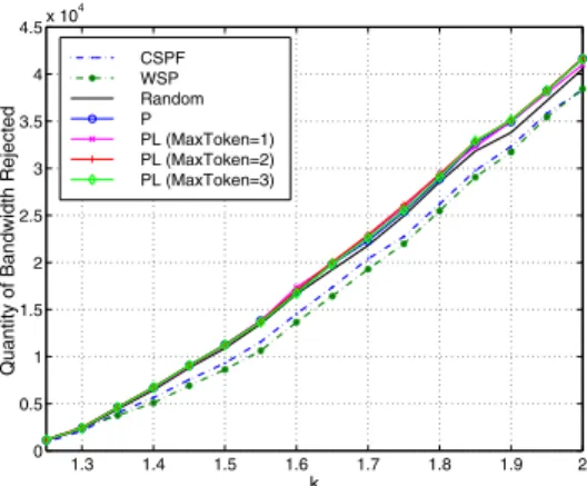
5) RB: Fig. 10 shows that PL does not increase significantly
the quantity of bandwidth rejected compared to P policy and random case.
We have seen that the PL procedure allows significantly reducing the maximum number of pre-emptions per LSP
(it can decrease from 4 to 1 in our example) and the
total number of pre-emptions while increasing a bit the number of preempted LSPs (18% in our example). PL also increases a bit the number of rejected LSPs compared to other pre-emption policies (6 − 8% in our example),
1.3 1.4 1.5 1.6 1.7 1.8 1.9 2 0 0.5 1 1.5 2 2.5 3 3.5 4 4.5x 10 4
Quantity of Bandwidth Rejected
k CSPF WSP Random P PL (MaxToken=1) PL (MaxToken=2) PL (MaxToken=3)
Fig. 10. Quantity of bandwidth rejected vs. k
but the capability of pre-emption to reduce the rejection ratio is not really affected, the gain compared to CSPF or WSP without pre-emption is still significant (26% in our example). We have tested our approaches using others network topologies. Table I shows the gain induced by PL
(MaxT oken= 1) over R and P policies according to the five
main evaluation metrics for three topologies. The first and second topologies (T1 and T2) are obtained using the Tiers topology generator [10] and have two different sizes: T1 (resp.
T2) includes 50 (resp. 100) nodes and 243 (resp. 425) links.
The third topology (T3) is an operational network topology
with34 nodes and 112 links. The gain is computed as follows:
gain = [F (policy) − F (LP )] ∗ 100/F (policy)
Where F denotes the evaluation metric and policy includes P or R. The negative values of the gain correspond to the case where PL is worse than P or R policies. It can be seen that
the MPL improvement of PL varies from 75% to 92% over
R policy and from 75% to 80% over P policy. According to
the LSPs rejection, the table shows that the RPR degradation
induced by PL is comprised only between2% and 4% over R
policy and between2% and 6% over P policy. The table shows
also that the RB degradation of PL is comprised between 0.04% and 1.2% over R policy and between 0.005% and 1% over P policy. These simulation results prove that when varying network topology and traffic matrix, the RLR and RB degradation with PL remains low, while the MPL gain is considerably high. The question which rises now is how to
T1 T2 T3 R P R P R P MPPL [%] 88 75 90 75 92 80 CP [%] 63 10 65 9.5 70 12 LPO [%] 34 −13 45 −11 31 −13 RPR [%] −6 −4 −2 −2 −3 −3 RB [%] −1.2 −0.6 −0.04 −0.005 −1 −1 TABLE I
adapt the MPLS-TE control plane in order to support the PL approach?
V. APPLICABILITY OF OUR APPROACH
Applying our policy which consists in limiting the maxi-mum number of pre-emption per LSP, requires some exten-sions to the existing MPLS-TE mechanisms. The head-end router is managing the number of pre-emption tokens for an LSP. Our policy is applied by transit routers, that must know the number of tokens. This requires extending the RSVP-TE protocol. This extension consists in introducing a new object in the RSVP-TE ”Path” message, the Token object, that carries the current number of tokens of the LSP. The simulation results
showed that for MaxT oken= 1 we can achieve good results
in terms of MPL, CP and RLR/RB. Actually the particular case
MaxT oken = 1 does not require any extension to
RSVP-TE. It just requires a specific processing upon pre-emption.
The procedure to support PL with MaxT oken = 1 is quite
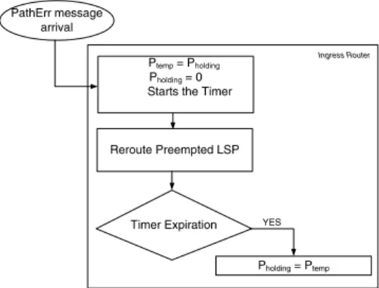
Ptemp = Pholding Pholding = 0 Starts the Timer
Reroute Preempted LSP Timer Expiration Pholding = Ptemp YES PathErr message arrival Ingress Router
Fig. 11. Flowchart for the additional processing on ingress router to implement our policy
simple: When an ingress router receives an RSVP-TE ”Path Error” with pre-emption notification to pre-empt an LSP with hold priority hp, it changes the holding priority of this LSP to
0 before to reroute the LSP, and starts a timer Tt. When the
timer expires the holding priority of the LSP goes back to its initial value hp. Hence, the LSP will be not pre-empted during
the period Tt (an LSP with hold priority (hp) 0 cannot be
pre-empted). Note that as we don’t change the setup priority, the capability of the LSP to pre-empt another LSP is not modified. This timer should be large enough to ensure that an LSP will not be pre-empted twice during a convergence phase upon failure, that is it must be larger than the convergence time. In return, it should remain lower than the minimum time between two failures, so as to allow the LSP to be pre-empted latter, during the next network failure event. Fig. 11 shows a flowchart that summarizes the additional processing required on ingress routers to implement our policy.
VI. CONCLUSION
During an MPLS-TE rerouting phase, upon network failure, pre-emption may be used to reduce the number of rejected LSPs. It is important during such pre-emption to minimize
the number of pre-emptions per LSP in order to minimize the convergence time and hence the service disruption. We have proposed a new pre-emption policy that aims to reduce the number of pre-emptions per LSP while keeping the capability of pre-emption to reduce the rejection. It consists in assigning to each LSP a given number of pre-emption tokens in addition to the bandwidth and the priority attributes. When an LSP is pre-empted it looses a token. When there are several candidate LSPs to be pre-empted, the LSPs that have more tokens are selected. In the PR variant, an LSP that has zero tokens can still be pre-empted while in the PL variant it can no longer be pre-empted which may lead to more rejections. Simulation results show that PL approach performs better than PR in terms of number of pre-emptions per LSP. It rejects a bit more LSPs than a basic pre-emption policy but the pre-emption remains efficient, as it still rejects much less LSPs than a solution without pre-emption. Results show also that when we limit the
number of pre-emptions per LSP to1, the maximum number
of pre-emption per LSP is minimized and the total number of pre-emptions is reduced. The benefits of pre-emption in terms of rejection are slightly reduced (6% more rejection in our example) but remain significant (26% less rejection than a solution without pre-emption, in our example). This specific
case (PL with MaxT oken= 1) is particularly interesting as
it does not require any extension to the RSVP-TE protocol. It simply requires a specific local procedure at ingress routers. Actually when an LSP is pre-empted its holding priority is
decreased to 0, and it goes back to its initial value after
a configured period. For future work, we will consider the implementation of this pre-emption strategy on a Linux MPLS router and we will evaluate its application in Generalized MPLS networks (GMPLS) for the placement of optical LSPs.
REFERENCES
[1] D. Awduche, J. Malcolm, J. Agogbua, M. O’Dell, and J. McManus, “Re-quirements for traffic engineering over MPLS,” RFC 2702, September 1999.
[2] I. Chaieb, J.L. Le Roux, and B. Cousin, “Improved MPLS-TE LSP path computation using preemption,” IEEE Global Information Infrastructure
Symposium (GIIS), 2007.
[3] J. Oliveira, C. Scoglio, I. Akyildiz, and G. Uhl, “New preemption policies for diffserv-aware traffic engineering to minimize rerouting in MPLS networks,” IEEE/ACM Transactions on Networking (TON), vol. 12, no. 4, pp. 733– 745, 2004.
[4] D. Awduche, L. Berger, D. Gan, T. Li, V. Srinivasan, and G. Swallow, “RSVP-TE: Extensions to RSVP for LSP tunnels,” RFC 3209, December 2001.
[5] D. Katz, K. Kompella, and D. Yeung, “Traffic engineering (TE) exten-sions to OSPF version 2,” RFC 3630, September 2003.
[6] H. Smit and T. Li, “Intermediate system to intermediate system (IS-IS) extensions for traffic engineering (TE),” RFC 3784, June 2004. [7] M. Meyer, J. Vasseur, and D. Maddux, “MPLS traffic engineering soft
preemption,” draft-ietf-mpls-soft-preemption-08.txt, October 2006. [8] J. Oliveira, J. Vasseur, L. Chen, and C. Scoglio, “LSP preemption
policies for MPLS traffic engineering.”
[9] T. L. M. Kodialam, “Minimum interference routing with applications to MPLS traffic engineering,” in INFOCOM, 2000.