HAL Id: hal-01657705
https://hal.inria.fr/hal-01657705
Submitted on 7 Dec 2017
HAL is a multi-disciplinary open access
archive for the deposit and dissemination of
sci-entific research documents, whether they are
pub-lished or not. The documents may come from
teaching and research institutions in France or
abroad, or from public or private research centers.
L’archive ouverte pluridisciplinaire HAL, est
destinée au dépôt et à la diffusion de documents
scientifiques de niveau recherche, publiés ou non,
émanant des établissements d’enseignement et de
recherche français ou étrangers, des laboratoires
publics ou privés.
Towards a Dynamic Adaptive Placement of Virtual
Network Functions under ONAP
Farah Slim, Fabrice Guillemin, Annie Gravey, Yassine Hadjadj-Aoul
To cite this version:
Farah Slim, Fabrice Guillemin, Annie Gravey, Yassine Hadjadj-Aoul. Towards a Dynamic Adaptive
Placement of Virtual Network Functions under ONAP. Third International NFVSDN’17O4SDI
-Workshop on Orchestration for Software-Defined Infrastructures), Nov 2017, Berlin, Germany.
pp.1-6. �hal-01657705�
Towards a Dynamic Adaptive Placement of Virtual
Network Functions under ONAP
Farah Slim
∗, Fabrice Guillemin
∗, Annie Gravey
+, and Yassine Hadjadj-Aoul
#∗
Orange Lab. (France),
+IMT Atlantique (France),
#University of Rennes 1 (France)
Abstract—In the context of the Open Network Automation Platform (ONAP), we develop in this paper a resource allocation strategy for deploying Virtualized Network Functions (VNFs) on distributed data centers. For this purpose, we rely on a three-level data center hierarchy exploiting co-location facilities available within Main and Core Central Offices. We precisely propose an active VNFs’ placement strategy, which dynamically offload requests on the basis of the load observed within a data center. We compare via simulations the performance of the proposed solution against mechanisms so far proposed in the literature, notably the centralized approach of the multi-site project within OpenStack, currently adopted by ONAP. It turns out that the proposed algorithm yields better performance in terms of both data center occupancy and overhead. Furthermore, it allows extending the applicability of ONAP in the context of distributed cloud, without requiring any modification.
I. INTRODUCTION
The emergence of Network Function Virtualization (NFV) deeply modifies the way networks are designed and operated. As a matter of fact, NFV allows network operators to instanti-ate network functions, where they are needed, and on demand according to customer’s needs. This is a groundbreaking innovation with respect to the current network architectures, where network functions are bound to the hardware. Virtu-alized Network Functions (VNFs) are thus instantiated on data centers as any other cloud applications. Many network functions are currently under consideration in the framework of NVF, notably mobile core functions, Radio Access Net-work (RAN) functions, etc. Moreover, netNet-work operators start offering to their customers (in particular business customers) the possibility of configuring their own network function with specific features1.
In order to support VNFs presenting strong latency re-quirements (such as RAN functions), network operators are considering the deployment of data centers close to end-users, typically at the edge of the IP backbone, or even deeper in the backhaul network. This can be done by co-locating computing and storage resources within geographical locations controlled by the network operators, at Core Central Offices (CCOs) and Main Central Offices (MCOs). It is worth noting that this trend also meets requirements of Multi-access Edge Computing (MEC) intended to host applications of service providers (e.g., content distribution networks) or customers (e.g., CPU offloading, in-network computing, gaming, etc.).
In this context, the challenge for network operators is twofold. On the one hand, they should offer to customers the
1http://www.orange-business.com/en/products/easy-go-network
possibility of designing on-line their sets of VNFs in order to build network services on the top of them. A demand by a customer appears, thus, as a service function chain (SFC) with requirements in terms of network resources and performance objectives (e.g., latency). On the other hand, once a set of VNFs is specified by the customer, the network operator has to place the requested VNFs by taking into account their requirements in terms of latency and network resources as well as their chaining.
A complete framework for the dynamic design and instan-tiation of VNFs has been elaborated by the ECOMP initiative [1]. This framework is the basis of the new Open Network Automation Platform (ONAP)2. This latter is composed of several blocks, from the service/VNF creation studio to the deployment on compute, storage and network resources. In particular, ONAP offers a unified view of all types of re-sources. For this purpose, the ONAP orchestrator schedules and implements tasks on the basis of rules and policies to create VNFs and reserve physical resources. This task requires the design of resource allocation algorithms. Since storage and compute resources are managed by OpenStack3
and network resources are managed by OpenDaylight4, the
ONAP orchestrator has to build up an abstraction of resources on the basis of the information available through these two management platforms. The resource allocation algorithms, then, have to use this abstraction to allocate resources to SFCs. This general problem has been widely studied in the techni-cal literature in the past few years in the framework of cloud computing by considering only storage and compute resources. Bandwidth allocation in networks has been studied for decades in the technical literature. The combination of network and cloud resources is, however, a more recent problem and many issues are still open. Cloud platforms in general do not consider the network interconnecting the various data centers and the network considers these data centers as clients and ignores their specific requirements in terms of performance.
In this paper, we examine the placement of SFC requests in the framework of ONAP when the network operates many data centers at its border. These data centers are intended to host VNFs and customer’s applications with stringent latency requirements. In addition, we assume that the network is also equipped with data centers, which can support VNFs or
2https://www.onap.org 3https://www.openstack.org/ 4https://www.opendaylight.org/
applications tolerant to delays up to a certain limit. In this framework, we basically split an SFC into two parts: one with strict delay requirements and the other more tolerant to delays. The paper is organized as follows. Section II reviews some orchestration solutions and resource allocation strategies in the framework of NFV. Section III recalls the overall ONAP architecture. In section IV, we set the design principles for resource allocation in NFV environment and introduce our resource allocation strategy. In Section V, we evaluate the per-formance of the proposed strategy. Some concluding remarks are presented in Section VI.
II. RELATEDWORK
Several NFV orchestration projects have been initiated with the idea of being compliant with the MANO (Management And Orchestration) reference architecture delivered by ETSI NFV [2]. The main objective of the CORD (Central Office Re-architected as a Data Center) orchestration solution for NFV environment is to bring elasticity and cloud agility to the telco Central Office [3]. From an architectural point of view, CORD has defined its own architecture but most of the architectural blocks might be mapped to the MANO reference architecture. CORD is based on the ONOS SDN controller to manage network resources [4]. With regard to resource allocation, CORD platform delegates VNF placement to the infrastructure controller, the so-called VIM (Virtual Infrastructure Manager), notably based on the Openstack platform. Gigaspaces Cloudify project5 was originally introduced to orchestrate application deployment in a cloud similarly to the Openstack’s Heat orchestrator. Later, with the emergence of NVF, a Telecom Edition was delivered including NFV-related use cases.
Each orchestration solution has defined its own architecture and objectives, but the main technical challenge is the same: Provisioning an end-to end network service that involves the creation of an IT infrastructure followed by the instantiation of all its necessary components. Hence, placement and resources’ allocation algorithms for NFV environment must be developed and encapsulated within the resource allocation engine, which is a core component of the NFV orchestration solutions.
Many works in the technical literature have studied the prob-lem of resource allocation in NFV networks. In [5], the authors describe a solution for the automatic placement of virtual functions involving a monitoring module and a placement’s engine, which is in charge of making the placement decision based upon the data collected by the monitoring component. Three placement engines based on available resources’ metrics were evaluated in terms of allocated requests into a centralized infrastructure composed of three hosts or physical machines. This work, however, does not consider the placement across multiple data centers and does not support the multi-site scenario, which is a critical requirement for managing NFV dedicated infrastructure.
In [6], the authors provide an NFV network model con-sidering the VNF chain routing as an optimization problem
5https://www.gigaspaces.com/cloudify-overview
and providing a mixed integer linear programming formulation (MILP) to resolve it. This formulation is multi-objective and aims at minimizing costs as well as the maximal link utilization, which was considered as a performance indicator. However, since no expected runtime complexity has been evaluated, this solution might be very time consuming and may not correspond to the agility and reactivity aspects of NFV.
A similar approach was adopted in [7] to resolve the VNF orchestration problem by providing an Integer Linear programming (ILP) formulation. Although the authors have proved that the time needed to evaluate the model increases more or less linearly with the number of service chain requests, this approach requires all requests to be known in advance and seems to be unable to manage rapid fluctuations of demand.
In the present paper, on the contrary, we focus on on-line and scalable orchestration to dynamically solve the resource allocation problem. Such a context has already been consid-ered in the technical literature. For instance, to address the problem of system size, the authors in [8] provide a dynamic programming based heuristic and evaluate performance in terms of execution time and costs. In our approach, we adopt, however, a different architectural view point by incorporating the notion of resource allocation in edge data centers, in order to meet several performance requirements such as e.g. latency. In addition to latency, we also claim that blocking is a key performance metric that has to be evaluated since edge data centers shall likely have a smaller capacity than the current centralized data centers with almost infinite capacity. In this context, we focus on a multi-site scenario, where data centers are geographically distant. Moreover, we consider placement, which is not based on infrastructure monitoring metrics; this choice is intended to simplify the global operation and thus to reduce overhead costs.
III. ONAPOVERALL ARCHITECTURE
To accelerate the transition to NFV, several projects have recently emerged to orchestrate VNFs inside a network. The newly formed project ONAP was created by merging two of the largest open source networking initiatives: ECOMP and Open Orchestrator project (Open-O). By taking benefits of both projects, ONAP is based on a unified architecture and implementation to deliver an open platform enabling end users to create their own VNFs. The platform aims at automating, orchestrating and managing VNFs and network services.
A. Architecture description
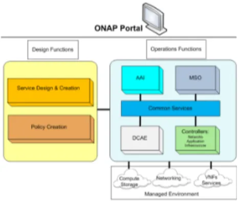
The ONAP project has defined its own unified architecture (see Fig. 1 ) and communication logic across its components. The main advantage of the ONAP platform is the flexible and scalable architecture, which supports the addition of new components. From a general point of view, the complete ONAP architecture can be split into two basic groups: the ONAP Design Time Framework and the ONAP Execution Time Framework. The main role of the design time frame-work is to describe the design functions through the ONAP
Portal. Basically, this component defines recipes for instan-tiating, monitoring and managing VNFs and services. It is also responsible of the distribution of these specific design rules into the execution time component. The execution time framework contains meta-data driven modules enabling VNF configuration and instantiation, and delivers real-time view of available resources and services.
To further analyze the ONAP architecture, we take a closer look at the two components described above. First, the design time framework consists of the following subcomponents:
1) Service Design and Creation (SDC): This is the ONAP design tool. Based on meta data description, SDC is an environment that entirely describes how VNFs or services are managed. It also describes multiple levels of assets, including resources and services described by means of resources’ requirements.
2) Policy Creation: This subsystem of ONAP contains a set of rules defining control, orchestration and manage-ment policies. VNF placemanage-ment rule is the policy that specifies where VNFs should be placed respecting some constraints.
Fig. 1. ONAP Simplified Architecture.
Secondly, the execution time framework is composed of: 1) Active and Available Inventory (AAI): The AAI is
con-tinually updated to provide a real-time view of the topology and the underlying available resources. 2) Controllers: A controller is in charge of managing
the state of a single resource. ONAP uses multiple controllers to execute resource’s configuration and in-stantiation, such as the Network Controller to configure the network and to manage VNFs or the Application Controller to manage more complicated VNFs and ser-vices. Both controllers are based on the Opendaylight platform. An additional controller is used for infrastruc-ture’s orchestration, in particular, to manage resources within the cloud’s infrastructure.
3) Master Service Orchestrator (MSO): From the top level, the MSO handles capabilities of end-to-end service provisioning. This master orchestrator is based on the underlying controllers described above.
4) Data Collection, Analytics and Events (DCAE): The primary role of the DCAE is to collect telemetry from VNFs and deliver a framework for analytic applications
to detect network anomalies and publishes corrective actions.
B. Resource allocation in ONAP
In the current ONAP architecture design, placement deci-sions are made by the single infrastructure controller, namely Openstack. Based on a heuristic algorithm, Openstack sched-uler favors those servers with the largest amount of available resources. To perform a placement request, the Openstack con-troller first collects informations stored in the AAI component in order to take the appropriate placement decision. Once this decision is made, the placement execution is also done by the same subsystem, notably the execution time component.
It is worth noting that the ONAP architecture handles the VNF placement and the resource allocation in a centralized fashion. The current implementation does not support any multi-site features, since resource allocation is made without taking geographical location into account. Furthermore, Multi-VIM is not supported; this means that no constraints on which cloud and which site the elements of a VNF should be placed can be specified.
The ONAP community is aware of the fact that both multi-site and multi-VIM are fundamental requirements of service provisioning. To revisit the scheduling logic, the present paper proposes a solution to allowing each placement demand to be characterized with geographical and administrative constraints to support multi-site and multi-VIM frameworks.
IV. PROPOSAL: ADYNAMIC ADAPTIVENFVOFFLOADING STRATEGY FORONAP
A VNF is in general composed of several components (also called sub-functions or microservices), which execute tasks located at different functional levels of the network, some being part of the data plane (i.e., manipulate user’s packet data streams), while some others are part of the control plane of the network. This can be illustrated for a virtual Evolved Packet Core (vEPC): Mobility Management Entity (MME) and Home Subscriber Server (HSS) are in the control plane while Servicing/Packet Gateway (S/PGW) are part of the data plane. A. Taking into account the performance requirements
Data plane components may present stringent requirements in terms of latency in order not to introduce unacceptable delays in the delivery of data. These components should preferably be instantiated along the data path, which is fixed by the routing algorithm. This is typically the case for RAN functions, which could be placed at different data centers but definitely along the data path (say, in a BBU hostel for encoding/decoding functions) and in a regional data centers for RLC and PDCP functions. Components with similar goals (e.g., firewalls) could be co-located to prevent unnecessarily delays by placing them at geographically distant locations; this could be required in order to meet global latency objectives.
Control plane components may be more tolerant to delays and could be placed in more centralized cloud platforms. This is notably the case of some functions of the mobile core (e.g., HSS, AAA, etc.).
B. Taking into account the network architecture
The distributed data centers deployed by network operators could be organized into three levels. The first level (edge level) is close to end-users, typically providing the IP edge of the network. This level could be installed within MCOs in order to host data plane functions, such as Deep Packet Inspection, Firewalls, S/P Gateways, some RAN functions, etc.
Note that the most recent advances in optical technology enables the migration of the current Central Offices (COs), notably hosting Optical Line Terminations, higher in the network, namely in MCOs. The same also applies for radio access, via the separation of Remote Radio Head and Base band Unit functions. Higher concentration levels enable better coordination of resources between access areas and are made possible by the ever growing capacities of High Performance Computing (HPC) platforms.
The second level (regional level) could be installed within the CCOs and would be equipped with important storage and computing capacities in order to host service platforms, CDN servers and some control plane VNF components that would benefit from being distributed (e.g. mobility support). The CCOs are already the current location of the regional PoPs that are deployed at the current edge of a nationwide IP network used by fixed access end-users.
The third level (nationwide level) would be centralized very high in the backbone IP network. Its data centers could host non delay-sensitive applications, regular cloud applications and control plane VNF components that would benefit from being centralized (e.g., HSS).
As mentioned above, MCOs will host data plane VNFs but are also good candidates for hosting MEC applications. Note that it is also possible to envisage the implementation of MEC capacities even closer to end users, say in COs or even in eNodeBs but at a much higher cost [9]. Another trend regarding the future architecture of 5G networks is the so-called Cloud RAN or Centralized RAN (C-RAN). In this architecture, the fronthaul links BroadBand Units (BBUs) and the Radio Units co-located with the antennas. BBUs would be grouped within “BBU hostels” located deeper in the network than the antennas, typically at MCOs. These elements are, thus, to be considered as likely candidates to host BBU hostels, MEC host platforms and edge level data centers.
As long as the end-user does not move from the area controlled by a given MCO, a data plane VNF component should not be displaced as it would increase the consumed bandwidth in the network and increase the latency of the global VNF. MEC applications on the the contrary could be displaced up to a certain limit depending on the application’s latency requirements. Displacement could also be applied to control plane VNF components, which could also be hosted either in CCOs or central data centers.
C. Resource allocation scheme
In view of the previous section, we can reasonably sup-pose that at the scale of a nationwide network (typically an Autonomous System of a Tier 2 IP network), we have a
system with three hierarchical levels of data centers: MCOs, CCOs and centralized data centers. While it is natural to suppose that centralized data centers have huge capacity, CCOs and MCOs may have more limited capacities (because of their number) and will certainly have to implement resource allocation schemes. Moreover, as discussed above MCOs and CCOs will have to cope with two kinds of requests:
• VNFs, which can be split between MCOs (for data plane functions) and CCOs or even centralized data centers (for control plane functions);
• MEC applications, which can be displaced while respect-ing possibly tight time constraints.
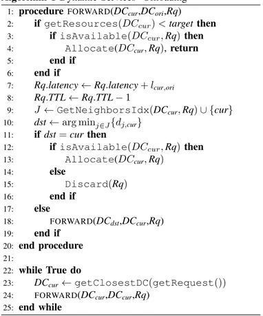
We then propose a resource allocation algorithm, which favors the placement of data plane VNF, while possibly offloading MEC applications (by exploiting the fact that they can be displaced up some certain limits). For this purpose, we introduce a target threshold, which is automatically adjusted according to the arrival rates of the different type of requests. When the occupancy of an MCO or a CCO is above a given threshold, a request is deflected to neighbors as specified in Algorithm 1.
The Distributed resource allocation algorithm that we pro-pose is as follows:
1) When a request arrives in the system using the getRequest function, the central dispatcher selects and redirects it to the edge data center, which is the closest to the origin of the request, using the getClosestDCfunction.
2) If the request cannot be accommodated by this edge data center (i.e., when the average resources obtained with getResources exceeds the target), then it is forwarded to one of its neighbors, which may respect the services’ time constraints.
3) To forward the request, the edge data center takes into account the number of redirections received from its neighbors and the time constraints of the request6.
Specifically, an edge data center maintains a counter, which records the moving average number of deflected requests from its neighboring edge data centers and its own requests’ deflection. The edge data center with the smaller number of deflected requests is chosen. If the data center selects itself, it handles the request (using the Allocate function).
4) The redirected request is examined by the edge data center, the request is forwarded to. If the request can still not be accommodated, then the previous step is repeated otherwise the request is discarded using the Discard function.
The target threshold is continuously adjusted by using a classical hysteresis principle between a maximum and a minimum value. Indeed, whenever the average load of the data center exceeds the maximal threshold, the target is reduced to augment deflections. Similarly, when the average load is
6The current data center selects a sub-list of data centers respecting the
below the minimal threshold, the target is increased to reduce deflections.
Algorithm 1 Dynamic Services’ Offloading
1: procedure FORWARD(DCcur,DCori,Rq)
2: if getResources(DCcur) < target then
3: if isAvailable(DCcur, Rq) then
4: Allocate(DCcur, Rq), return
5: end if
6: end if
7: Rq.latency ← Rq.latency + lcur,ori
8: Rq.TTL ← Rq.TTL − 1
9: J ← GetNeighborsIdx(DCcur, Rq) ∪ {cur}
10: dst← arg minj∈J{dj,cur}
11: if dst = cur then
12: if isAvailable(DCcur, Rq) then
13: Allocate(DCcur, Rq) 14: else 15: Discard(Rq) 16: end if 17: else 18: FORWARD(DCdst,DCcur,Rq) 19: end if 20: end procedure 21: 22: while True do 23: DCcur← getClosestDC(getRequest())
24: FORWARD(DCcur,DCcur,Rq)
25: end while
V. PERFORMANCEEVALUATION
The performance evaluation of our strategy has been done via simulations using a discrete event simulator implemented in MATLAB. We compared results obtained from our strat-egy to those obtained from the Openstack stratstrat-egy currently adopted by the ONAP platform.
A. Simulation settings
To simulate the decentralized cloud, we have considered the realistic network of Orange consisting of three level: Edge level (MCO), regional level (CCO) and nationwide level (Centralized Cloud Platform). MCO is about 100 km from CCO that is connected to a big centralized data center at a distance of 300 km7. We have considered N = 21 data
centers with different capacities deployed into the three levels described above. The system under consideration as well as Availability Zones defined for the Openstack strategy are illustrated in Fig. 2.
We have considered 3 types of requests, which arrive according to Poisson processes and require to be executed at different functional levels of the network. Data centers hosted at the MCO level might intercept the 3 different types of requests: (1) Data plane functions that must be
7Geographical locations and real distances are not mentioned in this paper
for the sake of confidentiality
Fig. 2. Network topology.
installed only within MCOs; (2) Control plane functions and MEC applications that are more delay tolerant and might be displaced if needed.
Apart from the data plane functions, centralized cloud platform and data centers deployed at the CCO level intercept control plane functions and MEC applications considered very volatile when compared with VNF, with larger arrival rates of requests and shorter holding times of resources. Requests are expressed in terms of CPU only. Results can be generalized to multiple resources scenario as we demonstrated in our previous work [10].
The global load of the system (data centers) is defined as
ρdef= 1 N N X j=1 ρj Cj where ρj def
= λj/µj is the load of Data Center j (for short,
DCj) with capacity Cj and λj and 1/µj represent the arrival
rate and the exponentially distributed holding time of resources at DCj, respectively. Data centers (DCs) are unevenly loaded; we only consider the global load ρ of the system given that some DCs are overloaded while some others are underloaded. In the simulations, we have taken the capacities of MCOs equal to 200 CPU units, that of CCOs to 500 CPU units and that of the centralized data center equal to 800 CPU units.
In order to compare our strategy against that currently used in ONAP, basically the Openstack strategy, we introduce the average blocking rate of requests defined as the fraction of requests, which are eventually rejected by the system:
β = 1 Λ N X j=1 λjβj where Λ = PN
j=1λj is the global arrival rate and βj is the
blocking rate of requests originally arriving at DCj. More precisely, βj is the fraction of requests, which are originally
arriving at DCj but eventually not accepted by the system (even after deflection).
B. Results and Discussion
Figure 3 compares the average blocking rates for control plane functions under our strategy while setting static and dynamic adaptive threshold against those obtained with the Openstack strategy. Static thresholds are set equal to 90 % of the capacity of the data center. This figure displays the
blocking probability versus traffic intensity and simulation results are averaged to obtain confidence intervals with a 95% confidence level. The results show that our strategy significantly reduces blocking of requests when compared to the Openstack one specifically when the system is overloaded. The more the system is loaded, the better performance is obtained. Figure 4 shows that results are qualitatively the same for MEC applications.
1 1.2 1.4 1.6 1.8 2 0.1 0.2 0.3 ρ β Static Threshold Dynamic Threshold Openstack
Fig. 3. Blocking rates for Control Applications.
1 1.2 1.4 1.6 1.8 2 0.1 0.2 0.3 ρ β Static Threshold Dynamic Threshold Openstack
Fig. 4. Blocking rates for MEC Applications.
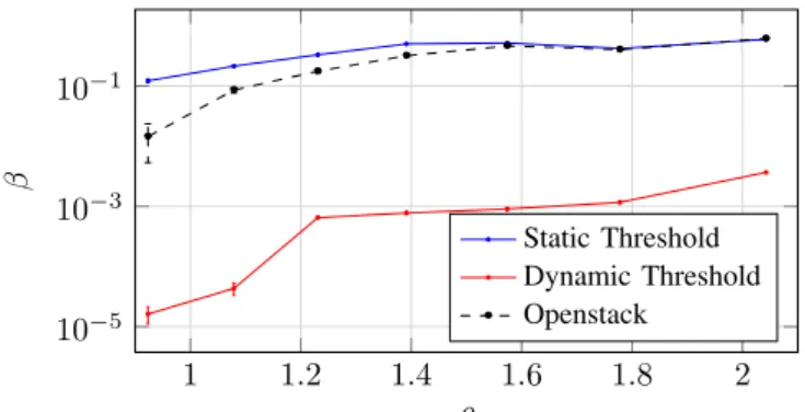
Figure 5 shows that our strategy with dynamic threshold yields the best performance for data plane functions. This is explained by the fact that thresholds are limiting the acceptance of MEC and control plane applications in data centers hosted at the CCO level and favors the placement of data plane functions at this level.
1 1.2 1.4 1.6 1.8 2 10−5 10−3 10−1 ρ β Static Threshold Dynamic Threshold Openstack
Fig. 5. Blocking rates For Data Plane Functions.
Figure 6 shows the variation of the load within a data center as well as the variation of the corresponding target threshold
under our dynamic adaptive offloading strategy. We verify that the threshold value is adapting dynamically as a function of the load conditions during the simulation time.
Fig. 6. Adaptive threshold variation according to the current load
VI. CONCLUSION
Considering the future “in network” cloud computing infras-tructure, we have proposed in this paper a potential solution for dynamic placement of VNFs, which can be directly used in the context of ONAP without any adjustment. Contrary to the current approach of VNF’s placement within ONAP, our solution takes into account latency and geographical constraints. This makes it possible to manage distributed cloud infrastructures with ONAP. Our results show that the proposed scheme improves the performance in terms of VNFs acceptance while requiring less overhead when compared to the Openstack-based approach adopted in the current version of ONAP.
REFERENCES
[1] AT&T, “Ecomp(enhanced control, orchestration, management and pol-icy) architecture white paper,” 2016.
[2] M. Ersue, “Etsi nfv management and orchestration-an overview,” in Proc. of 88th IETF meeting, 2013.
[3] A. Al-Shabibi and L. Peterson, “Cord: Central office re-architected as a datacenter,” OpenStack Summit, 2015.
[4] P. Berde, M. Gerola, J. Hart, Y. Higuchi, M. Kobayashi, T. Koide, B. Lantz, B. O’Connor, P. Radoslavov, W. Snow, and G. Parulkar, “Onos: Towards an open, distributed sdn os,” in Proc. of the Third Workshop on Hot Topics in Software Defined Networking, ser. HotSDN ’14. New York, NY, USA: ACM, 2014.
[5] S. Clayman, E. Maini, A. Galis, A. Manzalini, and N. Mazzocca, “The dynamic placement of virtual network functions,” in Network Operations and Management Symposium (NOMS). IEEE, 2014, pp. 1–9. [6] B. Addis, D. Belabed, M. Bouet, and S. Secci, “Virtual network
functions placement and routing optimization,” in Cloud Networking (CloudNet), 2015 IEEE 4th International Conference on. IEEE, 2015, pp. 171–177.
[7] H. Moens and F. De Turck, “Vnf-p: A model for efficient placement of virtualized network functions,” in Network and Service Management (CNSM), 2014 10th International Conference on. IEEE, 2014, pp. 418–423.
[8] M. F. Bari, S. R. Chowdhury, R. Ahmed, and R. Boutaba, “On orches-trating virtual network functions,” in Network and Service Management (CNSM), 2015 11th Int. Conf. on. IEEE, 2015, pp. 50–56.
[9] S.-E. Elayoubi and J. Roberts, “Performance and cost effectiveness of caching in mobile access networks,” in Proc. of the 2Nd ACM Conf. on Information-Centric Networking, ser. ACM-ICN ’15. New York, NY, USA: ACM, 2015, pp. 79–88.
[10] F. Slim, F. Guillemin, and Y. Hadjadj-Aoul, “On virtual network functions placement in future distributed edge cloud,” in 6th Int. Conf. on Cloud Networking (CloudNet). IEEE, 2017.