HAL Id: hal-02042821
https://hal.archives-ouvertes.fr/hal-02042821
Submitted on 3 Apr 2019HAL is a multi-disciplinary open access archive for the deposit and dissemination of sci-entific research documents, whether they are pub-lished or not. The documents may come from
L’archive ouverte pluridisciplinaire HAL, est destinée au dépôt et à la diffusion de documents scientifiques de niveau recherche, publiés ou non, émanant des établissements d’enseignement et de
Scott Delbecq, F. Tajan, Marc Budinger, Jean-Charles Maré, Florian Sanchez
To cite this version:
Scott Delbecq, F. Tajan, Marc Budinger, Jean-Charles Maré, Florian Sanchez. A framework for the conceptual and preliminary design of embedded mechatronic systems. 6th International Workshop on Aircraft System Technologies (AST 2017), 2017, Hamburg, Germany. �hal-02042821�
AST 2017, February 21–22, Hamburg, Germany
A FRAMEWORK FOR THE CONCEPTUAL &
PRELIMINARY DESIGN OF EMBEDDED MECHATRONIC
SYSTEMS
Scott Delbecq1, Florent Tajan2, Marc Budinger2, Jean-Charles Mare2, Florian
Sanchez2
1Institut Clément Ader, UMR CNRS 5312, Safran Electronics & Defense, Massy,
France
2 Institut Clément Ader, UMR CNRS 5312, INSA, Toulouse, France
Abstract
This paper presents a Python framework for the preliminary design of embedded mechatronic systems. Mechatronic systems have the particularity to involve several levels of design and several technologies. In addition, embedded systems introduce to the design problem specific constraints like energy consumption, resistance/impact to/on environment, mass, geometrical integration and reliability. In order to support the designer in satisfying these constraints, a Model-Based Design methodology and corresponding framework is proposed. Models used during preliminary design of such multi-domain systems come from several disciplines and have different scales: distributed parameters (3D Finite Element Method (FEM), 3D Computer Fluid Dynamics (CFD)) for local level, lumped parameters (1D/0D, Ordinary Differential Equation (ODE), Algebraic Differential Equations (ADE)) and state machine for global level. The dynamic simulation through 0D-1D models of the system to be designed is commonly used to validate architectural choices and preliminary sizing that require multi-disciplinary optimization. Unfortunately, optimization can not only apply to the system level and resort to 3D models cannot be avoided, even during the early design phases. The proposed framework aims at implementing the optimization loops at both local and global levels in an open source environment. It will be illustrated through a case study that deals with the preliminary design of a linear electromechanical flight control actuator.
Keywords: Acausal models, Design tools, Dynamic models, Electromechanical actuator, Model-Based Design, Multidisciplinary Design Optimization (MDO), Preliminary Design, Surrogate models.
1 INTRODUCTION
Preliminary design of an aircraft system or equipment requires a specific approach. Indeed, these specific mechatronic systems are characterized by a strong coupling between the domains of their components while having to satisfy design constraint such as system requirements or component technological limits. Moreover, different technologies are available for a given component. Thus, one part of the design problem
is to select the most appropriate technology regarding system requirements and costs but also integration and maintenance for the chosen architecture. The first part of this paper describes the typical problems encountered while designing mechatronic systems and how the framework could solve them. The second part describes dynamic models and methods used during the preliminary design of an electromechanical primary flight control actuator. Finally, the design of a linear electromechanical actuator (EMA) for aileron is achieved using MDO with the particularity to consider the dynamic thermal performances.
2 PRELIMINARY DESIGN OF MECHATRONIC SYSTEMS
2.1 Overview of the design problem and the framework
The design of embedded mechatronic systems faces several typical problems:
(1) Conformity: Check that the sizing problem considers all the functions and requirements of the system in all its operational modes.
(2) Generate/Reuse knowledge: Give the possibility to implement knowledge in a reusable manner.
(3) Adapt knowledge: Adapt easily the implemented knowledge to specific design steps and needs.
(4) Coordinate knowledge: Give the possibility to use component level knowledge at system level and vice versa.
(5) Use various models: Integrate easily different types of models from diverse environments.
(6) Solve the sizing problem: Numerically solve the sizing problem whilst checking/correcting its solvability.
(7) Optimize the design: Quickly find the optimal design of the system.
The preliminary design framework proposed in this paper aims to satisfy in the best manner the needs and to solve design problems, while designing a mechatronic system by using the interesting concepts introduced earlier. The Table 1 characterizes in five main steps the solutions chosen for designing these embedded mechatronic systems. First, system sizing scenarios, system requirements and component design drivers are defined and sorted. A validation matrix can then be completed in order to check that all requirements and design drivers are covered by sizing scenarios [1]. The second step consists in building and documenting at component level acausal algebraic models [2] using analytical models [3] or metamodeling techniques [4]. The third step consists in building at system level causal models by associating elementary models which can come from: transformed acausal models, other types of models such as lumped parameters (1D/OD, ODE/ADE) using generated Dynamic Link Library (DLL), FMI (Functional Mock-up Interface), response surfaces or state-space models. The models either represent sizing scenarios, system performances or component sizing laws. The forth step of the solution concerns the establishment of a sizing procedure by representing the connections between the different system and component models and to build a possible optimization problem structure with an N2 diagram representation.
The last step consists in solving the sizing procedure (and optimization) and analyzing the results by visualizing easily the overall system phyical quantities.
Scott Delbecq, Florent Tajan, Marc Budinger, Jean-Charles Maré, Florian Sanchez
3
Table 1 - Methods and tools for solving the design problem
Steps Methods Tools Problem Type
Sizing Scenarios Definition
Matrix System Scenarios & Design Drivers Data Base Filters (1) (2) Component Level Models Creation Scaling Laws Surrogate models Regression
Ordering & Matching Algorithms Symbolic Computation
Acausal Model Library Surrogate models
generation Ordering & Matching
Documentation
(2) (3) (4) (6)
System Level Models Creation
Algebraic simulation of scenarios Algebraic Differential Equations
of scenarios Model Library DLL or FMI Linear Regression Python Code Documentation (2) (4) (5) Sizing Procedure Creation N-square Diagram Algebraic loop detection
Library Causality Executable Blocks Documentation (2) (6) Design & Optimization Solvers Optimization Algorithms Optimization framework Variables Exploration User Interface (6) (7) The framework was developed in order to regroup the different steps of the previous solution. A specific Python data structure for models is used all along these steps. Figure 1 synthetizes the main features of this framework:
Figure 1 - Overview of the framework
2.2 Component level knowledge and system level knowledge
Preliminary design of an aircraft system or equipment requires different levels of knowledge. Knowledge at component level is very specific to the domain of the considered component. It includes the component design drivers and technological limits. Knowledge at system level is about the system itself and its application. For instance, this knowledge can be the ability to identify the most consistent system sizing
scenarios for the concerned application. Then, it is evaluated how these scenarios, requirements and system architecture drive the system and components design. The framework presented here tries to use these two different levels of knowledge to make the preliminary design fast, reusable and optimal [5]. For representing component level knowledge, the framework offers an acausal modelling [6] environment and the possibility to rank models by design drivers and technological limits. A graphical user interface is given in order to build models without any fixed/imposed causality (input/output). For different system sizing processes, inputs and outputs of a same component model are often different. In this case, the use of acausal model is interesting. Afterwards these acausal models can generate causal models used at system level thanks to ordering and matching algorithms [2]. For system level knowledge, a causal modelling [6] environment is used and has the particularity to represent system level models, component level models and their connections using N2 diagram topology. This way, a sizing procedure and the related optimization problem architecture can easily be implemented. These environments have respective model libraries and offer to the user the possibility to document his model in a structured and inheritable manner.
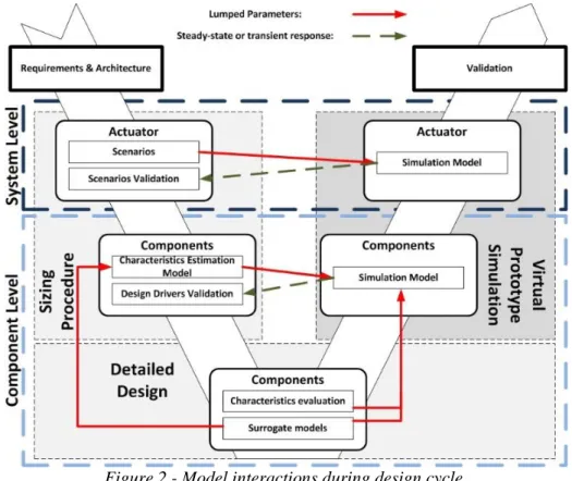
As shown in Figure 2, authors try through the framework to combine different levels of knowledge usually available at different design steps for preliminary sizing. For instance, a sizing procedure of an aircraft system is used to integrate component level models such as scaling laws and surrogate models from FEM simulations and system level models such as sizing scenarios and virtual prototype simulations. The association of models developed during these three stages offers the possibility to deliver a more accurate and more optimized system preliminary design.
Scott Delbecq, Florent Tajan, Marc Budinger, Jean-Charles Maré, Florian Sanchez
5
3 DYNAMIC MODEL
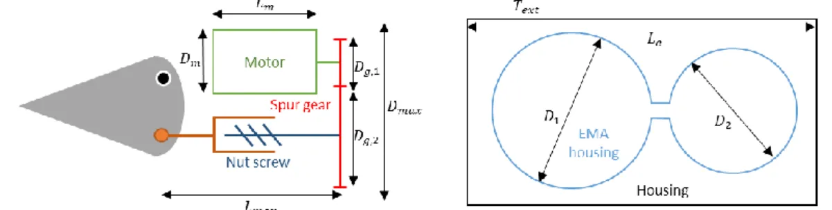
Usually in preliminary activities, only steady-state models are used to size a component. However, using more complex dynamic or non-linear models at this step of the design could be a good way to avoid loops between the preliminary design and the validation step. To illustrate this, it is proposed to apply the presented framework coupled with dynamic simulations on the preliminary design of a linear parallel axis geared drive EMA for aileron. This EMA is composed by an electric motor, a spur gear and a nut screw, and its housing has a two parallel cylinders shape. It is integrated in the aircraft wing, and is only cooled by natural convection in a confined space.
Figure 3 - Linear EMA geometrical environment
The idea here is to test the full EMA preliminary design on a typical flight profile (2 hours flight) and to see if its thermal behavior meets the EMA’s requirements. This part will first describe the used dynamic model and then explain how it is integrated in the preliminary design framework.
3.1 Modelling philosophy
In order to build a good model, an important step is to first define the “requirements” of this model, as it was a product. This will automatically focus the work on the required phenomenon to be modelled and how to model them. It is proposed to build the model on the following requirements inspired from [7]:
(R1) Realism: The model shall reproduce the key physical effects that impact the thermal behavior of the actuator. This need requires to build a model with a good representation of the thermal behavior of the EMA. To do so, modelling activity is driven using the results of finite elements simulations.
(R2) Minimalism: The model shall avoid considering unnecessary effects. This requirement implies two aspects: avoiding considering non-existent phenomena to solve numerical issues, and that there is no need to consider effects that are not influent on the analyzed behavior. For instance here, backlash in the mechanical transmission has a minor impact on the thermal behavior, and thus will not be considered.
(R3) Parameterization: The model shall use parameters that are easily found (e.g. datasheets) or possible to be calculated or extracted from the design or finite element simulations. The idea here is to avoid developing a complex model that sounds representative, but which uses parameters that are hard to estimate.
(R4) Simulation time optimization: As the model will be used during an optimization process to evaluate a long simulation, there is a strong requirement to minimalize the simulation time. This can be achieved by avoiding discontinuities, algebraic loops, or the representation of high dynamics.
3.2 Actuator model for thermal behavior
3.2.1 Interfaces
From the mission profile, the dynamic model will receive as inputs:
- The surface steering rate 𝜔𝑆 - The ambient temperature 𝜃𝑒𝑥𝑡
- The surface hinge moment 𝑇𝑆 - The aircraft altitude 𝑧 and will output for preliminary design purpose:
- The motor hot spot temperature 𝛳𝑚 - The housing temperature 𝛳ℎ𝑜 3.2.2 Considered phenomena
- Mechanical transmission parts
In order to meet R1 and R2, only the functional effects (transmission ratios) and the losses are considered. Those mechanical losses will also impact the thermal behavior as they produce heat flow. Considering R3, the losses will be calculated using the efficiency of the spur gear 𝜂𝑟𝑒𝑑, the direct and indirect efficiencies (𝜂𝑛𝑠,𝑑, 𝜂𝑛𝑠,𝑖) of the
nut screw, and its tare losses 𝐹𝑛𝑠,𝑡𝑟 (those can be easily found in datasheets for example). Then, the rotor speed 𝜔𝑟 and the rotor torque 𝑇𝑟 can be computed using the lever arm between the linear EMA and the surface hinge 𝑙𝑎, the pitch of the nut screw 𝑝𝑛𝑠 and the reducer ratio 𝑁𝑟𝑒𝑑.
- Motor losses model
To be representative of the motor thermal losses (R1 and R2) and to decrease the simulation time (R3), only the copper and iron losses of the motor are calculated. The rotor inertia and the motor inductance are neglected because they involve high dynamics that are not influent on the thermal dynamics, and slow down the simulation. Furthermore, in commercial aircraft, the low bandwidth of the position control loop generate small inertial torques. Therefore, the copper losses (joule effect) are calculated by assuming the brushless motor equivalent to a DC motor:
𝑃𝑗 = 𝑅𝑚𝑖𝑚2 = 𝑅 𝑚(𝐾𝑇𝑟
𝑚) 2
(1) where 𝐾𝑚 is the motor torque constant, and 𝑅𝑚 is the equivalent motor resistance due
to the resistivity of windings. As the thermal aspect is important (R1), this resistance is made dependent on the motor temperature with the following formula:
𝑅𝑚(𝑇) = 𝑅𝑚,@𝜃𝑟𝑒𝑓(1 + (𝜃𝑚− 𝜃𝑟𝑒𝑓)𝛼𝑐𝑜) (2) where 𝜃𝑟𝑒𝑓 is the reference temperature, 𝑅𝑚,@𝜃𝑟𝑒𝑓 is the equivalent resistance at 𝜃𝑟𝑒𝑓,
and 𝛼𝑐𝑜 the temperature coefficient on the copper resistivity. The iron losses are calculated as a function of the motor speed using [8]formula:
𝑃𝑖𝑟 = 𝐾𝑖𝑟𝜔𝑚1.5 (3)
where 𝐾𝑖𝑟 is estimated through surrogate models based on finite element simulations (R3). 𝐾𝑖𝑟 is calculated as a function of the motor design (number of magnets 𝑁𝑚𝑎𝑔,
motor length 𝑙𝑚 and diameter 𝐷𝑚). - Thermal model of the motor
It is a hard work to build a 1-D thermal model of an electrical motor which meets the both R1, R3 and R4 requirements. Complex resistance and capacitance networks as described in [9] are really difficult to parametrize and lead to really long simulations. A simpler model using two resistance-capacitance pairs (respectively for the copper
Scott Delbecq, Florent Tajan, Marc Budinger, Jean-Charles Maré, Florian Sanchez
7
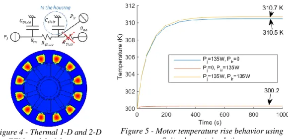
and the iron) is also often used (Figure 4). But an important approximation is made by neglecting the thermal resistance of the electrical insulation between the windings ant the iron of the motor. Therefore, to build a representative model (R1), finite element simulations has been made. Figure 5 represents the hottest spot of the motor (in the slot) as a function of the time, applying 135 W of copper losses in the slots and/or 135 W of iron losses in the iron while maintaining the skin temperature at 300K.
Figure 4 - Thermal 1-D and 2-D FEM model of the motor
Figure 5 - Motor temperature rise behavior using finite element simulation
This simulation shows that the iron has a negligible thermal resistance comparing to the copper (and insulation layer) one. Thus, the thermal capacitance of the iron will be include in the housing capacitance, and the thermal model of the motor will include the copper thermal capacitance and a global thermal resistance. The work achieved in [10] proposes an accurate way to estimate this thermal resistance based on the motor design using surrogate modeling. This resistance is calculated as a function of the motor diameter, its length and the insulate layer thickness.
- Thermal model of the housing
Regarding its slight impact on the hot spot temperature, the resistance/capacitance pair that could represent the air gap between the motor and the housing is neglected regarding R1 and R4. The housing resistance and capacity can be calculated using its dimensions. Since the iron thermal resistance is negligible the housing thermal capacitance will include the iron thermal capacitance. However, it is intended to consider the mechanical loss in our thermal model. As the housing is highly thermally conductive, a good approximation is to apply the mechanical losses directly on the housing capacity, and to consider a single thermal capacitance that merges the housing and the mechanical transmission thermal capacitances.
- Convection resistance
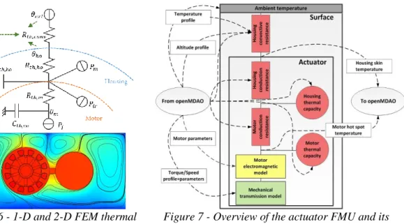
A methodology is proposed in [4] to evaluate the equivalent convection resistance between the housing and the external air to represent the heat transfer occurring in the EMA location. This resistance depends of each cylinder diameter (𝑑1, 𝑑2) and the length of the housing 𝐿𝑒 (see Figure 3). Based on finite element simulations, the influence of the aircraft altitude 𝑧 on the air properties is included, which affects the convection resistance.This leads to the global thermal network illustrated in Figure 6.
3.3 Co-simulation through FMI standard using PyFMI
The previously described model has to be integrated in the framework. This integration is done by converting the defined model (in the present case in DYMOLA) into a FMU (Functional Mock-up Unit). This generated model conforms to the FMI (Functional Mock-up Interface) standard that allows the exchange and the co-simulation of models created in different simulation environments. Here, the model has been generated through the co-simulation standard 1.0, described in Figure 7, which means that the DYMOLA solver (dassl in the present case) is integrated in the FMU. Then, pyFMI package [11] is used for modifying inputs and parameters, simulating the model and accessing the simulations results as it is required for implementing an optimization problem. The following figure shows the interaction between the optimization framework (based on the openMDAO framework [12]) and the 1-D model contained in the FMU.
Figure 6 - 1-D and 2-D FEM thermal model of the EMA
Figure 7 - Overview of the actuator FMU and its interfaces
4 ACTUATOR PRELIMINARY DESIGN AND RESULTS
4.1 Multidisciplinary Design Optimization (MDO)
The actuator design is done using a MDO approach. As seen previously, it involves several component models in the form of algebraic equations which come from analytical approaches, surrogate models [10] or scaling laws [3]. System-level knowledge determines the connections between component models and system-level models which evaluate system-level quantities such as geometrical integration parameters. The aggregation of these several models to formulate a global optimization problem, illustrated in Figure 8, is possible using openMDAO [12]. Furthermore, it is intended here to evaluate certain component design drivers - for instance the maximal motor hot spot temperature - and to validate certain system requirements - such as the maximal housing skin temperature - through a dynamic simulation of a civil aircraft mission. Thus, an additional system-level model is integrated in the optimization framework: the FMU, which represents the dynamic thermal behavior of the actuator in flight conditions described in part 3.
Scott Delbecq, Florent Tajan, Marc Budinger, Jean-Charles Maré, Florian Sanchez
9
Figure 8 - Actuator design optimization problem
MDO approach requires simulating the whole mission using the FMU at each iteration of the optimization process to find the optimal overall actuator mass. In order to reduce the number of iterations, gradient based optimizer (Scipy SLSPQ) and Design of Experiments driven multi-start were chosen. Gradients of algebraic models are obtained using symbolical computation where such computation is not possible for the FMU model. Thus, an approximate linear representation of the dynamic model is used to compute the FMU gradient. For instance, neglecting the thermal capacitances of the the equivalent housing skin temperature can be expressed as:
𝜃ℎ𝑜 = 𝜃𝑒𝑥𝑡 + (𝐾𝑖𝑟𝜔𝑚1.5+ 𝑅𝑚(𝐾𝑇𝑚 𝑚)
2
) ∙ (𝑅𝑡ℎ,𝑐𝑜𝑛𝑣+ 𝑅𝑡ℎ,ℎ𝑜) (4)
where 𝑇𝑚, 𝜔𝑚 are equivalent mean torque and speed at motor level according to the mission profile regarding respectively copper and iron losses of the motor. Additionally, the mission profile analysis gives the maximal values of torque and speed used in the actuator sizing procedure.
4.2 Results
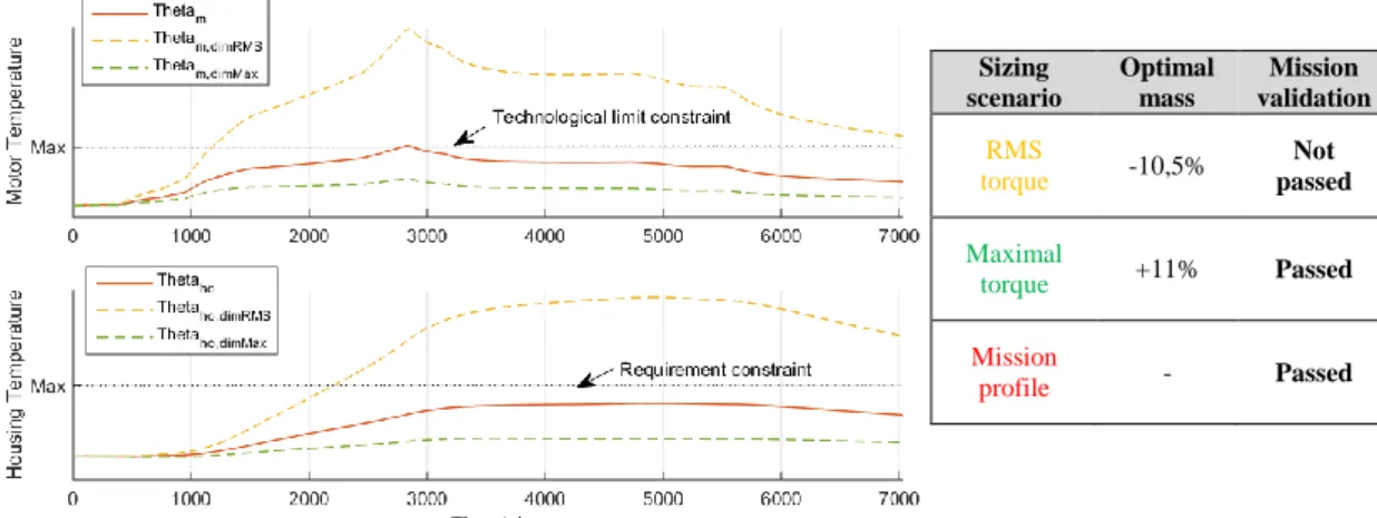
The previously described optimization problem has been solved considering that the thermal constraints are evaluated using the mission profile as a sizing scenario. This design is compared in Figure 9 with the result of two similar optimizations using respectively the Root Mean Square (RMS) torque and the maximal torque of the profile as sizing scenario (instead of the mission profile).
Sizing scenario Optimal mass Mission validation RMS torque -10,5% Not passed Maximal torque +11% Passed Mission profile - Passed
The Figure 9 shows the thermal response of each design to the mission profile and the values extracted for sizing. Those results show that considering the RMS torque as a sizing scenario is not sufficient to validate the preliminary sizing using the mission profile. On the other side, considering the maximal torque as the sizing criteria over-sizes the EMA. It can be seen on Figure 9 that the motor and housing temperatures always remain 50% lower than the limit defined by the technological and requirements constraints. Another interesting point is that the maximal temperature is achieved during the cruise phase. This is due to the low air density in high altitude that reduces the convective heat exchange between the actuator and the ambient air.
5 CONCLUSIONS
This paper presented a framework that allows designers to capture and (re-)use different types and levels of knowledge. A modelling approach of dynamic systems for optimization purposes has been described. Finally, an EMA has been preliminary sized and optimized using different types of models such as scaling laws, surrogate models and dynamic models. It has been shown how the proposed process enables the designers to assess the impact of the design drivers and the sizing scenarios on the sizing.
6 REFERENCES
[1] D. Arriola, A. Reysset, M. Budinger, F. Thielecke, and J.-C. Maré, “From Airframer
Requirements to Detailed Technical Specification of Electromechanical Actuators Aided by Knowledge-Based Methods,” in Proceedings of SAE 2013 AeroTech Congress & Exhibition, 2013.
[2] A. Reysset, M. Budinger, and J.-C. Maré, “Computer-aided definition of sizing procedures and
optimization problems of mechatronic systems,” Concurr. Eng., p. 1063293X15586063, 2015.
[3] M. Budinger, J. Liscouët, F. Hospital, and J.-C. Maré, “Estimation models for the preliminary
design of electromechanical actuators,” Proc. Inst. Mech. Eng. Part G J. Aerosp. Eng., vol. 226, pp. 243–259, 2012.
[4] F. Sanchez, M. Budinger, and I. Hazyuk, “Dimensional analysis and surrogate models for the
thermal modeling of Multiphysics systems,” Appl. Therm. Eng., no. August, 2016.
[5] M. Budinger, A. Reysset, T. El Halabi, C. Vasiliu, and J.-C. Maré, “Optimal preliminary design
of electromechanical actuators,” Proc. Inst. Mech. Eng. Part G J. Aerosp. Eng., vol. 33, no. 0, pp. 1–22, 2013.
[6] L. Allain, “Capitalisation et traitement des modèles pour la conception en génie électrique,”
Institut National Polytechnique de Grenoble, 2003.
[7] J. Maré, “Requirement-based system-level simulation of mechanical transmissions with special
consideration of friction , backlash and preload,” Simul. Model. Pract. Theory, Vol. 63, vol. 63, no. April 2016, pp. 58–82, 2016.
[8] J. Gieras, Permanent Magnet Motor Technology Design and Applications, Third edit. 2010.
[9] C. Sciascera, P. Giangrande, C. Brunson, M. Galea, and C. Gerada, “Optimal Design of an
Electro-Mechanical Actuator for Aerospace Application,” in 41st Annual Conference of the
IEEE Industrial Electronics Society, 2015.
[10] F. Sanchez and S. Delbecq, “Surrogate modeling technique for the conceptual and preliminary
design of embedded systems and components,” Congr. Int. Counc. Aeronaut. Sci., pp. 1–10, 2016.
[11] C. Andersson, “Methods and Tools for Co-Simulation of Dynamic Systems with the Functional
Mock-up Interface,” Lund University, 2016.
[12] J. Gray, K. Moore, and B. Naylor, “OpenMDAO: An Open Source Framework for
Multidisciplinary Analysis and Optimization,” 13th AIAA/ISSMO Multidiscip. Anal. Optim.