HAL Id: hal-02368268
https://hal.archives-ouvertes.fr/hal-02368268
Submitted on 18 Nov 2019
HAL is a multi-disciplinary open access
archive for the deposit and dissemination of
sci-entific research documents, whether they are
pub-lished or not. The documents may come from
teaching and research institutions in France or
abroad, or from public or private research centers.
L’archive ouverte pluridisciplinaire HAL, est
destinée au dépôt et à la diffusion de documents
scientifiques de niveau recherche, publiés ou non,
émanant des établissements d’enseignement et de
recherche français ou étrangers, des laboratoires
publics ou privés.
NS-2 model of homeplug AV PLC technology
Mortharia Meftah Bourahla, Laurent Toutain, David Ros Sanchez,
Abdesselem Kortebi
To cite this version:
Mortharia Meftah Bourahla, Laurent Toutain, David Ros Sanchez, Abdesselem Kortebi. NS-2 model
of homeplug AV PLC technology. SIMUTools 2011: 4th international conference on simulation tools
and techniques, Mar 2011, Barcelona, Spain. �hal-02368268�
NS-2 Model of HomePlug AV PLC Technology
Mortharia Meftah
!Laurent Toutain
!David Ros
!Abdesselem Kortebi
‡!Institut Télécom / Télécom Bretagne
Rue de la Châtaigneraie, CS 17607 35576 Cesson Sevigne cedex, France
{mortharia.meftah, laurent.toutain, david.ros}@telecom-bretagne.eu
‡France Télécom
2, avenue Pierre Marzin, 22300 Lannion, France
[email protected]
ABSTRACT
Power-Line Communication (PLC) technology has received considerable attention over the last few years because of its connectivity advantages and its transmission capacity. However, to the best of our knowledge, there is a lack of simulation tools to evaluate the performance of PLC-based networks. In this paper, we present a new PLC simulation model based on the HomePlug AV standard (HPAV) for the ns-2 simulator. This model allows the study of the pri-oritized HPAV CSMA-based MAC access service including PLC channel properties with OFDM and Tone Map aspects. In this access service, all of the Priority Resolution Period (PRP) and the processes of framing and segmentation are considered, and a new MAC queue system is developed to ensure HPAV flow classification. Besides, the model design enables the simulation of a hybrid In-Home or low voltage Access network with a mix of wired and wireless technolo-gies. The model functionalities and design are reported in this paper with a preliminary performance analysis.
Categories and Subject Descriptors
G.3 [Computing Methodologies]: Model Development, Model Validation and Analysis
General Terms
Design, Performance, Measurement
Keywords
Power Line Communication, PLC, HomePlug AV, simula-tion, In-Home Network, Access Network.
1.
INTRODUCTION
The use of the electrical power supply network for com-munication purposes has made Power-Line Comcom-munication
Permission to make digital or hard copies of all or part of this work for personal or classroom use is granted without fee provided that copies are not made or distributed for profit or commercial advantage and that copies bear this notice and the full citation on the first page. To copy otherwise, to republish, to post on servers or to redistribute to lists, requires prior specific permission and/or a fee.
SIMUTools 2011 March 21–25, Barcelona, Spain.
Copyright 2011 ICST, ISBN 978-1-936968-00-8.
(PLC) technology an interesting alterative and a comple-mentary solution to classical wired and wireless communi-cation systems. In fact, PLC technology brings about new advantages for the networks; it provides an easy and cost-effective network deployment and allows extending network coverage, since no extra wiring is required and the user just has to plug the PLC equipment into the outlets or the elec-trical units to access network services.
1.1 PLC technologies
With the large coverage of the electrical supply networks and their different voltage levels (low, medium and high voltage), several deployments of PLC technology can be achieved. So far PLC developments are mainly focused on technologies with low (LV) and medium voltage lines, which allow deployment of in-Home and outdoor PLC Access net-works as well as the distribution PLC network [9]. The high voltage lines, used to connect the power plant to the transport substations, are a very noisy environment to data transmission and such PLC deployment requires a high in-vestment to connect large scale networks [10].
Because of the importance of telecommunication access tech-nologies, current development of PLC is mostly directed to-ward broadband network solutions for In-Home and Access network applications based on LV line voltages. In-Home PLC uses the internal LV electrical infrastructure of houses or buildings as a transmission medium to build a PLC local network, in order to connect devices such as: IP phones, computers, video devices and so on, via a PLC modem, and allows multimedia and triple-play services as well as home automation services (e.g., automatic light control). The use of PLC technology in the Access networks provides an im-portant economical gain compared to an additional infras-tructure. Moreover, with hybrid deployment of these tech-nologies and other wired/wireless techtech-nologies, PLC might be easily integrated into the broadband market dominated by ADSL, cable and new wireless and fiber optic technolo-gies. However, to be as efficient as the other technologies, PLC technology needs to achieve a sufficient QoS through a high data rate on the medium.
1.2 PLC requirements and paper contribution
Nowadays, there are several PLC specifications (Home-Plug[7][6], HD-PLC [1] and so forth) and the IEEE 1901 standard for broadband over power-line networks [11] [3] has been recently released. Even though they have different
characteristics, these specifications share the main Physi-cal and Medium Access Control (MAC) layer functionali-ties. In the PLC physical layer, owing to the PLC electri-cal channel characteristics, e.g., frequency attenuation, elec-tromagnetic noise and perturbations, efficient modulation techniques, such as Orthogonal Frequency Division Mul-tiplexing (OFDM), and transmission strategies, e.g., For-ward Error Correction (FEC), Automatic Repeat reQuest (ARQ), should be used in order to improve transmission ca-pacity and the network connectivity and coverage. At the same time, to achieve the best possible performance and ensure the competitiveness with other access technologies, PLC MAC should provide good network utilization and QoS guarantees, considering the PLC channel specifics.
Several research works have dealt with modeling the elec-trical network and its numerous parameters (topology, wiring and devices, perturbations, and so forth), so as to study PLC channel behavior and define a suitable PLC channel adapta-tion mechanism (see, e.g., [17], [16] or [14]). However, nowa-days, the issue of PLC MAC layer is considered only in few research papers (e.g., [8], [13]) and not many tools are avail-able to model its functionalities (e.g., [15], [12]). The authors of [15] present a simulation model for a power line MAC pro-tocol based on a basic contention access without QoS ser-vice. Besides, this model is not compliant with the IEEE 1901 standard. In [12], the proposed PLC MAC simula-tion model for QoS support represents an OFDMA/TDMA scheme that applies Frequency Division Multiple Access in OFDM-based PLC transmission system. This access service uses a reservation access protocol to ensure QoS guarantees. However, only some manufacturers of the PLC equipement implement this scheme and to use this model in our work, it would be necessary to make important modifications.
Accordingly, we propose in this paper a PLC simulation model, for network simulator (NS-2)[5], to study PLC MAC performance with a generalized PLC channel model. This PLC model is based on HomePlug AV (HPAV) standard[7] because it is the de facto PLC standard, since most devices available on the market comply with HomePlug specifica-tions, a baseline standard for broadband access technology (BPL) and especially, a key element of the IEEE 1901 stan-dard.
The HPAV simulation model consists of three components: PHY, MAC and Network. The MAC accurately models the CSMA/CA contention access with Priority Resolution Pe-riod. The model extension for supporting the TDMA con-tention free access technique is under development. More-over, in this component, the HPAV flow classification and framing schemes are also designed to investigate behavior of the segmentation process in this system. For this purpose, a new queue system is developed. In the PHY component, we consider a generalized channel model of the low volt-age electrical supply network, in order to be used as shared transmission medium for In-Home or BPL Access networks. HPAV PLC network topology and channel characteristics, such as OFDM modulation and Tone Map scheme, are es-tablished via the Network component to assess the impact of such parameters. Moreover, the model design makes pos-sible a hybrid deployment of HPAV PLC with available ns-2 wired and wireless technologies.
The rest of this paper is organized as follows. Section 2 re-views the main HPAV PLC technology features, especially
Ethernet II
Class stack Other
ETH SAP Other
Classier and other CL functions
CL CL-MAC SAP MAC MAC-PHY SAP PHY Control SAP CM CCo
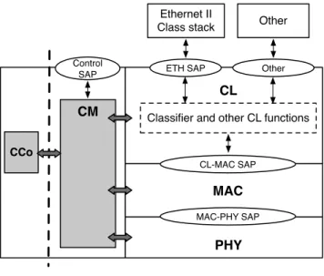
Figure 1: HPAV access system
those implemented in the model. In section 3, we describe the design and implementation of the HPAV PLC model and its relationship with ns-2 existing modules. Afterwards, the HPAV model validation is discussed in section 4 and, in sec-tion 5, we present the performance evaluasec-tion of HPAV PLC technology in various scenarios and we analyze the behavior of its different features. Finally, the last section concludes this paper and outlines some ideas for future work.
2. HPAV PLC STANDARD
Created by the HomePlug Industrial Alliance[2], Home-Plug solutions, and in particular HPAV allow high speed and good quality power-line home networking. HPAV was designed to support the emerging voice, video and multime-dia applications with transmission rates up to 200 Mbits/s (physical capacity). Figure 1 shows the HPAV access sys-tem. The Convergence Layer (CL) and MAC constitute the access data plane of the HPAV protocol stack, while the Con-nection Manager (CM) and the Central Coordinator (CCo) protocol entities define the control plane. In this section, we focus on the main HPAV system functionalities and network concepts developed in our model (see [7][6] for more details).
2.1 HPAV network
PLC technology is adapted to the specific network topol-ogy of the electrical channel and to its physical characteris-tics. Accordingly, the LV PLC network has generally a tree topology; it consists of several branches, i.e., network sec-tions where each section connects a variable number of PLC nodes (i.e., simple devices in an In-Home network, or user networks for an Access network).
Moreover, the communication between PLC nodes depends on the electrical channel capacity to transport data signals because electrical wiring was not originally designed for data transmission. In fact, the variety of devices that could be connected to this wiring impacts PLC channel properties (e.g., impedance) and introduces different forms of noise and perturbations. Moreover, like radio signals, attenuation of the electrical signal is a function of the distance traveled by the signal. Consequently, all these elements determine
Beacon CSMA Region
Beacon
PRS0 PRS0 PPDU SACK PRS0 PRS0 PPDU SACK PPDU SACK PPDU SACK PPDU SACK
Reserved Region Beacon Period CF Alloc #1 CF Alloc #2 B2BIFS RIFS CIFS AIFS RIFS_AV CFIFS RIFS_AV AIFS RIFS_AV B2BIFS PRP Contention Beacon
Figure 2: HPAV Beacon period access structure
the physical network of each PLC node, i.e., the set of PLC nodes that can receive the PLC signal and physically com-municate with with a given PLC node.
In addition, HPAV technology defines the logical network concept, AVLN (AV Logical Network), to structure and en-hance network communication. Thus, a PLC network is considered as a logical bus network connecting a number of PLC nodes that apply the same communication and secu-rity strategies, while considering the distance and channel characteristics between these nodes. In each AVLN, one PLC node, called the CCo, is responsible for defining these strategies, in order to set up and maintain the AVLN, man-age the communication resource on the wire, and ensure coordination with neighbor networks that use the same wire resource.
2.2 Channel adaptation
To transmit data over electrical wiring, the line frequency of electrical circuit is supplemented by a modulated signal, at a frequency determined by the PLC technology; i.e. 2 - 28 MHz for HPAV. Therefore, to overcome PLC channel char-acteristics, OFDM has been chosen as the HPAV modulation technique because of its good performance, as observed in wireless technologies (e.g., IEEE 802.11). In HPAV, the 917 carriers used for modulation may be coherently modulated with Binary Phase Shift Keying (BPSK), Quadrature Phase Shift Keying (QPSK), 8-Quadrature Amplitude Modulation (QAM), 16-QAM, 64-QAM, 256-QAM, or 1024-QAM mod-ulation, depending on channel conditions.
Moreover, to provide optimal performance, HPAV deploys a channel estimation process to optimally adapt the PHY features to the time varying character of the PLC chan-nel, which also differs between each two PLC nodes. This process is invoked by a PLC node either when it does not have any information on channel status to transmit data, or when it detects a change on channel characteristics based on received packets. It consists of selecting the appropriate Tone Map, i.e., determining a set of modulation methods for each carrier, the guard interval for OFDM symbols, and the FEC rate, in order to improve PLC transmission quality. The Tone Map coding schemes are not defined in the HPAV specification and are implementation-dependent.
2.3 HPAV MAC protocols
Primarily, access in HPAV is periodically structured along a beacon period as depicted in Figure 2. To improve access stability, the beacon period is synchronized with the 50 (or 60) Hz AC line cycle with a duration of twice that of the AC line cycle period [7]. This period consists of a beacon
pe-riod for transmission of Beacon frames and pepe-riods for data transmissions of AVLNs PLC nodes sharing the medium. In the beacon period, the channel access information is commu-nicated by the CCo, via a Beacon frame, so as to set up the access schedule and provide synchronization for the AVLN PLC nodes. For data transmissions, two access services are deployed in the MAC layer: a contention-based access ser-vice using CSMA/CA protocol, as there is no guarantee of collision detection in the PLC channel, and a contention free service with TDMA. The CL identifies, by means of the flow classification process, the required service for the transmis-sion: prioritized or parameterized QoS access. Then, based on bandwidth availability, the CCo determines when PLC nodes may use CSMA/CA access or be assigned exclusive access through TDMA.
2.3.1 CSMA/CA access
The HPAV contention-based access service involves two access control periods. First the Priority Resolution Period (PRP) then followed by a contention period. The PRP con-sists of two Priority Resolution Slots (i.e., PRS0 and PRS1) [6] through which the HPAV MAC establishes a differen-tiated access service with four Channel Access Priorities (CAP), CAx, x =0, 1, 2, and 3. The four priority levels are assigned by the CL by mapping the eight 802.1Q user priorities onto four access priorities, so that CA3 is the high-est priority and CA0 is the lowhigh-est. Each PLC node asserts its higher CAP in the PRS slots; it sends or does not send the priority signals in the PRS0 and PRS1 intervals
accord-ing to its CAP. PLC nodes with CAPx = 0b(b1b2) send
a signal in PRS0 or PRS1 only if b1 or b2 is 0b1,
respec-tively. Otherwise, if b1 or b2 is 0b0, PLC nodes just sense
the medium to determine the existence of higher priority PLC nodes and thus stop sending a signal. At the end of the PRP, only the nodes with higher CAP are authorized to contend for the medium in the contention period, causing the other nodes to defer to the next PRP. Nevertheless, if for this highest CAP, there are multiple flows in the same PLC node, the contention-based access system should select one flow for the contention period. In HPAV, no access strategy is specified, so we define two strategies based on First In First Out (FIFO) and Round Robin (RR) queue processing techniques.
In the contention period, PLC nodes with higher CAP per-form the HomePlug backoff algorithm that determines a ran-dom time to wait before deciding to transmit [6]. Three counters are used in this backoff algorithm, backoff counter (BC), backoff procedure event counter (BPC) and deferral counter (DC). BC is the number of contention slots to wait,
Table 1: CW and DC as a function of the BPC and CAP [6]
CAP3 and CAP2 CAP1 and CAP0
BPC = 0 CW = 7, DC = 0 CW = 7, DC = 0
BPC = 1 CW = 15, DC = 1 CW = 15, DC = 1
BPC = 2 CW = 15, DC = 3 CW = 31, DC = 3
BPC > 2 CW = 31, DC = 15 CW = 63, DC = 15
and it is set to any random value in [0, WC ], where WC denotes the contention window size defined according to the transmission CAP and the number of transmission BPC (Ta-ble 1). If the medium remains idle for a slot time, the PLC nodes decrement their BC and keep decrementing until it reaches 0 and the transmission occurs. Nevertheless, if the medium becomes busy, the nodes must pause their BC and wait for the next transmission attempt. Once transmitting is completed, the transmitter waits for a selective acknowledg-ment (SACK) from the receiver, after a defined interframe space (IFS). However, when a collision occurs, either if the SACK frame is not received, or when the SACK is received with information indicating data reception with errors, the transmitter also attempts to retransmit.
For each retransmission attempt, the backoff procedure uses the deferral counter mechanism to improve collision avoid-ance. The key idea of this mechanism is to prevent collision when the collision probability is high based on the number of times the backoff procedure is called. Depending on the DC counter value, which is also set according to the transmis-sion CAP and BPC, BC should be reinitiated, if DC reaches 0, using the incremented value of BPC, or otherwise it is resumed and DC decremented. Therefore, BPC is used to increase CW and thus decrease collision probability.
2.3.2 TDMA access
To provide a deterministic service, HPAV enables resource allocation by using a TDMA-based channel access. In this service, resource allocation is initiated when a higher Layer protocol of a PLC node requests transmission with its asso-ciated CSPEC (i.e., Connection Specification) information about the required QoS.
Based on the CSPEC, the connection manager CM in the PLC node determines the need of resource allocation and communicates with the CM of the destination station to es-tablish the connection. Once the connection is eses-tablished, the CM communicates the CSPEC and the connection infor-mation, such as the Tone Map used, to the CCo to establish the required allocations in the reserved region of a beacon period. For this purpose, an admission control procedure is performed by the CCo to determine whether there is ade-quate bandwidth available to support the request, without compromising the QoS of existing connections. Moreover, the CCo uses a scheduling procedure to provide the appro-priate allocation schedule within a beacon period by consid-ering a Minimum CSMA region for CSMA access service and the QoS allocations in reserved region. Additional CSMA Regions may also be present in the Beacon Period depending on resource availability.
2.3.3 Framing and Segmentation processes
To reduce the overhead due to retransmissions, the data to be transmited is segmented into fixed size segments and
Frame Header
ATS
Optional MSDU Payload ICV
MAC Frame
MAC Frame #i-1 MAC Frame #i MAC Frame #j-1 MAC Frame #j
Segment 1 Segment n Pad PBH PBB#1 PBC ... PBH PBB#n PBC 2 octets MAXFL_AV 2 octets Encryption Encryption PB#1 PB#n MAC Frame stream MPDU Payload AV Preamble FC Symbol
(SOF) MPDU Payload
AV Preamble FC Symbol (SOF) AV Delimiter SACK 4 octets CIFS RIFS_AV
Figure 3: The framing and segmentation processes
each segment is transported separately on the PLC chan-nel. Since PHY errors occur on a segment, segmentation ensures that only corrupt data is retransmitted. For seg-mentation purposes, the HPAV access system conducts the framing process.
When the CL receives an MSDU from higher layer protocols, e.g., an Ethernet frame from the Ethernet Service Access Point (SAP), the MSDU is adapted according to the SAP by the Protocol Adaptation Layer (PAL), then the MAC fram-ing process generates the MAC data frame. The MAC data frame is composed of a MAC frame Header, and optional Ar-rival Time Stamp (ATS) and Integrity Check Value (ICV). The MAC data frame header carries information about the presence of ATS and the length of the MAC frame. ATS indicates the time when the MSDU arrived at the CL; it is used as a part of a jitter control mechanism deployed to ensure QoS[7].
The CL provides the MAC data frame to the HPAV MAC with a Link identifier (LID) that identifies the service at-tributed to the MSDU, i.e., four Priority LID for the differ-entiated service and a Global LID used as a unique identifier for each connection with TDMA access in an AVLN. Based on the LID, the HPAV MAC continues the framing process and classifies MAC data frames for differentiated or
param-eterized service using the{DTEI, PLID, CLST} or {STEI,
GLID} information, respectively. DTEI and STEI are the
source and the destination address of the MSDU, and the CLST identifies the CL SAP. Hence, the MAC data frames sharing the same information are concatenated to form data streams. Each data stream is then segmented into 512-octet segments for transportation as part of an MPDU payload. At physical layer, each segment is encapsulated onto a single FEC Block (PB) of a PPDU by adding a PHY Block Header (PBH) and PHY Block Check Sequence (PBCS). The PBH and the Frame Control (FC) information uniquely identify the data stream to which a segment belongs and, thus, allows the reassembly process of MAC data frames. The number of PB transmitted in the MPDU depends on the channel transmission capacity and is limited by the maximum frame length MaxFL AV. Figure 3 shows a framing and segmen-tation processes example.
HP4 HP2 HP1 HP3 CCo Tranformer/ Meter unit PLN HP4 HP1 HP2 HP3 CCo PLC channel Vlink AVLN
Figure 4: HPAV Network design
In HPAV, MAC framing and segmentation are defined as processes that ensure a maximum size MPDU exchange over the medium, and thus improve efficiency of the HPAV ac-cess protocol. Accordingly, we present in this paper some preliminary performance results of the HPAV system with and without these processes.
3.
THE NS-2 HPAV PLC MODEL
The Network Simulator ns-2 is a powerful simulation tool that is widely used for wired and wireless data networking research. Currently, this simulator does not provide a pub-lic implementation of PLC technology. In particular, to the best of our knowledge, there is no simulation model for the HPAV PLC QoS solution. Therefore, we have implemented our HPAV PLC simulation model in accordance with the HPAV specification and based on the ns-2 version 2.30. In this model, we investigate the HPAV CSMA-only mode that deploys CSMA/CA access service throughout the bea-con period, without beabea-con and reserved region. The TDMA access service is not yet available in our model, but we are currently working on implementing it in the simulator.
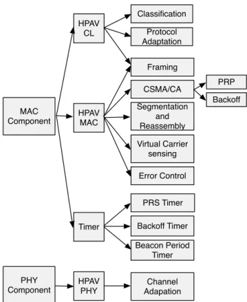
Basically, in ns-2, for each new transmission technology, we have to specify the technology architecture by defin-ing the network topology, the transmission channel and the nodes structure; then, we design the technology functional-ities. Our developed simulation model is realized through three components: Network, MAC and PHY. The Network component provides the HPAV network architecture and de-fines the PLC network topology and node structure using the OTcl language. This component allows establishing the interconnection of the PLC nodes along the shared PLC channel with specific transmission properties. On the other hand, the MAC and PHY components, which represent the HPAV access system modules, model the main HPAV func-tionalities of any PLC node (see Figure 6). Both components are implemented using C++.
In this section, we present the design and implementation details of both the network architecture and the functional blocks for the HPAV simulation model.
3.1 HPAV Network Architecture
In our HPAV model, we suppose that all the PLC nodes of an HPAV network share the same physical network and belong to the same AVLN. The CCo node is selected when configuring the HPAV network.
The PLC network presents some similarities with a wired LAN network and wireless technologies such as 802.11. In fact, despite a tree topology, PLC uses a shared transmission
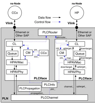
CCo HP CL Queue HPAVMac HPAVPhy CM CCo PLCInfo PLCChannel Vlink PLCIface PLN ns-Node Ethernet or Other SAP CL Queue HPAVMac HPAVPhy CM PLCIface ns-Node Vlink PLCRouter Control ow Data ow uptarget_ channel_ downtarget_ downtarget_ uptarget_ uptarget_ downtarget_ plci_ Ethernet or Other SAP cl_ mac_ cm_ plcrouter_ cco_ cm_ cm_ PLCPropagation propagation_
Figure 5: HPAV Network Architecture
medium, and presents, as wireless networks, a noisy channel with time varying transmission characteristics between the PLC communication nodes. Therefore, the network archi-tecture of the HPAV model is mainly based on that of the ns-2 LAN model.
To model the shared transmission medium, a new type of ns Node object, called PLN is created to keep together all the shared objects on the PLC network: the PLC chan-nel PLCChanchan-nel, the routing object PLCRouter, the general network characteristics object PLCInfo and the PLC prop-agation model PLCPropprop-agation. The PLCChannel models the shared medium with support for contention mechanisms, e.g. carrier sense and contention. For routing purposes, there is just one routing object for all PLC network nodes that is able to determine the next hop for the packets sent on the PLC network in the context of the simulated network. The PLCInfo object is like the GOD object in a wireless network, as it stores the PLC channel characteristics, e.g., number of PLC network nodes, the distance and error rate variation between these nodes, the Tone Map used, a de-fault propagation delay, etc. To compute the propagation delays between the PLC nodes, the PLCChannel can use the PLCInfo default propagation delay, or refer to a propa-gation model PLCPropapropa-gation. The PLCPropapropa-gation is an abstract model that uses the information provided in PL-CInfo, as the distance between the PLC nodes, to determine the propagation delays. It only serves as a placeholder for possible future extensions.
In addition, as shown in Figure 4, the PLN connects the set of PLC nodes using a virtual link Vlink ns object, so that each unidirectional electrical link between two PLC nodes is modeled by a Vlink between the first PLC node and the PLN and a Vlink between PLN and the second PLC node. This link type does not impose any delay on the packet and only serves to install a shared medium. Thus, each com-munication in the PLC network is relayed through the PLN
MAC Component PHY Component HPAV MAC HPAV CL HPAV PHY CSMA/CA Framing Segmentation and Reassembly Channel Adapation Virtual Carrier sensing
Timer Backoff Timer Beacon Period Timer PRS Timer PRP Backoff Error Control Protocol Adaptation Classication
Figure 6: HPAV Access system modules in CSMA-only mode
respecting a 1/2 routing cost for each Vlink.
In this model, we provide the possibility of deploying hy-brid network topologies including HPAV, wired and wireless links. For that end, the HPAV PLC nodes are modeled us-ing the basic ns-2 Node object and a new interface object PLCIface that represents the HPAV access system. This PLCIface object is placed in PLN shared object to enable the use of different ns Node derived objects like the wire-less ns-2 Node; each PLC node can act as a gateway for the wired and wireless domains. Figure 5 illustrates the HPAV network architecture with the structure of the HPAV nodes, CCo or simple node (HP), as designed in the HPAV model. The description of the PLCIface objects and their function-nality are dealt with in the next section.
3.2 HPAV model features
As mentioned above, the HPAV Access system features are modeled by the MAC and the PHY components of the HPAV simulation model. These two components are made by the PLCIface objects depicted in Figure 5. The functionalities developed to ensure the HPAV CSMA-only access mode are presented in Figure 6, which graphically shows the module hierarchy of the MAC and PHY components. The detail components are described as follows.
3.2.1 MAC and PHY Components
The MAC component comprises the Convergence Layer CL, the Queue, the HPAVMAC and the HPAVPHY objects. The CM and the CCo objects are not used in the HPAV
CSMA-only access mode. The PHY component handles
the Channel Adapatation process which adapts the physical characteristics of the transmission for the MAC component. 1) CL: The CL module, which is derived from the ns-2 LinkDelay Class, performs the protocol adaptation layer (PAL) and the classification processes of the HPAV Con-vergence Layer on the received MSDUs. The SAP of the higher layer is configured for each PLC node via the OTcl simulation script. The access priority for the flow MSDUs corresponds to the priority parameter (prio ) of the ns-2 Agent object. Two CLSTs are supported by our model: IEEE 802.3 Ethernet with or without IEEE 802.2 (LLC) and IEEE 802.11.
The CL provides the received MSDU to the HPAVMAC module with the required information, as the CAP, CLST, and the STEI and DTEI of the MSDU, in order to construct the MAC data frame. To determine the DTEI, the CL uses the PLCRouter module services to identify the next hop for the MSDU IP destination address (i.e. the ns-2 address of the transmitting Agent) in the AVLN network. Based on this information, the MSDU is relayed to the Queue.
2) HPAV Queue: In the Queue module, we define two queue system types to manage the MSDUs in accor-dance with the CL provided information. A DropTail queue HPAVQ is assigned for each flow requiring TDMA access. The access scheduling for these flows is defined by the CCo admission control procedure. For the prioritized access pack-ets, a Priority queue system PrioQ is defined to manage packets with the same CAP, and possible different DTEI, CLST and ns flow identifier. Access between the different flows in thePrioQ is carried out according to FIFO or RR queue processing techniques. In the first case, all packets are enqueued in the same queue, and the packet at the head of the queue determines the flow for the next HPAVMAC access. For the HPAVMAC, the segmentation process is ap-plied to the packets of the flow that has gained access. In the RR access technique, each flow in thePrioQ is managed separately in a Drop Tail queue and the access is achieved one by one in a round robin manner. The performance of these techniques is discussed in section 5.
3) HPAVMAC : This module extends the ns-2 MAC class, which is used to simulate the medium access protocols of a shared medium[5]. To establish the HPAV CSMA-only access mode, the HPAVMAC involves the priority resolution process and the contention procedure. Priority resolution is executed regardless of whether an MSDU is queued for transmission, in order to maintain knowledge of the highest priority contending for the channel. The HPAVMAC starts the PRP by asserting its highest priority CAP in the shared PLCChannel for the PRP duration. At the end of the PRP, all the PLC nodes retrieve the PLCChannel access prior-ity. The PLC nodes with the PLCChannel access priority start the contention procedure, and the other nodes follow the Virtual Carrier Sense procedure and defer to the next PRP. In the contention Period, the HPAVMAC invokes the HomePlug backoff procedure as described in section 2.3.1 and defines its parameters BC, BPC and DC according to Table 1.
Once the node acquires access to the PLC channel, it performs the Segmentation procedure and constructs the MPDU as depicted in Figure 3. The ns-2 Packet, which
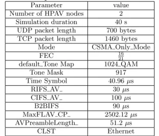
Table 2: Main parameters of the simulated model
Parameter value
Number of HPAV nodes 2
Simulation duration 40 s
UDP packet length 700 bytes
TCP packet length 1460 bytes
Mode CSMA Only Mode
FEC 1621
default Tone Map 1024 QAM
Tone Mask 917 Time Symbol 40.96 µs RIFS AV 30 µs CIFS AV 100 µs B2BIFS 90 µs MaxFLAV CP 2502.12 µs AVPreambleLength 51.2 µs CLST Ethernet
transports the MAC data frame, may be divided into one or more parts to form a segment, or concatenated with other ns-2 Packet to fit in a single segment. Each ns-2 packet is identified by the higher layers by means of its ns-2 address, protocol, event id and other information. To that purpose, the ns-2 Packet header of a MAC data frame is stored in order to reassemble the MAC data frame by the receiver node.
The maximum FL AV used to limit PLC node access in HPAV can be configured in the OTcl simulation script. This parameter and the PLCChannel characteristics, such as Tone Map and FEC, between the transmitter and the receiver de-termine the number of segments to transmit. The MAXFL AV can be used to perform the Deficit Round Robin DRR or other derived scheduler mechanisms for CSMA/CA access. Once the PPDU is transmitted, collision is inferred in the following circumstances:
• if the receiver receives a frame other than SACK, which occurs if the PLC nodes are not synchronized with respect to the state of the PLCChannel,
• if two frames are received at approximately the same time by the transmitter or the receiver node,
• if the packet is received with errors.
In this case, transmission is deferred until the end of the current transmission by using Virtual Carrier Sense proce-dure.
A Timer object inherits the ns-2 Handler class to allow the HPAV event sequencing of the PRP period via the PRPti-mer, the contention period with the backoff timer and the different HPAV IFS, the Virtual Carrier Sense procedure to defer access and for the Beacon period structure and syn-chronisation.
4) HPAVPHY : In the HPAV PLC model, the HPAVPHY manages the main PLC physical features like computation of the probagation delay, estimation of the PLC channel characteristics and channel adaptation. The HPAV channel estimation consists to exchange a number of probe pack-ets, designated by Sound packets in HPAV, to define the apropriate Tone Map for the communication. In the HPAV
Number of HPAV nodes
Throughput (Mbps)
HPAV Simulation Model Real HPAV System
7 1 3 4 6 0 10 30 60 70 20 40 50 2 5
Figure 7: Comparison of the average HPAV
throughput of our HPAV model and real HPAV sys-tem
model, channel estimation can be controlled by limiting the maximum number of Sound packets exchanged or defining a maximum channel estimation period. The time varying characteristics of the PLCChannel, as the error rate, is a con-figurable parameter of the simulated HPAV network. There-fore, error control is applied to detect changes on the PLC-Channel and then, the PLC node starts to use the PLC-Channel Adaptation on the HPAVPHY layer.
4. HPAV MODEL VALIDATION
The HPAV model is designed to accurately reproduce the behavior of a HPAV system. However, as with every sim-ulation model, the validation process is of primary impor-tance. In our case, this process can be performed by com-paring simulation results obtained with the HPAV model to performance obtained from real HPAV system. There-fore, we have used the LEA[4] HomePlug AV adapters to test our model. The configuration of these equipments is based on default parameters specification of the HPAV. The test scenario consists to compare the average HPAV service throughput in saturated network, depend on the number of HPAV nodes deployed on this network. For this purposes, we have used UDP-based CBR flows with packet size of 700 bytes and disable the segmentation process on the model. The main parameters are given in Table 2 and the default RIFS value is 140 µs.
Figure 7 shows the average service throughput obtained from both the HPAV simulation model and the real testbed. All results generated by our HPAV simulation model shows a rather good match with those obtained with real testbed. Nevertheless, other verifications should be done by compar-ing for example the access delay to assess the CSMA/CA access service.
Simulation time (sec)
Throughput (Mbps)
TCP & Segmentation UDP & Segmentation TCP UDP 40 0 10 20 30 0 20 40 60 80
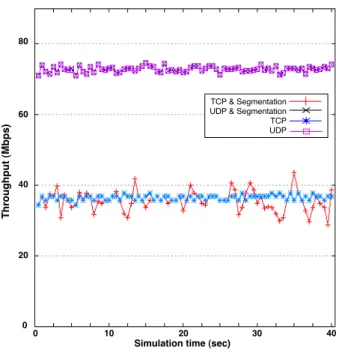
Figure 8: HPAV channel throughput
5.
PERFORMANCE EVALUATION
In this section we present a performance evaluation of the HPAV access system. The main parameters of the simula-tion model are represented in Table 2. The HPAV simulated network comprises two HPAV nodes relayed via the Ethernet SAP to the HPAV channel. Propagation delay is computed by using the distance between the two nodes.
Three scenarios are considered in this HPAV network where we focus on the HPAV access system performance with-out considering the time varying characteristics of the PLC channel. The HPAV channel Tone Map is fixed to 1024 QAM modulation over the 917 OFDM carriers.
- Scenario 1 : In this scenario, the throughput of the HPAV channel for UDP and TCP traffic is measured de-pending on whether the access system deploys the segmen-tation process or simply sends the flow packets as they are received. To this end, we overload the network with UDP-based CBR or TCP-UDP-based long-lived flows. Both flow types use the CAP3 and a packet size of 700 bytes for UDP and 1460 bytes for TCP. According to this configuration, the av-erage throughput achieved by the UDP and TCP traffic is 72 Mbps and 38 Mbps respectively, as depicted in Figure 8. Moreover, we observe in this scenario that the use of the segmentation process impacts the TCP traffic throughput; the curve of TCP throughput oscillates compared to that obtained without the segmentation process. This behavior occurs due to the delay that the receiver or the transmitter causes before receiving the complete packet; which probably impacts the congestion window. Consequently, we limit our study in this paper only to the UDP traffic. Nevertheless, a complete study of the impact of the segmentation on the TCP traffic is out of the scope of this paper.
- Scenario 2 : In order to further assess the CSMA/CA access mode with the PRP and the specific HPAV backoff
A
verage CAP
throughput (Mpbs)
Frame Length FL_AV (µs)
UDP_CAP3 UDP_CAP2 UDP_CAP1 UDP_CAP0
Figure 9: Achieved throughput of the HPAV differ-entiated service
of the contention phase, we compare the service provided to the four priority CAP in the HPAV access system. Thus, a set of UDP flows asserts access in each access priority, 7 flows UDP CAP3, 2 flows UDP CAP2, 1 flow UDP CAP1 and 1 flow UDP CAP0, of the same PLC node. Each UDP flow corresponds to 8 Mbps CBR traffic. The differentiated service is studied when varying the access length FL AV parameter, which determines the number of segments in the HPAV MPDU. The average throughput achieved by the four CAP services is shown in Figure 9.
As a result, we can see that the higher priority CAP3 oc-cupies the total bandwidth of the HPAV network. When we overload the network with flows UDP CAP3, the dif-ferentiated service over the four CAP gives absolute access to the higher priorities. This performance can be adjusted to provide a proportionally fair service between these access priorities. By increasing the frame length FL AV, the HPAV access service leads to more starvation for the lower priori-ties, while decreasing this parameter reduces this effect.
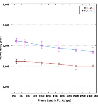
- Scenario 3 : In this scenario we investigate the im-pact of the scheduling mechanisms, i.e., FIFO and RR, on the HPAV access system performance, and especially with the segmentation process. The scheduler mechanism is de-ployed for the flows with same access priority. Therefore, a set of UDP flows (10 flows) with the same access prior-ity CAP3 is transmitted in the HPAV network. The same UDP flow characteristics, i.e., CBR traffic of 10 Mbps, are used to study the access system behavior when deploying the two scheduler mechanisms with different FL AV access lengths. The delay variation of these mechanisms is given in Figure 10. The results of this scenario assert that the HPAV access service can be improved by using efficient mechanisms to share channel access. The proposed scheduler mechanism based on an RR scheme improves the HPAV access service
Frame Length FL_AV (µs)
RR FIFO
Flows delay (sec)
Figure 10: Average delay resulting from deploying FIFO and RR scheduler mechanisms
for the flows within the same priority. As shown in Figure 10, the RR scheduler reduces the delay of the prioritized flows compared to that with the FIFO service. The RR scheduler provides a fair service regardless to the FL AV value. The possibility to define an appropriate FL AV value in function of the served flow allows to deploy a scheduler mechanism as a Smooth Round Robin SRR, the weighted Round Robin and other derived RR mechanisms that provide efficient re-source sharing.
6.
CONCLUSION AND FUTURE WORK
This paper presents a detailed design and implementation of a HPAV simulation model for ns-2. The designed model is based on the HomePlug AV standard and the ns-2 version 2.30. In this model, we have implemented the prioritized HPAV CSMA-based MAC access service with the priority resolution period and the framing and segmentation process. The PLC HPAV channel properties are modeled in order to study their time varying characteristics. A new MAC queue system is developed to ensure the HPAV flow classification and to schedule flow access according to the Round Robin scheme. We show through simulations that the simulated model, which reproduces the performance observed in the HomePlug equipments, requires deployment of an efficient scheduler mechanism for the CSMA access. Moreover, the investigation of the segmentation process leads to conclu-sions about the impact of this process on TCP performance. A direction for future work is the study of TCP performance in the HPAV PLC technology and the improvement of the HPAV CSMA access as well as finalizing the TDMA access development.
7.
REFERENCES
[1] HD-PLC Alliance. www.hd-plc.org.
[2] Homeplug Powerline Alliance. www.homeplug.org.
[3] IEEE P1901 working group.
http://grouper.ieee.org/groups/1901/. [4] LEA. http://www.leacom.fr/.
[5] NS-2. www.isi.edu/nsnam/ns.
[6] Homeplug 1.0.1 specification. HomePlug Alliance, December 2001.
[7] Homeplug AV specification, version 1.1. HomePlug Alliance, May 2007.
[8] A. Brkanic, M. Hadzialic, and D. Borovina. Effects of choice of MAC protocol on QoS parameters in BPL network. In ELMAR, 2008. 50th International Symposium, volume 1, pages 285 –288, September 2008.
[9] X. Carcelle. Power Line Communication in Practice. Artech House, 2009.
[10] D. Fink and R. J. Jeung. Feasible connectivity solutions of PLC for rural and remote areas. In Power Line Communications and Its Applications, 2008. ISPLC 2008. IEEE International Symposium on, pages 158 –163, April 2008.
[11] S. Goldfisher and S. Tanabe. IEEE 1901 access system: An overview of its uniqueness and motivation. Communications Magazine, IEEE, 48(10):150 –157, October 2010.
[12] H. Hrasnica and A. Haidine. Modeling MAC layer for powerline communications networks. In Internet, Performance and Control of Network System, Part of SPIE’s Symposium on Information Technologies, pages 5–8, 2000.
[13] S. Katar, L. Yonge, R. Newman, and H. Latchman. Efficient framing and ARQ for high-speed PLC systems. In Power Line Communications and Its Applications, 2005 International Symposium on, pages 27 – 31, April 2005.
[14] K.-H. Kim, H.-B. Lee, Y.-H. Lee, and S.-C. Kim. PHY abstraction methodology for the performance
evaluation of PLC channels. In Power Line
Communications and Its Applications (ISPLC), 2010 IEEE International Symposium on, pages 28 –32, March 2010.
[15] M.-S. Kim, D.-M. Son, Y.-B. Ko, and Y.-H. Kim. A simulation study of the PLC-MAC performance using network simulator-2. In Power Line Communications and Its Applications, 2008. ISPLC 2008. IEEE International Symposium on, pages 99 –104, 2008. [16] M. Tlich, A. Zeddam, F. Moulin, and F. Gauthier.
Indoor power-line communications channel characterization up to 100 MHz -;part i:
One-parameter deterministic model. Power Delivery, IEEE Transactions on, 23(3):1392 –1401, July 2008. [17] M. Zimmermann and K. Dostert. A multipath model
for the powerline channel. Communications, IEEE Transactions on, 50(4):553 –559, April 2002.
![Table 1: CW and DC as a function of the BPC and CAP [6]](https://thumb-eu.123doks.com/thumbv2/123doknet/12515507.341449/5.892.482.828.79.362/table-cw-dc-function-bpc-cap.webp)