HAL Id: hal-01017184
https://hal.inria.fr/hal-01017184
Submitted on 2 Jul 2014
HAL is a multi-disciplinary open access
archive for the deposit and dissemination of
sci-entific research documents, whether they are
pub-lished or not. The documents may come from
teaching and research institutions in France or
abroad, or from public or private research centers.
L’archive ouverte pluridisciplinaire HAL, est
destinée au dépôt et à la diffusion de documents
scientifiques de niveau recherche, publiés ou non,
émanant des établissements d’enseignement et de
recherche français ou étrangers, des laboratoires
publics ou privés.
FPGA Architecture Support for Heterogeneous,
Relocatable Partial Bitstreams
Christophe Huriaux, Olivier Sentieys, Russell Tessier
To cite this version:
Christophe Huriaux, Olivier Sentieys, Russell Tessier. FPGA Architecture Support for Heterogeneous,
Relocatable Partial Bitstreams. FPL - 24th International Conference on Field Programmable Logic
and Applications, Sep 2014, Munich, Germany. �10.1109/FPL.2014.6927494�. �hal-01017184�
FPGA Architecture Support for Heterogeneous,
Relocatable Partial Bitstreams
Christophe Huriaux
University of Rennes 1 IRISA Lannion, France christophe.huriaux@irisa.frOlivier Sentieys
Inria IRISA Lannion, France olivier.sentieys@inria.frRussell Tessier
Department of Electrical and Computer Engineering University of Massachusetts
Amherst, MA 01003 tessier@umass.edu
Abstract—The use of partial dynamic reconfiguration in FPGA-based systems has grown in recent years as the spectrum of applications which use this feature has increased. For these systems, it is desirable to create a series of partial bitstreams which represent tasks which can be located in multiple regions in the FPGA fabric. While the transferal of homogeneous collections of lookup-table based logic blocks from region to region has been shown to be relatively straightforward, it is more difficult to transfer partial bitstreams which contain fixed-function re-sources, such as block RAMs and DSP blocks. In this paper we consider FPGA architecture enhancements which allow for the migration of partial bitstreams including fixed-function resources from region to region even if these resources are not located in the same position in each region. Our approach does not require significant, time-consuming place-and-route during the migration process. We quantify the cost of inserting additional routing resources into the FPGA architecture to allow for easy migration of heterogeneous, fixed-function resources. Our experiments show that this flexibility can be added for a relatively low overhead and performance penalty.
Keywords—Partial reconfiguration; FPGA; heterogeneous fixed-function blocks
I. INTRODUCTION
Almost since the creation of the first SRAM-based FPGAs there has been a desire to explore the benefits of partially reconfiguring a portion of an FPGA at run-time while the remainder of design functionality continues to operate unin-terrupted. Recent advances in FPGA technology have fueled increased interest in the area from an application standpoint. Dynamic FPGA reconfiguration has been used successfully in applications such as communication coding [1], image pro-cessing [2], and networking [3], among others. In most cases, dynamic reconfiguration plays an important role in enhancing application performance, although reduced power consumption and increased fault tolerance are additional motivations.
Contemporary FPGA devices provide hardware interfaces which allow for portions of an FPGA to be modified at run-time without affecting the operation of unmodified areas. Although numerous papers have been written which examine region packing [3], software scheduling [4], and bitstream writing techniques [5] to facilitate partial reconfiguration, the approach is still used by designers on a limited basis.
Currently, the use of partial reconfiguration imposes lim-itations on the FPGA design: partially-reconfigurable regions must be constrained to a certain size and, in many cases, region
bitstreams must be precompiled before application execution. In cases where a partial bitstream is translated from one region to another, the resources in both source and destination regions must match in terms of both functionality and the location of the resources (e.g. logic, fixed-function blocks) in the region. In this paper, we develop an FPGA architecture which allows for easy translation of partial bitstreams (also called
tasks) across partially-reconfigurable regions even if the
rel-ative placement of fixed-function blocks within the region is changed. This flexibility comes at the cost of isolating the routing resources from the fixed-function blocks. Our approach can be applied without the need for storage of numerous bitstreams for the same task or for the use of place-and-route tools when a task is moved from location to location.
Although our idea could be used for any island-style FPGA, the work presented in this paper has been specifically con-ducted in the context of the the European FP7 project FlexTiles [6], in which a dynamically reconfigurable logic fabric in a many-core architecture is used to accelerate specific functions. For this project, an architecture has been developed in which
inputs and outputs in the fabric are made through dedicated fixed-function blocks inside the fabric, rather than I/Os spread in a ring around the fabric. This increases the importance of the free movement of tasks across partially-reconfigurable regions. As a result, it is necessary to translate tasks flexibly to locations on the fabric where the relative placement of fixed-function blocks (e.g. memory blocks, multipliers, I/Os) in the region is different.
The remainder of the paper is structured as follows. Section II presents previous work exploring the concept of partial reconfiguration including the relocation of tasks. In Section III, we present FPGA architectural enhancements which allow for the relocation of tasks with fixed-function blocks. In Section IV, our experimental methodology using a modified version of VPR 6.0 [7] is described. Experimental results are presented in Section V to quantify the area and performance overhead of the approach. Section VI concludes the paper and offers directions for future work.
II. RELATEDWORK
The use of partial dynamic reconfiguration in FPGAs has been studied for over twenty years. Although early analysis primarily targeted Xilinx XC6200 series FPGAs [8], almost all recent work in the area has focused on Xilinx Virtex families
and Altera Stratix V devices, which allow for partial recon-figuration of device regions. Most recent software systems in the area require the precompilation of task bitstreams [9][10] that are assigned to partially-reconfigurable regions (PRR). Occupancy in these locations can be managed by scheduling and region packing software [4].
In many cases it is desirable to place and route a task targeted to a PRR once and then to migrate the task to multiple locations on the FPGA die as needed. Often some routing is still needed to connect the newly placed region with surrounding interconnect. In Mignolet, et al [5], a fast router is used to connect a task to surrounding blocks. In Flynn, et al. [11], the routing of clock signals to the region is performed. If additional routing is performed during the merge, the migration of a task to a new PRR can be as long as 97 seconds [12], a prohibitive time for most applications.
PRRs are connected to static regions in recent Xilinx and Altera devices using lookup tables as an interface [9][10]. Older partial reconfiguration approaches overcome the inter-PRR communication issue by using a standard bus interface for communications between the PRR and the remainder of the circuit. Both Carver, et al. [13] and Tan and DeMara [14] use bus macros at fixed locations to allow a task to be located at a variety of positions within an FPGA. In some cases for the Virtex architecture, it is necessary to make bitstream modifications to the stored task (such as a new CRC) if it is moved to a different on-chip location, even if the logic resources in the original and destination locations exactly match. Touiza, et al. [15] provide a high-throughput method for moving a task from one region to another with a single bitstream by calculating most of the needed changes offline.
Two previous partial FPGA reconfiguration schemes di-rectly address the issue of migrating a task which contains fixed-function blocks. Krasteva, et al. [16] examine techniques which move a task with fixed-function blocks to a new region where the blocks are in the same relative position in the region. To date, the only work which examines moving a task with fixed-function blocks to a new location where the blocks are not in the same position is Becker, et al. [17]. In this case, the blocks are not used, eliminating their need for migration. Unfortunately, given the diversity and abundance of fixed-function blocks in contemporary FPGAs, simply ignoring and not using them is not a viable option for PRRs.
III. TASKMIGRATION WITHHETEROGENEOUSBLOCKS
In this paper we describe FPGA routing architecture changes which allow tasks to be migrated so that fixed-function (hard) blocks are located in different locations within the target PRR. The approach does not require time-consuming place-and-route during the migration process. Since fixed-function blocks generally are aligned in vertical columns in contem-porary FPGAs, we provide the ability for tasks to “float” horizontally within the logic array. The main contributions of this paper are:
• FPGA routing architecture enhancements which allow for routing connections to fixed-function blocks which are isolated from other routing in the FPGA routing fabric.
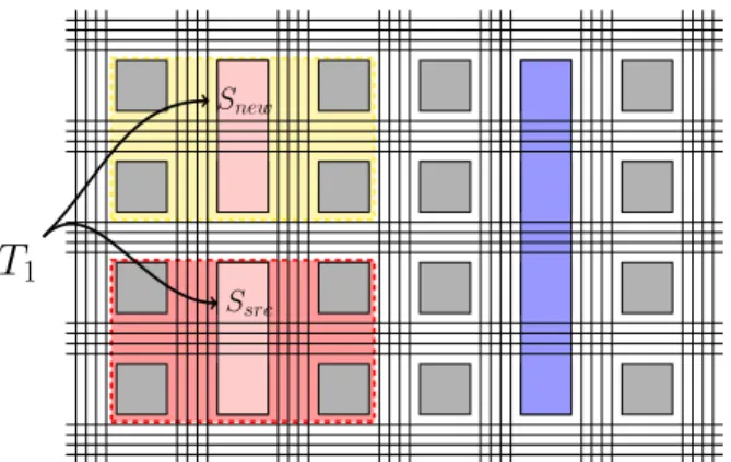
Ssrc
Snew
T
1Fig. 1: Relocation problem in modern FPGAs: task T1, placed on a set Ssrcof resources, is only movable to another set Snew
with resource positions matching those in the original set
• An evaluation of the performance and area over-heads incurred by this routing isolation for a collec-tion of benchmark designs which include components mapped to both FPGA logic and fixed-function re-sources.
A. Background
To promote direct comparisons with contemporary FPGAs, we modify the well-known island-style FPGA model [18]. This architectural model (Figure 1) includes a two-dimensional array of logic blocks (LB) shown in grey squares that are interconnected via a programmable routing network. Our mod-eled LBs include a single four-input lookup table (LUT) and a flip flop (FF), although clusters of LUTs and FFs could also be used. The programmable routing consists of horizontal and vertical channels made of multiple wire segments. The channel segments can be connected to inputs and outputs of the LBs through connection boxes (CB). The channels are also connected to each other via switch boxes (SB). To optimize area and performance, modern FPGAs contain a spectrum of fixed-function blocks (shown as rectangles in Figure 1). These hardware resources reduce the demand for logic blocks for common functions, such as multiplication and bulk memory.
In an island-style FPGA, fixed-function blocks such as block RAMs and signal processing blocks (DSP blocks) are aligned in columns to simplify FPGA layout and the combining of multiple blocks into larger functional resources. Depending on block complexity, the height of a fixed-function block is often larger than a single grid location (e.g. the height of a logic block), as shown in Figure 1.
The allocation of fixed-function blocks across the logic fabric complicates task relocation for the shaded task which spans three columns in Figure 1. Given a hardware task placed at the position (xsource; ysource) in the array, it is
limiting to find a position (xnew; ynew) in the logic fabric
that contain a set of resources Snew with all resources in
exactly the same relative position as Ssource. Overcoming
the restrictions imposed by fixed-function resources requires making the routing connections to the fixed-function blocks more flexible.
LB1 X1 LB2 LB3 Y1 LB4
(a)
LB1 LB2 LB3 LB4
X1 Y1
(b)
Fig. 2: Abstraction of heterogeneous resources: (a) Original logic array (b) Resulting set of logic-only and fixed-function only arrays
B. Fixed-function blocks abstraction
Increased routing flexibility for fixed-function blocks is introduced via an abstracted view of heterogeneous resources. Starting from the original architecture illustrated in Figure 2a, two separate logic resource layers are considered. The first layer, the logic array, includes the logic resources (LBs) of the architecture and its routing network, connection boxes and switch boxes. The second layer is made up of the fixed-function blocks in the baseline logic array (e.g. memory blocks, DSP blocks, communication interfaces, etc.). The
heterogeneousplane has its own routing network, composed of bidirectional routing long lines which span a defined region of the FPGA. Each of these lines can be connected to an input or output of the fixed function blocks. The fixed-function block input and output connections are restricted to their dedicated routing network. Links to the logic array are made via the heterogeneous-only long lines which connect to switch boxes of the logic array routing network. The extent of each of the long lines is optimized to provide good delay performance. The abstraction is presented in Figure 2b. It should be noted that this abstraction does lead to an increase in horizontal delay for routing in the logic-only (homogeneous) plane. Since the positioning on the die of fixed-function blocks is not known at place and route time, it must be assumed that such a block is physically located horizontally between each LB. The additional delay associated with the longer horizontal wires in the homogeneous plane must then be considered.
1) Routing network separation: The heterogeneous-only long lines only carry signals to or from fixed-function blocks. The remaining homogeneous routing network carries signals
Fig. 3: Switch box enhanced to include connections between heterogeneous and homogeneous layers. Red and blue hor-izontal wires (the top four wires) represent heterogeneous-only long lines while the remaining black wires represent homogeneous routing
(a) (b)
(c) (d)
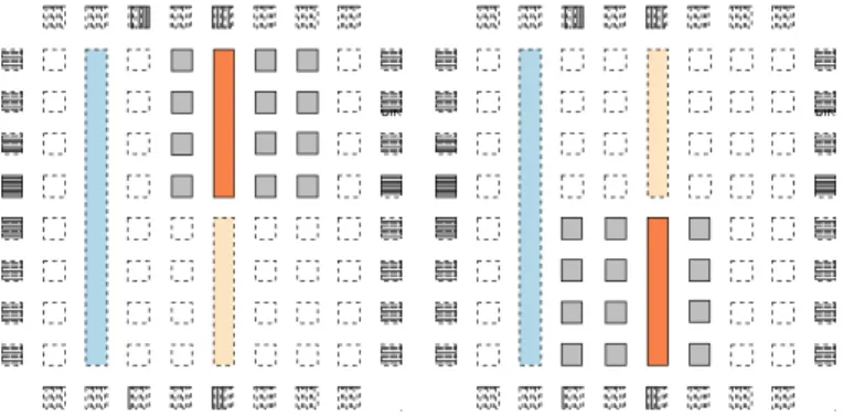
Fig. 4: Multiple relocation possibilities for the same bitstream of a task.
emanating from logic blocks. Heterogeneous-only long lines are connected to the homogeneous routing network through switch boxes at horizontal and vertical channel intersections, as shown in Figure 3. Routing segments spanning multiple LBs (e.g. 2, 4, 8, etc) are commonly found in island-style archi-tectures. These segments do not make intermediate switch box connections to reduce wire delay. However, the heterogeneous-only long lines do connect to multiple adjacent switch boxes. Thus, it is possible to connect to these lines from multiple switch boxes. This additional level of routing allows for the ability to slide a given task horizontally along the horizontal heterogeneous-only long lines without affecting either layer of routing, as illustrated in Figure 4. Only the use of horizontal, heterogeneous-only long lines for fixed-function input and output signals was explored to avoid complex routing and excessive overhead for the overall circuit.
2) Partitioning: Since the size of fixed-function blocks can vary, the vertical and horizontal extent in LBs of a reconfigurable partition must be carefully selected. The width of the partition is bounded by the length of the heterogeneous-only long lines. The height of a partition is defined as the least common multiple of the height of the fixed-function blocks it contains. In this work, the FPGA partitions are identical in size and they are evenly distributed. The partitioning also improves
C
3(3, 1, t
2)
C
2(5, 2, t
2)
C
1(2, 3, t
1)
C
0(4, 4, t
1)
Fig. 5: Task model: each connection Ci has to be linked to a
fixed-function block via heterogeneous-only routing
the scalability of our approach: partitions can be duplicated to extend the size of the logic fabric.
3) Task model: In the context of this paper, we consider a hardware task to be a set of logic resources that are interconnected. A hardware task is described by a bitstream to be loaded into the configurable logic fabric. Unlike standard FPGA development where a hardware task contains an IP block that is loaded into the FPGA at a specific location, in this case a task is an aggregate of both interconnected homogeneous logic resources and a set of connections to heterogeneous-only long lines, as depicted by Figure 5. Each connection is characterized by its position (x, y) within the task and its type t is used to determine its resource connection. This set of connections is fixed, relative to the task itself, and the problem of relocation requires finding a corresponding match of fixed-function resources to this set. A task is defined as T = {Ci(xi, yi, ti)}, where xi, yi is the position of the
connection and ti is its type.
IV. EXPERIMENTAL METHODOLOGY
To experimentally evaluate the impact of our revised FPGA architecture on FPGA area and performance, the Versatile Place and Route (VPR) tool set (version 6.0) was modified. The following subsection details changes made to VPR for experimentation. In subsection IV-B, we describe the set of benchmark designs used for our experiments.
A. Modeling in VPR
The changes made to the VPR source code were made on the latest version1 available in the Verilog To Routing
(VTR) [7] project repository.
1) Architecture: The VPR architecture description XML file that was used to model our circuit is based on k4_N10_memSize16384_memData8.xml, which is one of the default files shipped with the VTR tool flow. The file defines a simplified version of the Stratix IV architecture. The architecture was adapted to suit our needs and to provide a generic FPGA supporting multiple types of fixed-function blocks. The blocks include a36 × 36 multiplier and a config-urable dual-port RAM similar to a Stratix 144 Kbit embedded memory block. Figure 6 demonstrate two placements of the
1The checked out version was revision 3034.
Fig. 6: Two placements of the same task on the enhanced architecture with VPR
same task with VPR and the enhanced architecture; routing was omitted for readability.
2) Routing abstraction: The key modifications to the VPR code base resulted in a dual-layer routing graph which allows inter-layer routing connections at switch boxes (Figure 3).
The segment types of the separated routing networks were modeled using two different segment type definitions in the architecture file. The first segment type, used for homogeneous routing, contains wires which span a single logic block. The second segment, used for heterogeneous-only routing, contains long lines spanning the whole chip. Since we restrict the routing to the fixed-function blocks to horizontal wires, the vertical routing adjacent to the fixed-function blocks is not used. In many VPR architecture definitions, a logic array block will be defined to have its inputs and outputs spread across its four sides. This behavior is undesirable in our case since inputs and outputs on left-hand and right-hand sides of the block will connect to vertical routing channels. As a result, we defined the location of input and output signals for fixed-function blocks as the top and bottom of the block.
Since VPR does not provide support for separate routing networks which are only interconnected in a few locations, modifications were made to the VPR routing graph generator. Source code was modified to enable the marking of segments of the architecture file segmentlist with an additional attribute, selective_routing. This attribute tags the seg-ment as appropriate for either homogeneous signals (i.e. to or from a LB), heterogeneous-only signals (to or from a fixed-function block), or both types. Our model only uses heterogeneous-only long lines and segments which can carry both signal types. Additionally, the graph building procedures were adapted so that input and outputs of the complex blocks marked as heterogeneous are not routed on routing segments which are not tagged to route them. Similar marking was used for homogeneous routing segments.
In the original VPR release, long lines are balanced and their connections are rotated among the wires of the channels in which they reside. This behavior is desirable in an FPGA where one wants to leverage the full routability of the circuit. However, this rotation is not desirable in our model since connections to the heterogeneous-only long lines are more substantial. To circumvent this issue, we disabled the long line balance feature for segments marked as heterogeneous,
TABLE I: VTR design flow benchmark suite
Benchmark Memories Multipliers LBs
LU8PEEng 45 8 2,174 bgm 0 11 2,977 boundtop 1 0 272 ch intrinsics 1 0 41 diffeq1 0 5 43 diffeq2 0 5 30 mkDelayWorker32B 41 0 497 mkPktMerge 15 0 17 mkSMAdapter4B 5 0 181 or1200 2 1 273 raygentop 1 7 192 stereovision1 0 38 990
which allows the wires modeling the fixed-function routing to effectively span a fixed amount of the same columns. Currently, for a given defined segment, VPR will create both horizontal and vertical tracks in the routing graph. For our implementation, only horizontal long lines are used. Although vertical long lines for the heterogeneous-only routing layer were created, they were marked as unusable by the router and their area cost was ignored. All switch block and connection block connections to these wires were removed.
B. Benchmarks
Benchmarks with heterogeneous resources were used to evaluate our modified FPGA architecture. We choose to use the set of benchmarks included in the VTR design flow for experimentation. Among these benchmarks, 12 of them that use heterogeneous blocks (i.e. memories and multipliers) were selected to test our enhanced architecture. Table I sums up the benchmark details. The number of fixed-function blocks was calculated after the packing stage for our architecture. A total of 8 out of 12 designs make use of memories, and 7 out of 12 use multipliers. Of these designs, two of them have more than a thousand logic blocks.
V. RESULTS
In this section we evaluate results obtained with the bench-marks described in Section IV-B using the enhanced archi-tecture detailed in Section III. We use the modified version of VPR described in Section IV-A to perform timing-driven packing, placing and routing for the 12 designs. Comparative results are obtained with respect to a standard architecture which is similar to the enhanced one, with the exception of the new routing for the heterogeneous-only routing. Place and route data concerning the standard architecture are presented in Table II. The basic partition of both architectures is a8×8 array of logic blocks with one column dedicated to a memory of 8 blocks height, and another column containing two multipliers of 4 blocks height. The results of the enhanced architecture were generated with multiple side-by-side horizontal partitions of size8 since this is the smallest common denominator of the logic fabric. Each long line tied to a specific heterogeneous block spans a single partition.
A. Logic array size
As observed in Table III, our enhanced architecture has no influence on the minimal array size (in number of logic blocks) on which a task can be placed.
TABLE II: Place and route benchmark results on the standard architecture
Benchmark Array size Chan. width Crit. delay (ns)
LU8PEEng 56 77 124.06 bgm 64 91 34.66 boundtop 20 36 7.17 ch intrinsics 8 25 3.57 diffeq1 12 32 16.17 diffeq2 12 28 13.84 mkDelayWorker32B 50 65 11.25 mkPktMerge 32 24 5.60 mkSMAdapter4B 18 44 7.34 or1200 25 55 13.36 raygentop 17 45 5.11 stereovision1 37 76 6.24
TABLE III: Place and route benchmark results on the enhanced architecture
Name Size Chan. width H-wire Crit. delay (ns)
LU8PEEng 56 139 (1.81×) 324 134.41 (1.08×) bgm 64 108 (1,19×) 324 35.67 (1.03×) boundtop 20 56 (1.56×) 324 7.51 (1.05×) ch intrinsics 8 25 (1.00×) 162 3.84 (1.08×) diffeq1 12 96 (3.00×) 234 15.96 (0.99×) diffeq2 12 65 (2.32×) 234 12.66 (0.92×) mkDelayWorker32B 50 117 (1.80×) 324 11.46 (1.02×) mkPktMerge 32 92 (3.83×) 324 4.84 (0.86×) mkSMAdapter4B 18 83 (1.89×) 324 7.35 (1.00×) or1200 25 77 (1.40×) 324 13.62 (1.02×) raygentop 17 98 (2.18×) 324 5.78 (1.13×) stereovision1 37 129 (1.70×) 324 6.97 (1.12×) B. Critical delay
The critical delay of each circuit is expressed in nanosec-onds in Tables II and III. To ensure an equal quality of results for both architectures, the same timing driven options were given to VPR, and the same routing seed was used in both cases. Most of the benchmarks sees a critical delay change by less than 10% between the standard architecture and the enhanced one.
The critical path delay increase in Table III is limited and results from routing congestion when vertical routing tracks in the homogeneous routing layer are used to reach the horizontal long lines and the increased capacitance of the long lines for short connections. Some of the benchmarks expose a decrease in critical path delay (in particular diffeq2, mkPktMerge). These improvements originate from the use of long lines to reach heterogeneous blocks, reducing the wire delay for signals in the critical path. The critical path timing of a task must consider relocation-related issues. Since the logic content of a relocatable task is placed relatively to the heterogeneous blocks, we do not know in advance where homogeneous signal will step over a fixed-function block. This issue is addressed at the place-and-route stage through the use of conservative timing.
In our case, the main area impact is a result of the distribution of long lines across the FPGA: a horizontal routing channel contains the minimum number of long lines required to route every I/O of a partition of the biggest channel (i.e. the amount of connections to the most connection-intensive fixed-function block). Long lines which are not tied to a specific I/O in a horizontal channel can be used for other purposes, which
can result in a reduced critical delay.
C. Routing resources
Our approach primarily focuses on routing network en-hancements. The isolation of routing resources for logic-block only and fixed-function blocks has several implications. As described in Section III, each input and output of the fixed-functions blocks is tied to a unique long line of a partition.
We observe an increase in the routing resources needed in the homogeneous routing network (the channel width in Table III), of 1.97× on average. Routing resources due to the routing heterogeneous-only long lines dedicated to fixed-function blocks in the partition are shown in the h-wire column in Table III. It should be noted that the heterogeneous long lines (h-wires) in the table for each benchmark are spread across an entire partition and not isolated in just one channel. As the number of h-wires increases, the number of logic-only homogeneous wires required to route signals up to the long lines increases to avoid network congestion.
Given these results, it is reasonable to define a nominal partition width of 8 columns, including heterogeneous blocks, for this specific architecture, as used in our experiments. This size allows for good performance in terms of flexibility, while still making a good trade-off in routing resources demand and occupied area. Our approach eliminates the need for routing when a task is moved. The only required change for the task bitstream is to shift the homogeneous-to-heterogeneous and heterogeneous-to-fixed-function block connections hori-zontally. The position of these connections in the bitstream can easily be offset by a fixed amount for the hundred or so connections for each fixed-function block as the task is loaded into the device.
VI. CONCLUSIONS ANDFUTUREWORK
This paper presents an enhanced FPGA architecture sup-porting the relocation of tasks and associated partial bitstreams even if the relative position of fixed-function blocks in the target partially-reconfigurable region is changed. A standard island-style FPGA architecture has been expanded to include a dedicated routing layer for fixed-function blocks. Long lines are used in this layer to allow blocks to ”float” horizontally within a region, greatly expanding partially-reconfiguration region placement. The routing implications and costs associ-ated with this freedom have been investigassoci-ated for a variety of VTR benchmarks including fixed-function resources. This architecture is only the first step in the development of a dynamically reconfigurable FPGA for the FlexTiles project which allows for fast task migration and ease-of-use from a designer standpoint. The architecture treats I/Os in addition to multipliers and DSP blocks as fixed-function blocks, necessi-tating our new approach. Future implementations will allow for both horizontal and vertical connections in the heterogeneous-only routing layer. Additionally, research is needed to study the impact of various architectural parameters (e.g. task geometry, routing lines spreading) on detailed performance.
ACKNOWLEDGMENT
This research was sponsored by the European Commission under the 7th Framework program within the FlexTiles project
(FPT ICT-288248) and by the French Ministry of Research. R. Tessier was supported in part by National Science Foundation grant EECS-1201834.
REFERENCES
[1] L. Atieno, J. Allen, D. Goeckel, and R. Tessier, “An adaptive Reed-Solomon errors-and-erasures decoder,” in Proc. ACM/SIGDA
Interna-tional Symposium on Field Programmable Gate Arrays, 2006, pp. 150– 158.
[2] P. Sedcole, P. Y. K. Cheung, G. Constantinides, and W. Luk, “Run-time integration of reconfigurable video processing systems,” IEEE
Transactions on VLSI Systems, vol. 15, no. 9, pp. 1003–1016, 2002. [3] D. Unnikrishnan, R. Vadlamani, Y. Liao, J. Crenne, L. Gao, and
R. Tessier, “Reconfigurable data planes for scalable network virtualiza-tion,” IEEE Transactions on Computers, vol. 62, no. 12, pp. 2476–2488, 2013.
[4] K. Compton, Z. Li, J. Cooley, S. Knol, and S. Hauck, “Configuration relocation and defragmentation for run-time reconfigurable computing,”
IEEE Transactions on VLSI Systems, vol. 10, no. 3, pp. 209 –220, 2002. [5] J.-Y. Mignolet, V. Nollet, P. Coene, D. Verkest, S. Vernalde, and R. Lauwereins, “Infrastructure for design and management of relocat-able tasks in a heterogeneous reconfigurrelocat-able system-on-chip,” in Proc.
Design, Automation and Test in Europe Conference, 2003, pp. 986–991. [6] F. Lemonnier, P. Millet, G. M. Almeida, M. Hubner, J. Becker, S. Pillement, O. Sentieys, M. Koedam, S. Sinha, and K. Goossens, “Towards future adaptive multiprocessor systems-on-chip: an innovative approach for flexible architectures,” in Proc. International Conference
on Embedded Computer Systems, 2012, pp. 228–235.
[7] J. Rose, J. Luu, C. W. Yu, O. Densmore, J. Goeders, A. Somerville, K. B. Kent, P. Jamieson, and J. Anderson, “The VTR project: ar-chitecture and CAD for FPGAs from Verilog to routing,” in Proc.
ACM/SIGDA International Symposium on Field Programmable Gate Arrays, 2012, pp. 77–86.
[8] G. Brebner, “A virtual hardware operating system for the Xilinx XC6200,” in Field-Programmable Logic Smart Applications, New
Paradigms and Compilers, 1996, pp. 327–336.
[9] Increasing Design Functionality with Partial and Dynamic Reconfigu-ration in 28-nm FPGAs, Altera Corporation, 2010.
[10] Partial Reconfiguration User Guide, UG702, Xilinx, Inc., 2013. [11] A. Flynn, A. Gordon-Ross, and A. D. George, “Bitstream relocation
with local clock domains for partially reconfigurable FPGAs,” in Proc.
Design, Automation and Test in Europe Conference, 2009, pp. 300–303. [12] M. L. Silva and J. C. Ferreira, “Creation of partial FPGA configurations at run-time,” in Proc. Euromicro Conference on Digital System Design:
Architectures, Methods and Tools, 2010, pp. 80–87.
[13] J. Carver, N. Pittman, and A. Forin, “Relocation of FPGA partial configuration bit-streams for soft-core microprocessors,” in Workshop
on Soft Processor Systems, 2008.
[14] H. Tan and R. F. DeMara, “A multilayer framework supporting au-tonomous run-time partial reconfiguration,” IEEE Transactions on VLSI
Systems, vol. 16, no. 5, pp. 504–516, 2008.
[15] M. Touiza, G. Ochoa-Ruiz, E.-B. Bourennane, A. Guessoum, and K. Messaoudi, “A novel methodology for accelerating bitstream relo-cation in partially reconfigurable systems,” Microprocessors and
Mi-crosystems, vol. 37, no. 3, pp. 358–372, 2012.
[16] Y. E. Krasteva, E. de la Torre, T. Riesgo, and D. Joly, “Virtex II FPGA bitstream manipulation: Application to reconfiguration control systems,” in Proc. International Conference on Field Programmable Logic and
Applications, 2006, pp. 1–4.
[17] T. Becker, W. Luk, and P. Y. Cheung, “Enhancing relocatability of par-tial bitstreams for run-time reconfiguration,” in Proc. IEEE Symposium
on Field-Programmable Custom Computing Machines, 2007, pp. 35–44. [18] V. Betz, J. Rose, and A. Marquardt, Architecture and CAD for