Automatic target recognition
using passive bistatic radar signals
Jonathan PISANE
Thesis submitted in partial fulfilment of the requirements for the degree
of Doctor of Philosophy (PhD) in engineering sciences of the University
of Liège, and Doctor of Philosophy (PhD) in sciences of SUPELEC.
We present the design, development, and test of three novel, distinct automatic target recognition (ATR) systems for the recognition of airplanes and, more specifically, non-cooperative airplanes, i.e. airplanes that do not provide information when interrogated, in the framework of passive bistatic radar systems. Passive bistatic radar systems use one or more illuminators of opportunity (already present in the field), with frequencies up to 1 GHz for the transmitter part of the systems considered here, and one or more receivers, deployed by the persons managing the system, and not co-located with the transmitters. The sole source of information are the signal scattered on the airplane and the direct-path signal that are collected by the receiver, some basic knowledge about the transmitter, and the geometrical bistatic radar configuration.
The three distinct ATR systems that we built respectively use the radar images, the bistatic complex radar cross-section RCS), and the bistatic radar cross-section (BS-RCS) of the targets. We use data acquired either on scale models of airplanes placed in an anechoic, electromagnetic chamber or on real-size airplanes using a bistatic testbed consisting of a VOR transmitter and a software-defined radio (SDR) receiver, located near Orly airport, France.
We describe the radar phenomenology pertinent for the problem at hand, as well as the mathematical underpinnings of the derivation of the bistatic RCS values and of the construction of the radar images.
For the classification of the observed targets into pre-defined classes, we use either extremely randomized trees or subspace methods. A key feature of our approach is that we break the recognition problem into a set of sub-problems by decomposing the parameter space, which consists of the frequency, the polarization, the aspect angle, and the bistatic angle, into regions. We build one recognizer for each region.
We first validate the extra-trees method on the radar images of the MSTAR dataset, featuring ground vehicles. We then test the method on the images of the airplanes constructed from data acquired in the anechoic chamber, achieving a probability of correct recognition up to 0.99.
We test the subspace methods on the BS-CRCS and on the BS-RCS of the airplanes extracted from the data acquired in the anechoic chamber, achieving a probability of correct recognition up to 0.98, with variations according to the frequency band, the polarization, the sector of aspect angle, the sector of bistatic angle, and the number of (Tx,Rx) pairs used.
The ATR system deployed in the field gives a probability of correct recognition of 0.82, with variations according to the sector of aspect angle and the sector of bistatic angle.
Keywords: Automatic target recognition (ATR), non-cooperative target
recogni-tion (NCTR), classificarecogni-tion, extremely randomized trees (extra-trees), subspace, pas-sive radar, bistatic radar, radar cross-section, complex radar cross-section, illuminator of opportunity, VOR, software-defined radio (SDR), airplanes, anechoic chamber, air traffic control.
This work could not have been performed without the contributions of various persons. These persons all guided me and supported me at some time along my work.
In particular, I wish to thank my two supervisors, Marc Lesturgie, Director of the SONDRA lab of SUPELEC, and Jacques Verly, Professor in the Department of Electricity, Electronics, and Computer Science of the University of Liège, for having accepted to coach me during this thesis. Their advice throughout the entire duration of the thesis was invaluable. I really enjoyed the various discussions we have had, whether technical or not. I hope they have made me a better scientist, a better engineer, and a better person.
I also wish to express my deepest gratitude to Sylvain Azarian for his technical advice throughout the last two years of the thesis, and for his various comments that helped me make this manuscript clearer. I also thank him for his invaluable help during the experiments that could not have been performed without him. I also wish to thank Raphaël Marée for the various discussions we have had on the different classifi-cation techniques, and for his help in understanding extra-trees and the PiXiT software.
I wish to thank Professor Garello, Professor Griffiths, Professor Neyt, Doctor Vignaud, Doctor Walter, and Professor Wehenkel for having accepted to be part of my jury. I am really grateful for the interest they show for my work.
During this thesis, I have had the opportunity to work both at the SONDRA lab of SUPELEC, and among the Department of Electricity, Electronics, and Computer Sci-ence of the University of Liège. Let the people of these two entities be thanked for the nice time I have enjoyed with them. I have had a particularly great time with Frédéric Brigui, Chin Yuan Chong, Jacques El-Khoury, Jérôme Euzière, Pierre Formont, Israël Hinostroza, Mélanie Mahot, Azza Mokadem, and Danny Tan at SONDRA, and with Nicolas Crosset, Géraldine Guerri, Samuel Hiard, Nicolas Marchal, François Schnitzler, and Xavier Werner at the University of Liège. I also wish to thank all the PhD students of the "Réseau des Doctorants" of the University of Liège for the projects we did together, especially the 2009 "Rentrée des Doctorants" and the discussions we have had.
During these four years, I have had the opportunity to coach several MS theses at the University of Liège, in the context of the OUFTI-1 project. Since I believe this experience has enriched me, I would like to thank all the members of such a nice project, and the different students I tried to guide the best I could.
I also wish to thank Anne-Hélène Picot at SONDRA and Marie-Berthe Lecomte, Danielle Bonten, and Sandrine Lovinfosse at the University of Liège for having made the administrative side of my thesis easier to deal with.
Let me also thank the Belgian National Fund for Scientific Research (FRS-FNRS) for having granted me a scholarship of the Fund for Research in Industry and Agriculture (FRIA) during these fours years.
my friends and family, especially Amandine and my parents, for their kindness and understanding during these four years, and especially during the writing of this manuscript.
Finally, I wish to thank all the persons I forgot to mention here.
Table of Contents
Page Abstract i Acknowledgements iii Acronyms xi 1 Introduction 11.1 Motivation for the thesis . . . 1
1.1.1 Targets considered . . . 2
1.1.2 Automatic target recognition (ATR) . . . 2
1.1.3 Class of a target . . . 3
1.1.4 Bistatic radar . . . 3
1.1.5 Passive radar . . . 3
1.2 Developed techniques . . . 5
1.2.1 Scene parameters . . . 5
1.2.2 Quantities used for the recognition of targets . . . 6
1.2.3 Proposed ATR systems . . . 6
1.3 Background: conventional air traffic control (ATC) . . . 8
1.3.1 Primary surveillance radar . . . 9
1.3.2 Secondary surveillance radar . . . 10
1.3.3 Non-cooperative target recognition within ATC . . . 11
1.4 Contributions of the thesis . . . 11
1.5 Organization of the manuscript . . . 12
1.6 Conclusion . . . 13
2 PBR, illuminators of opportunity, and ATR: state-of-art 15 2.1 Passive bistatic radar . . . 15
2.2 Illuminators of opportunity . . . 16
2.3 Automatic target recognition (ATR) . . . 17
2.3.1 Canonical block diagram of a conventional ATR system . . . 17
2.3.2 Adaptation of the canonical block diagram to our problem . . . 18
2.3.3 Input data and classification techniques of ATR systems . . . . 18
2.4 Conclusion . . . 21
3 Bistatic radar phenomenology 23 3.1 Motivation . . . 24
3.2 Notations . . . 24
3.3 Bistatic scattering geometry . . . 24
3.5 Scattering mechanisms . . . 27
3.6 Scattering regions . . . 30
3.7 BS-RCS of a perfectly conducting sphere . . . 31
3.7.1 Hypotheses . . . 32
3.7.2 Transmitted electric and magnetic fields . . . 33
3.7.3 Scattered electric field . . . 35
3.7.4 BS-CRCS and BS-RCS as a function of the bistatic angle . . . . 38
3.7.5 Application to the case of the perfectly conducting sphere . . . 40
3.7.6 BS-RCS of canonical objects . . . 41
3.8 Monostatic-to-bistatic equivalence theorems . . . 42
3.9 Conclusion . . . 42
4 Extraction and illustrations of the bistatic RCS of targets 45 4.1 Motivation . . . 46
4.2 Extraction of the BS-CRCS and the BS-RCS of targets . . . 47
4.2.1 Transmitted electric field . . . 47
4.2.2 Polarization . . . 48
4.2.3 Expressions for the Tx and Rx E-fields . . . 50
4.2.4 Bistatic polarization scattering matrix . . . 52
4.2.5 Components of the bistatic polarization scattering matrix . . . . 53
4.2.6 Bistatic complex RCS . . . 55
4.2.7 Bistatic polarization CRCS matrix . . . 56
4.2.8 Position of the Tx as reference for the Tx electric field . . . 57
4.2.9 Case of a single linear polarization . . . 58
4.2.10 Practical measurement of the BS-RCS of targets . . . 59
4.3 Acquisition of raw data: experimental setup . . . 59
4.3.1 Motivation for using scaled models in an anechoic chamber . . . 59
4.3.2 Configuration geometry . . . 60
4.3.3 Acquisition of raw data . . . 61
4.3.4 Airplanes of interest . . . 63
4.4 Scattering regions . . . 65
4.5 Classes of airplanes . . . 65
4.6 Illustration of the BS-CRCS and the BS-RCS of targets . . . 66
4.6.1 BS-CRCS as a function of the bistatic angle . . . 66
4.6.2 BS-CRCS as a function of the frequency . . . 69
4.6.3 BS-CRCS as a function of the polarization . . . 73
4.6.4 BS-CRCS as a function of the orientation . . . 73
4.6.5 Conclusions about the variations of BS-CRCS . . . 75
4.7 Conclusion . . . 77
5 Construction of radar images 79 5.1 Motivation . . . 79
5.2 Review of tomographic imaging . . . 80
5.2.1 The Radon Transform . . . 80
5.2.2 The 2DFT and its rotation property . . . 80
5.2.3 The projection-slice theorem . . . 82
5.3 Principles of monostatic radar imaging . . . 84
5.3.1 Monostatic (MS) configuration . . . 84
5.4 Principles of bistatic radar imaging . . . 87
5.4.1 Bistatic (BS) configuration . . . 87
5.4.2 Bistatic (BS) imaging . . . 88
5.5 Practical construction of bistatic radar images . . . 90
5.6 Examples of constructed radar images . . . 94
5.7 Conclusion . . . 97
6 Recognition of targets by using their radar images 99 6.1 Motivation . . . 100
6.2 Physical and parameter spaces . . . 101
6.2.1 Physical space . . . 101
6.2.2 Parameter space . . . 105
6.3 Recognition strategy . . . 106
6.4 Block diagram of the recognizer . . . 111
6.5 Production of feature vectors by window extraction . . . 112
6.6 Determination of target class model by extra-trees . . . 113
6.6.1 Deterministic decision tree . . . 113
6.6.2 Extremely randomized trees . . . 114
6.6.3 Motivation for using extremely randomized trees . . . 115
6.7 Determination of the target class . . . 116
6.8 Quantification of performance . . . 116
6.9 Recognition experiments on MSTAR images . . . 117
6.9.1 Description of MSTAR images . . . 117
6.9.2 Experimental sets of images . . . 117
6.9.3 Parameters of the recognizer . . . 120
6.9.4 Recognition results . . . 120
6.10 Recognition experiments on ONERA images . . . 127
6.10.1 Experimental sets of images . . . 127
6.10.2 Parameters of the recognizer . . . 128
6.10.3 Recognition results . . . 128
6.11 Conclusion . . . 136
7 Recognition of targets by using their bistatic RCS or CRCS 139 7.1 Motivation . . . 140
7.2 Block diagram of the recognizer . . . 141
7.3 Production of feature vectors . . . 142
7.4 Determination of target class model by vector spaces . . . 143
7.4.1 Motivation for using subspace methods . . . 143
7.4.2 Subspaces . . . 143
7.4.3 Size of subspaces . . . 145
7.5 Determination of the target class . . . 145
7.5.1 Orthogonal projection . . . 146 7.5.2 Metrics . . . 147 7.5.3 Oblique projection . . . 148 7.6 Quantification of performance . . . 148 7.7 Recognition experiments . . . 149 7.7.1 Experimental sets . . . 149
7.7.2 Recognition results achieved for a single (Tx,Rx) pair . . . 149
7.8 Conclusion . . . 167
8 Recognition of targets by using their real-life bistatic RCS 169 8.1 Motivation . . . 170
8.2 Block diagram of the ATR system . . . 171
8.3 Detection, discrimination, and pre-classification . . . 171
8.4 Classes of targets . . . 172
8.4.1 Types of detected airplanes . . . 172
8.4.2 Grouping of targets into classes . . . 174
8.5 Scene parameters . . . 176
8.6 Extraction of the BS-RCS . . . 176
8.6.1 Extraction of the BS-RCS from real-life data . . . 176
8.6.2 Generation of the BS-RCS from a simple model . . . 180
8.7 Recognition stage . . . 180
8.8 Experimental setup . . . 181
8.8.1 Testbed . . . 181
8.8.2 The VOR as a simple illuminator of opportunity . . . 181
8.8.3 Collecting the received signals by an SDR receiver . . . 183
8.8.4 Digital processing of received signals . . . 183
8.9 Data collected and examples of received signals . . . 184
8.9.1 Data available for our recognition experiments . . . 184
8.9.2 Received ADS-B data . . . 185
8.9.3 Spectrograms . . . 185
8.9.4 Signal-to-noise-ratios . . . 187
8.9.5 Variations of the BS-RCS as a function of time . . . 189
8.9.6 Distributions of the BS-RCS in (α, β) plane . . . 189
8.10 Errors on position, bistatic angle, and BS-RCS . . . 193
8.10.1 Error on the position of a target . . . 193
8.10.2 Influence of the error in position on the bistatic RCS . . . 193
8.10.3 Reasons for using the BS-RCS instead of the BS-CRCS . . . 196
8.11 Recognition experiments performed . . . 196
8.11.1 Amount of data . . . 197
8.11.2 Statistics of the feature vectors and brief analysis thereof . . . . 202
8.11.3 Recognition results for the three-class experiment . . . 202
8.11.4 Recognition results for all four recognition experiments . . . 208
8.12 Conclusion . . . 208
9 Conclusions and perspectives 211 9.1 Conclusions . . . 211
9.1.1 Summary of the thesis . . . 211
9.1.2 Comparison of the performances of the three ATR systems . . . 213
9.2 Perspectives . . . 214
9.2.1 Addition of different types of targets . . . 215
9.2.2 Study of bistatic radar phenomenology . . . 215
9.2.3 Use of different illuminators of opportunity . . . 215
9.2.4 Refinement of the recognizer . . . 216
Appendices 219
B Publications 231 B.1 Journal articles . . . 231 B.2 Conference papers . . . 231 B.3 Other publications . . . 232 Bibliography 233 ix
Acronyms
ADC Analog-to-Digital Converter ADS Automatic Dependent Surveillance
ADS-B Automatic Dependent Surveillance - Broadcast AM Amplitude Modulation
APC Armored Personal Carrier
AREPS Advanced Refractive Effects Prediction System ASR Automatic Surveillance Radar
ATC Air Traffic Control
ATR Automatic Target Recognition BS BiStatic
BS-CRCS Bistatic Complex Radar Cross-Section
BS-PCRCSM Bistatic Polarization Complex Radar Cross-Section Matrix BS-PSC Bistatic Polarization Scattering Coefficient
BS-PSM Bistatic Polarization Scattering Matrix BS-RCS Bistatic Radar Cross-Section
BS-SC Bistatic Scattering Coefficient BS-SM Bistatic Scattering Matrix BTS Base Transceiver Station CFAR Constant False Alarm Rate CPR Compact Position Reporting CRCS Complex Radar Cross-Section CW Continuous Wave
DAB Digital Audio Broadcast
DVB-T Digital Video Broadcast - Terrestrial E-field Electric field
EM-field ElectroMagnetic field EVD EigenValue Decomposition extra-tree Extremely randomized tree FFT Fast Fourier Transform
FISC Fast Illinois Solving Code FM Frequency Modulation FT Fourier Transform FV Feature Vector H-field Magnetic field HF High Frequency
HRR High Range Resolution
ICAO International Civil Aviation Organization IF Intermediate Frequency
IFF Identification Friend-or-Foe kNN k-Nearest Neighbors
LADAR LAser Detection And Ranging LDA Linear Discriminant Analysis LOS Line-Of-Sight
LS Learning Set
MAP Maximum A Posteriori
MBET Monostatic-to-Bistatic Equivalence Theorem MDA Multiple Discriminant Analysis
MS MonoStatic
MS-CRCS Monostatic Complex Radar Cross-Section MS-RCS Monostatic Radar Cross-Section
MTD Moving Target Detector MTI Moving Target Indicator
NCTR Non-Cooperative Target Recognition NEC Numerical Electromagnetic Code NN Neural Networks
PBR Passive Bistatic Radar
PCA Principal Component Analysis PCL Passive Coherent Location PPI Plan-Position Indicator PSR Primary Surveillance Radar PST Projection-Slice Theorem RCS Radar Cross-Section RF Radio Frequency RT Radon Transform Rx Receiver
SAR Synthetic Aperture Radar SDR Software-Defined Radio SNR Signal-to-Noise Ratio
SSR Secondary Surveillance Radar SVD Singular Value Decomposition SVM Support Vector Machine
TCAS Traffic alert and Collision Avoidance System TRO Time Reversal Operator
TS Test Set Tx Transmitter
VHF Very High Frequency VOR VHF Omni-Range
Chapter 1
Introduction
Contents
1.1 Motivation for the thesis . . . . 1
1.1.1 Targets considered . . . 2
1.1.2 Automatic target recognition (ATR) . . . 2
1.1.3 Class of a target . . . 3
1.1.4 Bistatic radar . . . 3
1.1.5 Passive radar . . . 3
1.2 Developed techniques . . . . 5
1.2.1 Scene parameters . . . 5
1.2.2 Quantities used for the recognition of targets . . . 6
1.2.3 Proposed ATR systems . . . 6
1.3 Background: conventional air traffic control (ATC) . . . . 8
1.3.1 Primary surveillance radar . . . 9
1.3.2 Secondary surveillance radar . . . 10
1.3.3 Non-cooperative target recognition within ATC . . . 11
1.4 Contributions of the thesis . . . . 11
1.5 Organization of the manuscript . . . . 12
1.6 Conclusion . . . . 13
1.1
Motivation for the thesis
The motivation for this thesis is the automatic recognition of targets using passive bistatic radar signals. The objective of the thesis is to design, implement, and test a system able to recognize, at low cost, targets. We call this system an automatic target recognition (ATR) system. In this section, we define the types of targets that are considered, and the notions of ATR, target class, bistatic radar, and passive radar.
1.1.1
Targets considered
In this work, we consider non-cooperative targets. Non-cooperative targets are targets that do not provide information about their identity or location when asked to do so, by contrast with cooperative targets that provide this information. Examples of non-cooperative targets are personal cars. In general, we often refer to targets as objects.
Without loss of generality, we consider non-cooperative air targets. Non-cooperative air targets are not able to reply to requests from air traffic control (ATC) radars, either because of the absence of a transponder on-board, because of a failure of such a transponder, or because the transponder is off (willingly or not). ATC is described in Section 1.3. We discuss the application of the proposed ATR systems, described in Section 1.2, to other types of targets in Chapter 9.
1.1.2
Automatic target recognition (ATR)
Automatic target recognition (ATR) is defined as the process of recognizing targets without human involvement [17, 95, 173]. ATR is called non-cooperative target recog-nition (NCTR) in case of non-cooperative targets, as in this thesis, and identification friend-or-foe (IFF) in case of cooperative targets [187]. NCTR aims at recognizing a target from the radar echo signals received from the target to be recognized. IFF systems rely on the interrogation of the transponder on-board the target that sends its identification back to the interrogator.
The word "recognition" in ATR implies classification. We equivalently use both terms in this thesis. Classification is defined as the act of assigning to input data one class among a set of pre-defined classes [54,134]. The task of the classifier is to assign a class to an unknown object described by features, called attributes. To do so, the clas-sifier derives rules from objects described by attributes and for which their respective class is known. Usually, a classification model describing these rules is derived using a subset of the available data called the learning set (LS). The classification model is tested on another subset of the data called the test set (TS). Other ways of partitioning the data, such as cross-validation, can be used [134]. Cross-validation is used when the amount of data is insufficient to create an LS and a TS that are independent, and that each contains a sufficient amount of objects. We do not consider cross-validation in this thesis since a particular effort is made to obtain a dataset as complete as possible. The fact that we learn and train the ATR systems, described in Section 1.2, on real data, making up complete datasets, is another key feature of this thesis. Indeed, as will be explained in Chapter 2, many ATR systems for passive radar rely on simulated data.
Classification is a part of supervised learning [54, 134]. In supervised learning problems, objects belong to different categories, called classes. Supervised learning aims at deriving relationships between the attributes of objects. These relationships are used to predict the true class of an object. Supervised learning problems are either regression problems or classification problems. In regression problems, the prediction is a (continuous) numerical value, whereas in classification problems the predicted output is a discrete class.
Supervised learning is a part of machine learning. Machine learning is a subfield of automatic learning that aims at designing rules that are similar to those that human experts derive [221]. In machine learning problems, each object is characterized by a set of features called attributes. Machine learning is divided into supervised learning and unsupervised learning. Unsupervised learning, also called clustering, aims at deriving probabilistic or causal relationships between objects. For example, clustering methods try to form groups of objects based on the features of the objects. The use of unsupervised learning in our ATR problem is part of our future work, and is discussed in Chapter 9.
In short, the problem addressed in this thesis is an ATR problem, and more specif-ically, an NCTR problem. We aim at classifying/recognizing non-cooperative air tar-gets. Air targets are characterized by some number of attributes.
1.1.3
Class of a target
In this work, the proposed ATR systems label each unknown target of interest with a particular target class. The notion of target class is not uniquely defined in the radar ATR literature. The nature of the prediction of a classifier thus varies from one ATR system to the other. For example, a target is defined in [187] first according to its general nature, which can be defined as aircraft, ship, or bird. Each type of general nature of target is then divided into different target types. Example target types for airplanes are fighter planes and helicopters. Each target type can be further separated into different target classes that can be F16, F22, and B2. The callsign of a target, such as AF123, can eventually be determined. This latter operation is referred to as identification, and not as classification/recognition. Identification is usually implemented in a cooperative target recognition system (IFF), since it requires the target to send its identification number or identification code.
In this thesis, we use a single target class for all airplanes sharing the same physical properties. Looking ahead to Chapter 8, large-size airplanes and mid-size airplanes shall be labelled two different classes, while an A318 airplane and an A319 airplane shall be labelled the same class, since they are both mid-size airplanes.
1.1.4
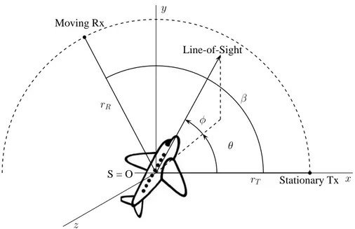
Bistatic radar
A radar system is called bistatic (BS) when the transmitter and the receiver are not co-located, as shown in Fig. 1.1, by contrast with the monostatic (MS) radar for which the transmitter and the receiver are co-located [89]. By comparison with MS configurations, a BS configuration is characterized by an additional parameter, which is the bistatic angle, β. The bistatic angle β is defined as the angle (defined to be positive and less than 180◦) between the transmitter and the receiver, with its vertex
at the target [224].
1.1.5
Passive radar
Passive radars are radars that use illuminators of opportunity as transmitters. Illu-minators of opportunity are transmitters that are already present in the environment,
Target
Baseline
Transmitter Receiver
Transmission path β Echo path
Figure 1.1: Bistatic geometry for one pair of transmitter and receiver.
such as analog TV transmitters, digital video broadcast - terrestrial (DVB-T) TV transmitters, or mobile phone base transceiver stations (BTSs). We propose to use one or multiple illuminators of opportunity as source of radar illumination, as in [225]. It is assumed that the different characteristics of the signals transmitted illuminators of opportunity, such as their location, frequency, modulation, and polarization are known but are not controlled.
The qualifier "passive" means that the transmitter is not aware of being used as a radar transmitter, although it must evidently be active. The transmitter is thus called non-cooperative. The different illuminators of opportunity that are used in actual passive radar systems are presented in Chapter 2.
Since the transmitter used is already present, the implementation of a passive radar requires few technical investments, especially since fast digital signal processors that make the acquisition and the processing of the scattered signals easy are available. Using illuminators of opportunity thus contributes to the low-cost aspect of the solution. Another advantage of a passive radar is that, since the transmitter is already operational, it allows for an immediate access to the frequency spectrum. The main disadvantage is that the characteristics of the signal transmitted are not controlled, since such a transmitter is usually not designed specifically for radar purposes.
Illuminators of opportunity considered in this work operate on the "low" frequency bands, defined here as frequencies lower than 1 GHz. The use of low frequencies for classification/recognition purposes is justified by the following reasons. First, since the wavelength is of the order of several meters, and since the length of the targets are of the order of tens of meters, the radar signature and its variations are essentially dependent on the larger parts of a target, and less sensitive to its smaller parts. The signature is thus robust and reproducible from one aircraft to the other at low frequencies. Second, transmitters operating at low frequencies are present everywhere in the environment: radio transmitters, TV transmitters, mobile phone BTSs. Therefore, the use of signals transmitted at these corresponding frequencies is straightforward. Third, low frequencies are suitable to defeat the possible stealthiness of air targets. Indeed, at low frequencies, no material can efficiently absorb the energy of the incident wave and be used in operation. Absorbing energy at these low
frequencies would require that the size of the stealth layer be very large, of the order of the wavelength, i.e. of about 3 m for a signal transmitted at a frequency of 100 MHz.
Passive radars are inherently bistatic. Such radars are called passive bistatic radars (PBRs). As explained in Chapter 2, PBRs are mainly used today for detection and location purposes. The use of PBRs for the recognition of air targets is a key feature of this thesis.
1.2
Developed techniques
We use radar signals transmitted by one or multiple transmitters (Tx’s) of oppor-tunity, scattered by a target, and collected by one or multiple receivers (Rx’s). The configuration of the radar system is shown in Fig. 1.2 for a single (Tx,Rx) pair. The three ATR systems implemented in this thesis assign a class to the unknown, detected air target from the signal scattered by this air target and from the direct signal. The performances of the three proposed ATR systems will be compared in Chapter 9, in terms of (1) their probabilities of correct recognition, defined as the ratio of the number of objects correctly recognized to the total number of objects, and (2) the number of (Tx,Rx) pairs needed.
Figure 1.2: Configuration of the radar system for a single (Tx,Rx) pair. An ATR
system assigns a class to the unknown, detected air target based on the received scattered signal.
1.2.1
Scene parameters
We assume that an unknown airplane to recognize has already been detected and tracked: we know its position and line-of-sight, i.e. its direction. However, we do not know its exact orientation, i.e. its yaw, pitch, and roll angles. These assumptions are realistic since the detection and tracking of an airplane is performed by a primary
surveillance radar (PSR) when the airplane is taking-off or landing, as described in Section 1.3. When the airplane is en-route, passive bistatic radars (PBRs) can detect and track airplanes, as explained in Chapter 2.
We assume that we know the location, polarization, and frequency of the Tx(s) of opportunity used, but we do not control them. We also assume that we know the location and polarization of the Rx(s), since the Rx(s) are under our full control. We call these parameters the scene parameters.
1.2.2
Quantities used for the recognition of targets
Consider the case of a PBR consisting of a single Tx of opportunity and a single Rx. One can extract, from the signal transmitted by the Tx, scattered by the unknown, detected air target, and collected by the Rx, the bistatic complex radar cross-section (BS-CRCS) and the bistatic radar cross-section (BS-RCS), which both characterize the target. We present the notions of BS-CRCS and BS-RCS in Chapter 3. The extraction of both the BS-CRCS and the BS-RCS from the signal scattered by an (air) target is explained in Chapter 4.
As described in Chapter 2, images of targets are often used in ATR. The radar image of a target is defined as a two-dimensional (2D) BS-CRCS density. We thus first perform the recognition of targets by using their radar images constructed from their BS-CRCS.
However, constructing radar images of air targets based on signals transmitted by illuminators of opportunity is difficult, as the required space and frequency diversity constraints (described in Chapter 5) would be difficult to meet in an operational system. Therefore, in a second step, we suggest to recognize targets by using either their BS-CRCS or their BS-RCS.
We test the first two ATR systems on data acquired in an anechoic chamber. For the third ATR system, we recognize targets by using their real-life BS-RCS, since, as shown in Chapter 8, the phase of the BS-CRCS is difficult to acquire in an operational, outdoor ATR system.
1.2.3
Proposed automatic target recognition (ATR) systems
We present three ATR systems. The three systems share the following characteristics:
• The raw input data of each ATR system consists of the signals transmitted by an illuminator of opportunity, scattered by a detected air target, and collected by a receiver. The input data is separated into a learning set (LS), and a test set (TS).
• The scene parameters are known, and are an input of each of the three ATR systems.
• The recognition, that we also call the classification, consists in a learning step and a test step. The learning step consists in the construction of the target class
model based on data in the LS. The test step consists in the determination of the target class of data in the TS, thus attributing a class to each data instance of the TS.
• The output of each of the three ATR systems is the class of the unknown, detected air target. We quantify the performance of each of the three ATR systems by computing the probability of correct recognition for each.
The three following subsections give a block diagram of each of our three ATR systems, as well as the characteristics of each of them.
ATR system using radar images
Our first ATR system recognizes targets by using their radar images. We will use this system as a reference to evaluate our two other ATR systems, which recognize targets by using either their BS-CRCS or their BS-RCS.
Figure 1.3 shows the block diagram of this first ATR system. The BS-CRCS of the targets are extracted from the raw input data, for both the LS and the TS (Chapter 4). The images of targets are then constructed from these BS-CRCS (Chapter 5). The images in the LS are used to generate the target class model. The target class of each image of the TS is determined by passing each image in the TS through the target class model (Chapter 6).
Figure 1.3: Block diagram of our ATR system using radar images of targets.
ATR system using either bistatic complex RCS (BS-CRCS) or bistatic RCS (BS-RCS)
Since the construction of images of targets is not feasible in an operational low-frequency passive bistatic radar system, as will be described in Chapter 5, we recognize targets by directly using either their BS-CRCS or their BS-RCS. Figure 1.4 shows the block diagram of our second ATR system. The BS-CRCS or the BS-RCS of the targets are extracted from the raw input data, for both the LS and the TS (Chapter 4). The class of unknown targets is determined by passing either their BS-CRCS or their BS-RCS through the target class model (Chapter 7).
Figure 1.4: Block diagram of our ATR system using the bistatic complex radar
cross-sections or the bistatic radar cross-cross-sections of targets.
ATR system using real-life bistatic radar cross-sections (BS-RCSs)
In order to design an operational ATR system, we add a detection stage and a discrimination and pre-classification stage to the second ATR system, as shown in Fig. 1.5. This ATR system, that we discuss in Chapter 8, will be tested in an operational mode. For reasons to be explained in Chapter 8, we use the BS-RCS and not the BS-CRCS of air targets.
Figure 1.5: Block diagram of our ATR system using real-life bistatic radar
cross-sections of targets.
We perform the discrimination between detected targets of interest and other de-tected man-made targets in the discrimination and pre-recognition stage. The BS-RCS of the targets of interest are extracted in the extraction of BS-RCS stage, and are the input of the recognition stage. The class of targets of interest is determined by passing their BS-RCS through the target class model.
1.3
Background:
conventional air traffic control
(ATC)
In this thesis, we address the problem of the recognition of non-cooperative targets, called non-cooperative target recognition (NCTR). Since the targets considered in this work are air targets, we describe the principles of air traffic control (ATC).
In Europe, ATC is performed by secondary surveillance radars (SSRs) when air-planes are en-route. Around airports, i.e. for take-off and landing operations, ATC is performed by airport surveillance radars (ASRs), consisting in the joint use of pri-mary surveillance radars (PSRs) and SSRs. In the United States, ASRs are used both en-route and near airports [204]. We now briefly describe PSRs and SSRs, in order to point out their limitations for ATC for the recognition of non-cooperative airplanes.
1.3.1
Primary surveillance radar
A primary surveillance radar (PSR), also called moving target detector (MTD), is a particular type of moving target indicator (MTI) radar [187, 204]. As for any radar, it sends out electromagnetic pulses. If an (air) target is present, the surface of this target will reflect the incident pulse back to the radar. The time taken by the pulse to reach the target and return to the PSR gives the distance from the radar antenna to the target according to
D = cτ
2, (1.1)
where D is the distance from the antenna to the target, c the speed of light, and τ the round-trip delay.
The bearing of the target is given by the azimuth orientation of the PSR antenna. The elevation angle of the target is not measured. The PSR radar scans the entire horizon at some scan rate, which means that a particular portion of the sky is not continuously monitored, therefore limiting the dwell time.
Figure 1.6 shows the key stages of a PSR radar [137]. First, the signal scattered on the target is digitized by an analog-to-digital converter (ADC). Second, the signal scattered on the target is separated from clutter by using clutter cancellation filters, such as digital Doppler filters. Then, the signal scattered on the target is separated from thermal noise using a constant false alarm rate (CFAR) thresholding algorithm. A scan-to-scan correlation-and-tracking algorithm generates a single report per target, from a cluster of range-azimuth-Doppler target reports, so that a target is represented by a single dot on the plan-position indicator (PPI).
Figure 1.6: Simplified block diagram of a primary surveillance radar.
The main advantage of the PSR is that it does not require the cooperation of the target itself. It is also capable of detecting small energy responses, making it available to monitor weather. The main disadvantage of the PSR is its inability to discriminate
between targets presenting the same level of return energy. Another disadvantage of the PSR is the large amount of transmitting power required so that the echo signal has a power high enough to be measurable. This limits its range. Moreover, echo signals are subject to external factors such as changes of target attitude, resulting in fading of these echo signals.
1.3.2
Secondary surveillance radar
A secondary surveillance radar (SSR) is used to identify an air target, whether it has been detected by a PSR radar [192] if the air target is near airports, or not if it is en-route. SSRs can be seen as the civilian adaptation of the military identification friend-or-foe (IFF) radar systems that were initially developed during World War II [68]. During this war, air targets equipped with IFF systems had to respond with a specific signal to signals transmitted by ground-based transmitters. A correct response made the aircraft be identified as friend, while an incorrect response made the aircraft be identified as foe.
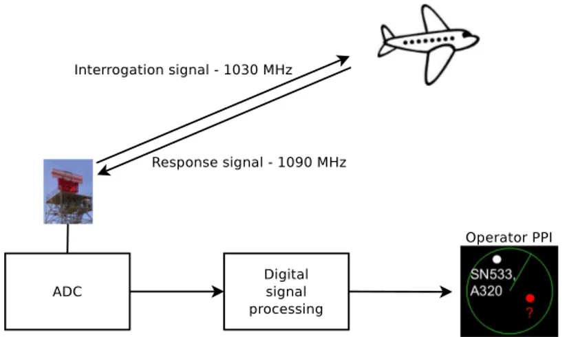
Figure 1.7 shows the principle of an SSR. The SSR transmitter sends out an inter-rogation signal to the transponder (transmitter/receiver working on radar frequencies) carried aboard the cooperative target. The on-board transponder responds to the SSR interrogation by sending a signal containing information such as the target identity (squawk code) and position. Upon reception, the response signal is processed by the receiver in order to identify the target on the operator plan-position indicator (PPI). If the target transponder does not respond, it is considered as a non-cooperative target in civilian aviation, and as an enemy in military aviation.
Figure 1.7: Simplified block diagram of the receiving stage of a secondary surveillance
radar.
The main advantage of the SSR is that the transmitting power from the SSR transmitter can be reduced. Indeed the power of the received signal decreases by a factor of D2 instead of D4 in the PSR case, since both the radar and the target
transmit in the SSR case. Another advantage is the complete identification and location of the air target through the information sent from the target.
The automatic dependent surveillance (ADS) system is the SSR used today. An ADS system relies on a transponder aboard an air target that transmits data, such as its position, altitude, and speed, to the ground station. Today, the automatic dependent surveillance- broadcast (ADS-B) mode [22, 209], which is part of the new Traffic Alert and Collision Avoidance System (TCAS), is used [9].
1.3.3
Non-cooperative target recognition (NCTR) within air
traffic control (ATC)
As described above, the identification process is based on the presence of a transponder aboard the air target, and on the confidence in the response from such transponder. In case there is no transponder aboard the target, or its transponder is not working properly, or it is turned off, the target cannot be identified.
Near airports, one could think of analyzing the signals transmitted by the PSR and scattered by the air target back to the PSR to characterize the target. However, for conventional and existing PSRs, as the scan rate is high, the dwell time is limited, of the order of a few milliseconds. Moreover, as the range is important, the distance resolution is also low. It is therefore difficult to analyze the target using a PSR, and even more difficult to create an image or a high-resolution range profile of the target to recognize it. Furthermore, because of the limited "time-on-target", PSRs will not be used as transmitters of opportunity.
However, studies aiming at designing new PSRs that would be able to combine both tracking and identification modes within the same scan are currently on-going. These new PSRs are not considered here, as they are not operational yet.
In conclusion, the use of conventional PSRs and SSRs does not allow one to identify non-cooperative targets. Moreover, even though SSRs are able to identify cooperative targets, SSRs do not provide any verification mean, since SSRs trust the information received from the target transponder.
1.4
Contributions of the thesis
We list here the main contributions of the thesis. First, we use low-frequency passive bistatic radar signals for the classification/recognition of air targets. Indeed, many passive bistatic radar signals are used for the detection and location of targets, but not for their recognition. The use of illuminators of opportunity contributes to the low-cost aspect of the proposed solution. The use of low-frequency radar signals for the recognition of targets is not common, since many automatic target recognition (ATR) systems operate at higher frequencies.
Our first ATR system recognize targets by using their radar images. Although the expression for the construction of the radar image of a target from its bistatic complex radar cross-section (BS-CRCS) is known, we provide its derivation from the principles of tomographic imaging, as second contribution. The reason is that we could not find this derivation in the literature.
Third, we recognize non-cooperative air targets, based on either their BS-CRCS or their bistatic radar cross-section (BS-RCS). This is a major difference with many ATR systems that mainly use either high-resolution range profiles or radar images of targets.
Fourth, we developed three ATR systems that use two recognition techniques, which are the extremely randomized trees and the subspace methods. To the best of our knowledge, the use of tree-based classification methods in the radar ATR domain is novel. To the best of our knowledge, vector subspaces are mainly used in the radar domain for detection, and not for classification/recognition.
Fifth, we learn and train the recognition stage of each of our three ATR systems on real data.
Sixth, we deploy a passive bistatic radar that we use for the acquisition of real-life passive bistatic radar signals. We extract the real-life BS-RCS of commercial airplanes from these signals.
1.5
Organization of the manuscript
Chapter 2 presents a literature review of passive bistatic radars, illuminators of opportunity, and automatic target recognition (ATR).
Chapter 3 presents the notions of bistatic complex radar cross-section (BS-CRCS) and bistatic radar cross-section (BS-RCS), and their variations according to different physical parameters. The reason is that our three ATR systems rely on either the BS-CRCS or the BS-RCS of targets.
Chapter 4 presents the extraction of both the BS-CRCS and the BS-RCS of targets, and illustrates experimentally the variations of both the BS-CRCS and the BS-RCS of air targets as a function of different physical parameters.
Chapter 5 presents the theoretical and practical computation of the radar images of targets from their BS-CRCS, for both a monostatic configuration and a bistatic configuration.
Chapter 6 presents the design, implementation, and test of the recognition stage of the ATR system recognizing targets by using their radar images.
Chapter 7 presents the design, implementation, and test of the recognition stage of the ATR system recognizing targets by using either their BS-CRCS or their BS-RCS.
Chapter 8 presents the design, implementation, and test of the ATR system recognizing targets by using their real-life BS-RCS. This chapter also presents the experimental testbed we implemented to acquire real-life, outdoor passive bistatic radar signals from which we extract the BS-RCS of the air targets of interest.
performances of our three ATR systems, and discusses future developments to be per-formed to validate an operational ATR system based on passive bistatic radar signals.
1.6
Conclusion
In this chapter, we presented the motivation for this thesis, which consists in the low-cost classification/recognition of non-cooperative air targets. We recognize such air targets by the use of signals transmitted by low-frequency illuminators of opportunity, and scattered by these air targets. The automatic target recognition (ATR) systems proposed here thus use passive bistatic radar. The notions of ATR, target class, passive radar, and bistatic radar were defined.
We presented three different ATR systems. The input of each ATR system consists in the known parameters of the scene, and in the signals scattered by an air target. The output of each ATR system consists in the class of this unknown air target. The three ATR systems recognize targets by respectively using their radar images, their bistatic complex radar cross-section (BS-CRCS), and their bistatic radar cross-section (BS-RCS).
Since we consider non-cooperative air targets, we briefly described some key principles of air traffic control (ATC), which is based on primary surveillance radars (PSRs) and secondary surveillance radars (SSRs). We discussed the reasons why current PSRs and SSRs cannot be used for the recognition of non-cooperative air targets.
We listed the contributions of this thesis, and we presented the organization of this manuscript.
Chapter 2
Passive bistatic radar, illuminators
of opportunity, and automatic
target recognition: state-of-art
Contents
2.1 Passive bistatic radar . . . . 15
2.2 Illuminators of opportunity . . . . 16
2.3 Automatic target recognition (ATR) . . . . 17
2.3.1 Canonical block diagram of a conventional ATR system . . . 17 2.3.2 Adaptation of the canonical block diagram to our problem . . 18 2.3.3 Input data and classification techniques of ATR systems . . . 18
2.4 Conclusion . . . . 21
In this chapter, we review the literature about passive bistatic radars and automatic target recognition. Section 2.1 describes the state-of-art of passive bistatic radars. Section 2.2 lists the different illuminators of opportunity used in actual passive bistatic radar systems. Section 2.3 describes the state-of-art of automatic target recognition. Section 2.4 concludes.
2.1
Passive bistatic radar
The word "RADAR" is an acronym meaning "RAdio Dection And Ranging" [187]. The first radar experiments were conducted by Christian Hulsmeyer, in 1904 [84]. He publicly demonstrated the capability of detecting a ship from the Hohenzoellern Bridge over the Rhine River in Cologne, Germany. However, since the demonstration failed to capture the attention of the military authorities, the invention was forgotten. The theories of bistatic radar [186] and bistatic radar cross-section [48, 49, 98] were developed in the 1950s. A complete history of radar and, more specifically, of bistatic radar can be found in [187, 224, 225].
A bistatic radar is a particular type of radar for which the transmitter and the receiver are not co-located, by constrast with a monostatic radar for which the transmitter and the receiver are necessarily co-located. The first radar systems were
essentially bistatic, mainly for technical reasons. Indeed, the duplexer, that enables one to use a common transmit and receive antenna, was invented only in 1936. Thus, the transmit and receive antennas had to be isolated from each other. In practice, the transmitter and the receiver were separated by a distance equal to the distance between the transmitter and the target [224].
Although many bistatic radar experiments were conducted in the 1920s and 1930s, bistatic radar was heavily developed during World War II. For example, during this war, the German receiver, called the "Klein Heidelberg", detected the presence of Allied airplanes by receiving the signals transmitted by the British "Chain Home", which is a series of transmitters, and scattered by the Allied airplanes crossing the English Channel. This made the receiving system undetectable. The Klein Heidelberg appears to be the first use of non-cooperative transmitters [78, 187]. This type of transmitter is referred to as a "transmitter of opportunity" or as an "illuminator of opportunity" [75]. This type of radar is called a passive bistatic radar (PBR). The term "passive" refers to the fact that the transmitter used is not specifically dedicated to this particular radar application.
The geometry of (passive) bistatic radar systems is thoroughly described in [91,224]. The principles, advantages, and disadvantages of PBRs are extensively described in [224], and summarized in [73–75]. Some key points are:
• The bistatic radar receiver is potentially simple, and thus cheap. • The bistatic radar receiver is passive, and thus covert.
• The modulation of the transmitted signals of opportunity is not chosen for radar purposes.
• The use of low frequencies enables to counter stealth (as explained in Chapter 1). • The cancellation of the direct-path signal, of multipath signals, and of interference
signals requires one to use sophisticated signal processing at the receiver.
• The bistatic radar cross-section of a given target is generally different from its monostatic radar cross-section (as discussed in Chapter 3).
Today, PBRs are mainly used for detection and location purposes. PBRs are thus often called passive coherent location (PCL) radar [75]. Different passive bistatic radar systems are presented, and their performance discussed, in [6,7,18,47,76,112,115,121, 172,200,207]. The different illuminators of opportunity used are now briefly described.
2.2
Illuminators of opportunity
Passive bistatic radars are called passive since they use the signal broadcast by a transmitter designed for other purposes, such as FM radio, DAB (Digital Audio Broadcast) radio, analog TV, digital TV, or mobile phones communications. A comprehensive list of illuminators of opportunity used today in passive bistatic radar systems is given in [73]. The most commonly used illuminators of opportunity in passive bistatic radar (PBR) systems are AM radio transmitters [172], FM radio
transmitters [86, 116, 172], DAB transmitters [45, 71, 159, 172, 206], analog TV trans-mitters [77, 85, 172], digital video broadcast (DVB) transtrans-mitters [71, 159], and mobile phone base stations [120, 197, 198, 201–203]. All these transmitters operate on low frequency bands, i.e. at frequencies lower than 1 GHz. Their signals are narrowband, except for DVB signals.
Among the other illuminators of opportunity used, wireless networks, such as in [80, 81], are used for limited-range applications, due to the low power of the trans-mitters. Satellite-based transmitters are also used, as in [42]. Since satellites carrying these transmitters are not geostationary, these transmitters do not illuminate the same geographic region permanently, in contrast to fixed ground-based transmitters of oppor-tunity, such as FM radio stations. Satellite-based transmitters and wireless networks are thus not considered in this thesis.
2.3
Automatic target recognition (ATR)
In this section, we first describe the canonical block diagram of usual ATR systems, as presented in the literature. We then present the adaptation of this canonical block diagram to our problem. The block diagrams of the three ATR systems (Chapter 1) are designed according to this adapted block diagram.
We then present the input data and the classification techniques of the main ATR systems reported in the literature.
2.3.1
Canonical block diagram of a conventional automatic
target recognition (ATR) system
Figure 2.1 presents the canonical block diagram of a conventional ATR system, as presented in [17,44]. The block diagrams of other recognition systems published in the literature [106, 214, 215, 229] are designed according to this canonical block diagram. Starting with raw data, the first stage consists in the detection of a potential target in the midst of thermal noise. The second stage, called discrimination, consists in dif-ferentiating between a potential target and surrounding clutter. The pre-classification stage distinguishes between targets of interest and targets that are not of interest. The fourth stage consists in the classification of the targets of interest. It assigns a class to every object to be classified. The last stage is the identification stage. It can be seen as a refining classification stage, as each object is being assigned a sub-class. It should be noted that the representation of Fig. 2.1 is not the only one possible, but it has the advantage of comprising the key stages of most ATR systems.
2.3.2
Adaptation of the canonical ATR block diagram to our
problem
In this section, we discuss the adaptation of the canonical block diagram of an ATR system to our problem. Here, the raw data consist of any signal collected by the receiver of the passive bistatic radar system. The detection stage consists in detecting an air target. The discrimination stage and the pre-classification stages are performed together. Indeed, since the signal echoed by an air target has a Doppler shift due to the motion of the air target, and since this Doppler shift is higher than the Doppler shift induced by ground-moving vehicles, an air target is separated from clutter and from ground-moving targets by a Doppler processing stage, as will be seen in Chapter 8.
We add a signal processing stage to compute either the bistatic complex radar cross-section, the bistatic radar cross-section, or images of the targets from the signal transmitted by an illuminator of opportunity, scattered by a detected target, and collected by the receiver.
The classification stage, which we also call the recognition stage, computes the target class model, and assigns a target class to the unknown targets.
There is no identification step in our ATR systems, as this requires the target to be cooperative. Indeed, the callsign of an air target is known only if sent by the air target, since it does not rely on any physical parameter of the air target.
Figure 2.2 presents the adapted block diagram of the ATR system. We design each of the three proposed ATR systems described in Section 1.2.3 according to this adapted block diagram.
Figure 2.2: Block diagram of the implemented automatic target recognition system.
2.3.3
Input data and classification techniques of usual
auto-matic target recognition (ATR) systems
This section describes the input data of the recognition stage (Fig.2.2) and the most popular classification techniques used in ATR systems. We present the ATR systems according to the type of input data. Today, most ATR systems use two different input data; indeed, classifiers recognize targets using either their high range resolution (HRR) profiles or their radar images [4,17,44,55,148]. ATR systems are also beginning to use radar cross-sections (RCSs) of targets as input data.
First technique: ATR using high-resolution range profiles of targets
Since many ATR systems use HRR profiles, we describe such systems briefly. Some reasons for not using such HRR range profiles are also explained in the present work.
In HRR radar, a transmitter transmits a wideband signal (e.g. a chirp signal). A wideband signal is defined as a signal whose bandwidth is of the same order as its central frequency. The radar receiver receives the scattered pulses over a period of time. HRR range profiles are defined as the one-dimensional (1D) measurement of the target radar reflectivity along the radar to target line of sight (LOS) [133, 227]. It is known that the resolution of the range profile is inversely proportional to the bandwidth of the transmitted signal [222].
The interest of using HRR profiles for classification is discussed in [93, 133, 136]. Examples of ATR systems using HRR data are [37, 52, 66, 88, 92, 93, 101, 111, 143, 190, 218, 223, 234]. In [37, 52, 66, 88, 92, 93, 111, 223, 234], targets are classified directly based on their HRR profiles. In [101, 143, 190], explicit features such as the target length, its center of mass, or its number of scatterers are extracted using diverse signal processing methods such as MUSIC [101]. The classification techniques used are mainly the Bayes classifier [101, 234], the k-nearest neighbor algorithm (kNN) [37], the linear discriminant analysis (LDA) [190], the multiple discriminant analysis (MDA) [190], likelihood functions [92,93], and the maximum a posteriori (MAP) criterion [88]. Many of these ATR systems reported in the literature use simulated HRR profiles of targets. For example, a method for constructing a database of HRR profiles is described in [143].
Using HRR profiles for the problem addressed in this thesis is not feasible. Indeed, as described in Section 2.2, most illuminators of opportunity work at frequencies lower than 1 GHz. Moreover, their signals are narrowband. Therefore, obtaining the signal scattered by a target over a wide frequency band would require to use a large number of illuminators of opportunity operating on adjacent frequency bands. A large number of receivers would also be needed in order to consider the same bistatic angle for each (Tx,Rx) pair, since the transmitters would not be located at the same point. It thus seems unrealistic to obtain HRR profiles by using illuminators of opportunity as transmitters of a passive bistatic radar system.
Second technique: ATR using radar images of targets
Many ATR systems recognize targets by using radar images of these targets. A two-dimensional (2D) radar image of a target is defined as the 2D complex radar cross-section density of this target. We derive the expression of the radar image of targets in Chapter 5. In practice, a 2D radar image of a target is ob-tained by applying a 2D inverse Fourier Transform to a 2D array of complex radar cross-sections of targets. Elements of the 2D array vary according to two different parameters that can be frequency, aspect angle, or bistatic angle [24, 138, 167, 189]. Usually, targets are acquired at different frequencies (over a limited frequency band) and at different angular values [102, 158, 196]. Therefore, diversity in both frequency and angle is needed in order to fill the Fourier space, so that images of targets can be constructed. Usually, images are constructed at a high resolution, and thus, at frequencies higher than the ones used by illuminators of opportunity [131,165].
Today, many image-based ATR systems reported in the literature use Syn-thetic Aperture Radar (SAR) images. The formation of SAR images is discussed in [32,51,114,191], and will not be treated here, as it is beyond the scope of this work. A thorough literature review of SAR ATR can be found in [140]. Among the different
approaches, let us mention [166], which extracts scattering centers and contours from each image, and then classifies targets using a nearest neighbor algorithm. In [38] and [217], features are extracted out of images of targets by using time-frequency techniques such as those based on wavelets. A bistatic SAR ATR system is described in [132].
Many image-based ATR algorithms use the standard MSTAR data [174], where MSTAR stands for "Moving Stationary Target Acquisition and Recognition". The MSTAR data consists of SAR images of targets collected and distributed under the DARPA MSTAR program. The MSTAR data allows researchers to test and compare their ATR algorithms. Various reports and articles in the literature present different classification methods, such as support vector machines (SVMs) [83,228,231], adaptive boosting [199], neural networks [144], template-matching [31], likelihood test [31], and MINACE filters [145]. In [144], tree-structured directional filter banks (DFB) extract features from SAR images, and high-order neural networks (HONN) classify targets. In [231], SVMs are a fairly good classifier, but a pose estimator as in [232] is needed to estimate the poses of the targets. Other classification techniques tested, such as k-nearest neighbor (kNN) [228] and SVM [83, 228], all rely on feature extraction techniques, such as principal component analysis (PCA). In [199], the use of adaptive boosting also needs pose estimation and feature extraction. Template-matching [31] is also an efficient classification technique. However, it requires to determine a matching score function such as the mean-squared error (MSE) between the test image and the template. In [145], the MINACE filter requires to tune the filter parameters, and to compute the inverse of the images’ spectral envelope matrix, which is computationally demanding.
ATR systems in other domains, such as Laser Detection and Ranging (LADAR), also rely on the use of images of targets as in [213, 215, 216].
There are several limitations to the implementation of an image-based passive radar ATR system. Even though the need for angular diversity could be satisfied by using a sufficient number of transmitters and receivers, and by locating the receivers appro-priately, the need for frequency diversity appears to be difficult to meet. Indeed, it is very unlikely that a sufficient number of transmitters of opportunity, operating on ad-jacent frequencies and in a common geographical region, are available. However, since image-based ATR systems are very popular, our first ATR system recognizes targets by using their radar images. This system will be used as a basis of comparison for our two other ATR systems.
Third technique: ATR using RCS of targets
In [13], Bares investigated the recognition of air targets based on their low-frequency RCSs. The classification methods use either kNNs or NNs. The RCSs of air targets were both simulated using the Numerical Electromagnetic Code (NEC2) software and obtained from experimental data. As described in [13, 30], the radar used, called MOSAR-4F, operates on the high frequency (HF) and very high frequency (VHF) bands, in a monostatic configuration. The monostatic configuration, and thus, the use of an active radar is a major difference with the problem addressed in this thesis, since we recognize targets based on signals transmitted by illuminators of opportunity
("passive" transmitters), and collected by a receiver, with the transmitters and the receiver being in a bistatic configuration.
In [82], Herman reported a new ATR system based on passive radar. This system also bypasses the construction of images of targets by using directly their RCS. The RCS of targets are numerically computed using the method of moments implemented in the FISC (Fast Illinois Solver Code) software. However, the computational costs of the implemented particle filter used for tracking and classification are prohibitive, as stated in [82].
In [59–64, 168], Ehrman et al. developed a less computationally-intensive ATR system that is based on passive radar and that classifies targets directly from their RCS. The RCS of different airplanes along simulated trajectories are computed by jointly using the FISC software, a coordinated flight model, the NEC2 software, and the Advanced Refractive Effects Prediction System (AREPS). The power of the signal scattered by an airplane and collected by the receiver antenna is generated by the joint use of FISC and a coordinated flight model. The flight model is used to estimate the yaw, roll, and pitch angles of the airplane, in order to compute the RCS of this airplane as accurately as possible. AREPS takes into account the propagation losses, and NEC2 models the gain of the receiver antenna [61].
The target class model consists of a library of such pre-computed RCSs. The RCS of an unknown, detected airplane to be classified is computed by using the signal scattered on the airplane, and the flight model. A class is assigned to an unknown airplane by comparing its RCS to the precomputed RCSs of known airplanes using a Rician likelihood model.
The key feature of the ATR system proposed by Ehrman et al. is to model as accurately as possible the RCS of an airplane along its trajectory. Different airplane trajectories were simulated in [59, 61, 63, 64].
To the best of our knowledge, the ATR system implemented by Ehrman et al. is the only ATR system that recognizes targets by directly using their RCS, and that is based on a passive (bistatic) radar. The fact that this ATR system is based on simulation is a major difference with the ATR systems implemented in this thesis, which all rely on data acquired either in an anechoic chamber (Chapter 4) or operationally (Chapter 8).
2.4
Conclusion
This chapter presented the state-of-art of passive (bistatic) radar (PBR). We showed that PBRs are so far mainly used for detection and location purposes. We enumerated the different illuminators of opportunity that are used in today’s passive bistatic radar systems.
We presented the canonical block diagram of a usual automatic target recognition (ATR) system, and described its successive stages, i.e. the detection of a target, the discrimination between a target and surrounding clutter, the pre-classification of this target as being of interest or not, the classification of this target, and its identification.
We also presented the adaptation of this canonical representation to our problem, resulting in the grouping of the discrimination and pre-classification stages, and in the discarding of the identification stage.
We showed that current radar ATR systems classify targets mainly by using either the high range resolution (HRR) profiles or the radar images of these targets. We also listed the main classification techniques that have been used in ATR systems to date, such as support vector machines (SVM), neural networks (NN), and template-matching. We stated the reasons for using neither HRR profiles nor radar images of targets in an operational ATR system for a PBR. We described the few existing passive bistatic radar ATR systems that classify targets based on their RCSs, and we stated their limitations.
Chapter 3
Bistatic radar phenomenology
Contents
3.1 Motivation . . . . 24
3.2 Notations . . . . 24
3.3 Bistatic scattering geometry . . . . 24
3.4 Definition of the BS-CRCS and the BS-RCS . . . . 26
3.5 Scattering mechanisms . . . . 27
3.6 Scattering regions . . . . 30
3.7 BS-RCS of a perfectly conducting sphere . . . . 31
3.7.1 Hypotheses . . . 32 3.7.2 Transmitted electric and magnetic fields . . . 33 3.7.3 Scattered electric field . . . 35 3.7.4 BS-CRCS and BS-RCS as a function of the bistatic angle . . 38 3.7.5 Application to the case of the perfectly conducting sphere . . 40 3.7.6 BS-RCS of canonical objects . . . 41
3.8 Monostatic-to-bistatic equivalence theorems . . . . 42
3.9 Conclusion . . . . 42
Section 3.1 presents the motivation for the presentation of bistatic radar phe-nomenology. Section 3.2 presents the notations used in this chapter. Section 3.3 defines the geometry of the bistatic configuration considered. Section 3.4 defines the notions of bistatic complex radar cross-section (BS-CRCS) and of bistatic radar cross-section (BS-RCS). Section 3.5 presents the scattering mechanisms responsible for the radar cross-section (RCS) of a target, whether real or complex, and whether monostatic or bistatic. Section 3.6 presents the different scattering regions. Section 3.7 presents the theoretical computation of the BS-RCS of a simple generic object, a perfectly conducting sphere, thus highlighting the parameters that the BS-RCS is a function of. Section 3.8 discusses the application of the monostatic-to-bistatic equivalence theorems for the computation of the BS-RCS of an object. Section 3.9 concludes.


![Figure 1.6 shows the key stages of a PSR radar [137]. First, the signal scattered on the target is digitized by an analog-to-digital converter (ADC)](https://thumb-eu.123doks.com/thumbv2/123doknet/5901664.144487/27.892.144.771.853.1020/figure-stages-signal-scattered-target-digitized-digital-converter.webp)


![Figure 4.21: Squared magnitude (left) and phase (right) of the BS-CRCSs as a function of the frequency f for each of the four airplanes of interest, for FB3 (f ∈ [450; 550] MHz), and for the following fixed parameters: β = 20 ◦ , P ol = HH, θ = 0 ◦ , and φ](https://thumb-eu.123doks.com/thumbv2/123doknet/5901664.144487/90.892.116.756.713.971/figure-squared-magnitude-function-frequency-airplanes-following-parameters.webp)
