UNIVERSITÉ DE MONTRÉAL
COMPENSATION OF RELEVANT AND COMPENSABLE VOLUMETRIC ERRORS FOR FIVE-AXIS MACHINE TOOLS BASED ON DIFFERENTIAL KINEMATICS
MEHRDAD GIVI
DÉPARTEMENT DE GÉNIE MÉCANIQUE ÉCOLE POLYTECHNIQUE DE MONTRÉAL
THÈSE PRÉSENTÉE EN VUE DE L’OBTENTION DU DIPLÔME DE PHILOSOPHIAE DOCTOR
(GÉNIE MÉCANIQUE) JUILLET 2015
UNIVERSITÉ DE MONTRÉAL
ÉCOLE POLYTECHNIQUE DE MONTRÉAL
Cette thèse intitulée :
COMPENSATION OF RELEVANT AND COMPENSABLE VOLUMETRIC ERRORS FOR FIVE-AXIS MACHINE TOOLS BASED ON DIFFERENTIAL KINEMATICS
présentée par : GIVI, Mehrdad
en vue de l’obtention du diplôme de : Philosophiae Doctor a été dûment acceptée par le jury d’examen constitué de : M. ACHICHE Sofiane, Ph. D., président
M. MAYER René, Ph. D., membre et directeur de recherche M. BARON Luc, Ph. D., membre
DEDICATION
To my family for their sincere love
ACKNOWLEDGEMENTS
This work could not have been succeeded to this extent without support of my research director, colleagues, friends and family.
In full gratitude, I would like to express my special appreciation to my tremendous supervisor and research director, Professor René Mayer, for his sincere and excellent guidance, caring, patience, availability and suggestions during my research.
I greatly acknowledge Professors Luc Baron, Sofiane Achiche and Alkan Donmez for the time devoted to evaluate my thesis and for their acceptance to participate in the jury.
I would like to thank Mr. Guy Gironne, CNC machine technician and also Mr. François Menard, CMM technician at École Polytechnique Montréal for their technical assistance during the experiments at Virtual Manufacturing Research Laboratory (LRFV).
The financial support of the NSERC Canadian Network for Research and Innovation in Machining Technology (CANRIMT) for this research is acknowledged.
I take this opportunity to extend my sincerest thanks to all of my colleagues and teammates at École Polytechnique especially Maryam Aramesh, Rahman Mizanur and Anna Los for their valuable emotional and technical supports during all these years.
A special thanks to my family. Words cannot express how grateful I am to my father, mother, sister and brother-in-law for all of their continuous supports and encouragements.
RÉSUMÉ
Les erreurs géométriques d’une machine-outil ont un impact direct sur la précision des pièces usinées. Cette thèse traite de la compensation d'erreur des machines-outils CNC à cinq-axe. Dans la première phase, une formulation générale de l’erreur volumétrique et un système de compensation hors ligne sont proposés pour améliorer la précision de la pièce. En utilisant la cinématique des corps rigides et les paramètres d'erreur estimés de la machine, les commandes de position de la machine contenues dans un code G standard sont utilisées pour calculer l’erreur de position de l'outil. Le Jacobien, exprimant le différentiel entre l’espace articulaire et l'espace cartésien, est également développé et utilisé pour calculer les modifications de commande articulaire de telle sorte que l'effet des erreurs de la machine peut être annulé par de petits changements directement sur le code G.
Lorsque la compensation est implémentée, sa validation est requise. Des machines à mesurer tridimensionnelles (MMT) ou d'autres dispositifs de mesure externes sont couramment utilisés pour mesurer la précision de la pièce usinée à des fins de validation. Dans ce travail, une série de tests de défauts surfaciques issus de l’usinage sont proposés pour comparer la précision d'usinage avant et après la compensation en utilisant des mesures sur machine seulement. Les écarts sur les surfaces produites découlent de l'erreur volumétrique et proviennent d’erreurs géométriques spécifiques de la machine qui sont mesurées en utilisant un palpeur placé sur la machine erronée elle-même. L'effet de la stratégie de compensation est ensuite validé en comparant l’écart entre les surfaces avec usinage compensé et non compensé. Les résultats des mesures sont compatibles avec les valeurs d'erreur volumétrique prévues et montrent une amélioration de la précision (réduction de décalage) d'environ 90% après compensation.
Finalement, deux nouvelles notions, la pertinence de l'erreur et l’aptitude à la compenser, sont introduites et quantifiées pour la machine-outil. La compensation des erreurs pertinentes et compensables seulement conduit à une compensation optimisée dans laquelle des modifications de commandes minimales mais efficaces sont faites. Une pièce est conçue spécialement pour le test, contenant des caractéristiques communes est usinée, en utilisant les cinq axes d’usinage simultanément, pour la validation expérimentale. Les résultats de simulation montrent jusqu'à 75% de réduction dans la 1-norme des compensations linéaires et angulaires alors que les erreurs pertinentes demeurent efficacement corrigées.
ABSTRACT
Machine tool geometric errors directly impact on the accuracy of machined parts. This thesis addresses the error compensation in five-axis CNC machine tools. In the first phase, a general volumetric error formulation and an off-line compensation scheme are proposed to improve part accuracy. Using rigid body kinematics and estimated machine error parameters, the machine position commands contained in a standard G-code are used to calculate the tool erroneous location. The Jacobian, expressing the differential joint space to Cartesian space relationship, is also developed and used to calculate minute joint command modifications so that the effect of machine errors can be canceled by making small changes directly to the G-code.
When compensation is implemented, its validation is sought. Coordinate measuring machines (CMM) or other external measurement devices are commonly used to measure the accuracy of the machined part for validation purpose. In this work, a series of surface mismatch producing machining tests are proposed to compare the machining accuracy before and after the compensation using only on-machine measurements. The produced surface mismatches that represent the volumetric error and come from specific machine geometric errors are measured using touch probing by the erroneous machine itself. The effect of the compensation strategy is then validated by comparing the surface mismatch value for compensated and uncompensated slots. The measurement results are compatible with the predicted volumetric error values and show an accuracy improvement (mismatch reduction) of about 90 % after compensation for the machine tested.
Finally, two new notions, error relevance and error compensability, are introduced and quantified. Compensation of only relevant and compensable errors leads to an optimized compensation in which minimal but effective command modifications are made. A specially designed test part containing common features is machined, using up to five-axis simultaneous machining, for the experimental validation. Simulation results show up to 75% reduction in the 1-norm of the linear and angular compensations while the relevant errors are still effectively corrected.
TABLE OF CONTENTS
DEDICATION ... III ACKNOWLEDGEMENTS ... IV RÉSUMÉ ... V ABSTRACT ... VI TABLE OF CONTENTS ...VII LIST OF TABLES ... XI LIST OF FIGURES ... XIII
INTRODUCTION ... 1
Problem definition ... 1
Objectives ... 2
Hypotheses ... 3
Assumptions ... 3
CHAPTER 1 THEORY AND LITERATURE REVIEW ... 4
1.1 Error sources and classifications ... 4
1.1.1 Thermal errors ... 4
1.1.2 Load induced errors ... 6
1.1.3 Dynamic force induced errors and vibrations ... 7
1.1.4 Fixture dependent errors ... 8
1.1.5 Contouring and servo errors ... 9
1.1.6 Geometric errors ... 9
1.2 Description of the machine errors ... 9
1.2.2 Link errors ... 13
1.2.3 Volumetric error ... 17
1.3 Machine tool modeling ... 17
1.4 Error measurement and identification ... 18
1.4.1 Direct and indirect measurement ... 18
1.4.2 Error identification ... 19
1.5 Error elimination and its categorizations ... 20
1.5.1 Error avoidance ... 20
1.5.2 Error compensation ... 21
CHAPTER 2 ORGANIZATION OF THE WORK ... 27
CHAPTER 3 ARTICLE 1: VOLUMETRIC ERROR FORMULATION AND MISMATCH TEST FOR FIVE-AXIS CNC MACHINE COMPENSATION USING DIFFERENTIAL KINEMATICS AND EPHEMERAL G-CODE ... 30
3.1 Abstract ... 30
3.2 Introduction ... 31
3.3 Machine Modeling ... 33
3.4 Definition of desired cutter location ... 34
3.5 Error compensation ... 37
3.5.1 Compensation model ... 37
3.5.2 Ephemeral G-code ... 39
3.6 Experimental verification ... 40
3.7 Results and discussion ... 45
3.8 Conclusion ... 47
3.9 Acknowledgements ... 48
CHAPTER 4 ARTICLE 2: VALIDATION OF VOLUMETRIC ERROR COMPENSATION FOR A FIVE-AXIS MACHINE USING SURFACE MISMATCH PRODUCING TESTS AND
ON-MACHINE TOUCH PROBING ... 50
4.1 Abstract ... 50
4.2 Literature review ... 51
4.3 Machine modeling ... 52
4.4 Surface mismatch concept ... 54
4.5 Machining procedure ... 57
4.6 Sensitivity analysis to link errors ... 62
4.7 Mismatch measurement ... 64
4.8 Discussion ... 68
4.9 Conclusion ... 70
4.10 Acknowledgements ... 70
4.11 References ... 70
CHAPTER 5 ARTICLE 3: OPTIMIZED VOLUMETRIC ERROR COMPENSATION FOR FIVE-AXIS MACHINE TOOLS CONSIDERING RELEVANCE AND COMPENSABILITY 73 5.1 Abstract ... 73
5.2 Introduction ... 74
5.3 Error compensation strategy ... 75
5.4 Error relevance ... 76
5.5 Compensability ratio ... 79
5.6 Compensation optimization ... 83
5.7 Case study ... 83
5.7.1 Design of the test piece ... 83
5.7.3 Experimental procedure ... 86
5.7.4 Discussion on simulation results ... 87
5.7.5 Measurements results and discussion ... 92
5.8 Conclusion ... 97
5.9 Acknowledgements ... 98
5.10 References ... 99
CHAPTER 6 GENERAL DISCUSSION ... 101
CHAPTER 7 CONCLUSION AND RECOMMENDATIONS ... 103
7.1 Conclusion and contributions of the work ... 103
7.2 Recommendations for future works ... 104
LIST OF TABLES
Table 1-1 Error motions of a horizontal Z-axis, notation is according to ISO 230-1 ... 11
Table 1-2 Error motions of a rotary C-axis, notation is according to ISO 230-1 ... 12
Table 1-3 Link errors of a linear Z-axis, notation is according to ISO 230-1 ... 13
Table 1-4 Link errors of a rotary C-axis, notation is according to ISO 230-1 ... 14
Table 1-5 Minimum number of error parameter to fully characterize a five-axis machine tool .... 16
Table 1-6 A spatial error grid for rotary axes [ISO/TR16907, 2015] ... 24
Table 3-1 Test steps ... 41
Table 3-2 The machine link errors used to calculate the volumetric error and the compensation Jacobian ... 43
Table 3-3 Original G-code and compensated ephemeral G-code ... 44
Table 3-4 Measurement results ... 47
Table 4-1 Applied rotary axes indexations for machining patterns ... 58
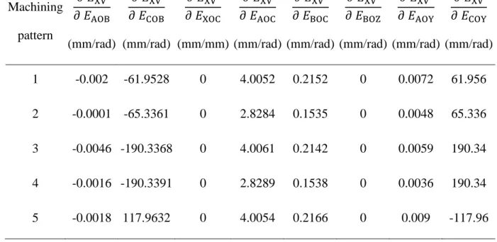
Table 4-2 The sensitivity of the mismatch depth in the x direction ( ) to the link errors ... 63
Table 4-3 The sensitivity of the mismatch depth in the z direction ( ) to the link errors ... 64
Table 4-4 Measurement results using touch trigger probe ... 67
Table 4-5 Measurement results using touch trigger probe ... 67
Table 5-1 Filtration matrix for common machining processes illustrated in Figure 5-1 ... 77
Table 5-2 Machining conditions for each feature ... 86
Table 5-3 Compensability ratio and required Δaxis at critical points in curve slot machining ... 91
Table 5-4 Comparison of the predicted volumetric error before and after compensation at critical points in curve slot machining ... 91
Table 5-5 Comparison of circularity errors for the holes ... 92
Table 5-7 Residual analysis of the cone frustum measurement ... 94 Table 5-8 Residual analysis of the curve sidewall measurement ... 95 Table 5-9 Residual analysis of the curve depth measurement ... 95
LIST OF FIGURES
Figure 1-1 a) Schematic of a bridge-type machine b) roll error of the X-table [Hocken, 1980] ... 7
Figure 1-2 Machine error analysis according to causality principle [Ekinci et al., 2007] ... 10
Figure 1-3 Error motions of a horizontal Z-axis [ISO230-1, 2012] ... 11
Figure 1-4 Error motions of a rotary C-axis [ISO230-7, 2006] ... 12
Figure 1-5 Link errors of a linear axis, Z [ISO230-1, 2012] ... 13
Figure 1-6 Link errors of a rotary axis, C [ISO230-1, 2012] ... 14
Figure 1-7 A five-axis machine tool configuration; 1) rotary C-axis 2) X-axis 3) bed 4) Y-axis 5) column 6) Z-axis 7) yoke 8) A-axis 9) Spindle [ISO230-1, 2012] ... 16
Figure 1-8 Laser interferometer for the measurement of Y-axis positioning error [Schwenke et al., 2008] ... 19
Figure 1-9 Compensation by shifting the origins of machine axes [Ni, 1997] ... 22
Figure 1-10 Error elimination categorization ... 26
Figure 2-1 Thesis organization ... 29
Figure 3-1 Five-axis machine tool (WCBXFZYSt) as a kinematic chain ... 33
Figure 3-2 Volumetric error ... 35
Figure 3-3 Gauss-Newton method for iteration ... 38
Figure 3-4 Error compensation strategy ... 39
Figure 3-5 Top view of the machine tool, BC cross-axis distance error (XOC) causes a mismatch on the part when the same point is reached by the tool using two different rotary axes indexations. ... 40
Figure 3-6 Test steps and machined slots according to Table 3-1 ... 42
Figure 3-7 Machining setup ... 42
Figure 3-8 Volumetric error vector projected in the foundation frame, calculated at arbitrary working points and at the test point on the machined slot, magnified 200X. ... 46
Figure 3-9 Machined slots for original and ephemeral G-code programs ... 46
Figure 4-1 Five-axis machine tool (WCBXFZYSt) as a kinematic chain ... 53
Figure 4-2 Depth mismatch between two halves of the machined slot ... 54
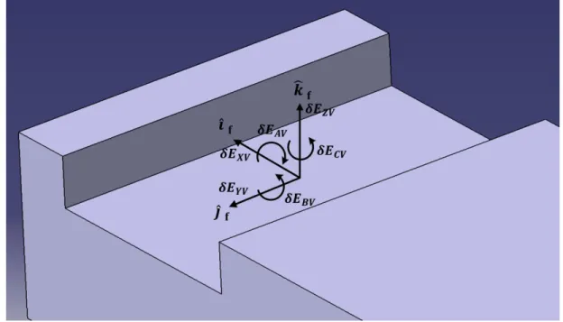
Figure 4-3 Coordinate system and error components on the machined slot ... 56
Figure 4-4 Reference (R), uncompensated (U) and compensated (C) machined slots in each pattern ... 57
Figure 4-5 Proposed patterns for machining the slots ... 59
Figure 4-6 Workpiece with pre-machined planes ... 61
Figure 4-7 Numerical solid model of the nominal machined workpiece ... 61
Figure 4-8 Machined workpiece on the machine table ... 62
Figure 4-9 Probing the machined surfaces to acquire the points coordinates in each half slot ... 64
Figure 4-10 Probing on bottom surface and side surface of the three machined slots of each pattern ... 66
Figure 4-11 On-machine measurement of the mismatches using a Renishaw MP700 touch trigger probe ... 66
Figure 4-12 Mismatch depth comparison in x direction for three slots of each pattern ... 69
Figure 4-13 Mismatch depth comparison in y direction for three slots of each pattern ... 69
Figure 5-1 Relevant components of the volumetric error in common machining processes a) face milling b) hole drilling c) slot milling d) flank milling a conical surface ... 76
Figure 5-2 Five-axis machine tool with the topology WCBXFZYt and and a pure angular error in the tool frame ... 80
Figure 5-3 Changes of with B-axis position ... 82
Figure 5-4 Changes of with B-axis position ... 82
Figure 5-5 Relevant and compensable errors ... 83
Figure 5-7 Machining of a cone frustum ... 85 Figure 5-8 Original G-code for machining the cone frustum ... 87 Figure 5-9 a) compensated G-code b) optimized compensated G-code for machining the cone
frustum ... 87 Figure 5-10 Compensability ratio at working points of the cone frustum machining trajectory ... 88 Figure 5-11 Compensability ratio at working points of the curve slot machining trajectory ... 88 Figure 5-12 Required a) linear b) rotary axes movement for regular and optimized compensation
of cone frustum machining ... 89 Figure 5-13 Required a) linear b) rotary axes movement for regular and optimized compensation
of curve machining ... 89 Figure 5-14 Best fit residuals for the flat surface, magnified 2000X; a) uncompensated, b) regular
compensated and c) optimized compensated plane ... 93 Figure 5-15 Best fit residuals for the cone surface, magnified 1000X; a) uncompensated, b)
regular compensated and c) optimized compensated cone ... 94 Figure 5-16 Best fit residuals for the curve sidewall, magnified 1000X; a) uncompensated, b)
regular compensated and c) optimized compensated slot ... 96 Figure 5-17 Best fit residuals for the curve depth, magnified 1500X; a) uncompensated, b)
INTRODUCTION
With the burgeoning demand for machined parts with complicated shapes and high accuracy, as in the aerospace industry, the use of axis machine tools has been increasing. Applying five-axis machining, the cutting tool can be orientated relative to the part so that shorter machining time, fewer setups, jigs and fixture are required. However, the complex structure of these machines due to the presence of two rotary axes compared to three-axis ones, may cause further volumetric inaccuracy of the tool tip position.
In recent decades, computer numerically control (CNC) of machine tools provided more flexibility and productivity and reduced manual work and operator-related error sources. Machine tools manufacturers’ goal is to minimize the possible error sources when designing, manufacturing and assembling machines to improve the quality of their production and stay competitive. However, reaching to higher levels of accuracy leads to exponentially rising costs. Thus, error prediction and compensation is a worthwhile approach for accuracy enhancement. Machined part dimensions and tolerances, particularly in the aerospace industry, are consistently controlled according to drawing tolerance. The dimensional imperfections of the machined part may come from machine errors like geometric errors of machine joints and components, thermal and cutting force induced errors and so on. The geometric error is a significant one that adversely influences the overall accuracy and cause unwanted deviations of tool location called "volumetric error". Prediction and compensation of the volumetric error in multi-axis machine tools have been the subjects of much research in recent decades.
Problem definition
To compensate the volumetric error in a machine tool, a precise model of geometric and kinematic parameters is required. A general and common understanding of the volumetric error which can be quantified using a mathematical formulation is a perquisite to reach an effective compensation. Once error compensation is implemented, its validation and optimization are also sought.
In addition, the machine structure (topology), the feature to be machined, the machining process and also tool geometry are effective factors in compensation strategy selection, validation and optimization. There is a lack of knowledge about the relationship between the compensation
scheme and the above-mentioned factors. In the present thesis, strategies and techniques are proposed to answer following the main research question:
How to compensate the relevant and compensable volumetric error in five-axis machine tools?
This can be detailed in the form of below questions:
How to calculate and predict the components of volumetric error in a five-axis machine? Is it possible to predict the volumetric error using the original G-code and then
compensate errors through G-code modification?
How to validate the compensation effectiveness using on-machine measurement (OMM) without an external measurement device?
Do all volumetric error components require compensation?
Is it possible to compensate all components of the volumetric error by changing original axes commands?
Objectives
To effectively compensate the volumetric error in a five-axis machine tool, these specific objectives are defined:
1. Develop an exact mathematical formulation to predict the volumetric error vector that relies solely on original axes positions and the machine error parameters.
2. Propose a fast and easy method for validation of error compensation effectiveness in machine tools without using CMM.
3. Reduce the demand on volumetric error compensation by considering the tool geometry and the feature to be machined.
4. Quantify the machine capability to compensate all volumetric error components by G-code adjustment.
Hypotheses
Volumetric error twist in a five-axis machine tool can be predicted using a general modeling formulation, original G-code, machine tool error parameters and then compensated by minute adjustments in original commands of the machine axes.
The effectiveness of a compensation strategy can be validated using OMM and without need for an external measurement device such as CMM.
Minimal and effective modifications in axes positions can be calculated and implemented in an optimized compensation strategy in which only relevant and compensable error components are attempted to be compensated.
Assumptions
The assumptions considered in this research are as follow:
Rigid body kinematics: the mathematical model of the machine tool is developed assuming that the machine joints and structure are rigid. Therefore, the error components of each joint are not influenced by the movement of other;
estimated values for machine joints errors are known as input of the compensation function and also they remain constant after estimation and before machining tests are done;
the machine tool is supposed to be able to accurately track the programmed commands and uploaded to the CNC controller;
machine error values are sufficiently small to assume small, but not negligible, angular errors and approximation of the equations in the first article;
nominal dimensions and location coordinate of the feature to be machined and tool geometry are known for the third paper when studying relevance of the error components.
CHAPTER 1
THEORY AND LITERATURE REVIEW
Basically, for the volumetric error compensation in machine tools, three steps should be taken into consideration; 1) Modeling of the machine tool and its errors, 2) Error measurement and identification, 3) Implementation of a compensation strategy. In this chapter, general definitions and concepts of error sources in multi-axis machine tools, as a perquisite for machine modeling and compensation, are presented. This is followed by an introduction about machine error measurement and identification techniques and then error elimination (reduction) strategies. Since error elimination or compensation is the main subject of the work, this will be explained in details in this chapter and the next chapters in the form of research articles.
1.1 Error sources and classifications
Error is “the difference between the actual response of a machine to a command issued according to the accepted protocol of that machine's operation and the response to that command anticipated by that protocol” [Hocken, 1980]. Various error sources may lead to overall machine inaccuracy and imperfections in machined part dimensions and geometry. Generally, machine errors are classified into two categories namely quasi-static errors and dynamic errors. Quasi-static errors are associated with the structure of the machine tool itself and do not depend on the particular operating conditions of the machine. The sources of these errors include geometric errors, errors due to the dead weight of the machine components and those due to thermally induced strains in the machine structure. Such errors slowly vary in time and accounted about seventy percent of the total error of machine tools. Thus quasi-static errors are a major error focus in error compensation research. On the other hand, dynamic errors are related to the dynamic behavior of the machine and usually depend on machining conditions during cutting operation such as spindle error motions, vibration of the machine structure, tool deflection and servo control and contouring errors [Hocken, 1980].
In this section, brief introductions to some of these errors are separately presented.
1.1.1 Thermal errors
Thermal errors or temperature induced errors are due to internal or external heat/cold sources. In addition to quasi-static errors due to thermally induced strains in the machine structure, dynamic behavior of the machine also produces thermal error. The movement of machine elements and
continuous running of motors and pumps during the machining process generate considerable heat. Significant expansion coefficients and expansion coefficient differences result in thermal distortion of machine elements [Schwenke et al., 2008]. Thermal factors contribute 40-70% of total dimensional and shape errors of the machined part. Six sources of thermal deformation are identified; 1) heat from the cutting process, 2) heat generated by the machine, 3) heating or cooling provided by cooling system, 4) environmental temperature, 5) effect of people, 6) thermal memory from previous environments [Bryan, 1990]. The heat transferring across the machine structure depends on the distribution of contact pressure along each joint and can be described based on the theory of thermo-elastic behavior [Attia et al., 1979]. A certain percentage of the total power of the machine is converted to thermal energy because of the frictional resistance exists in moving elements. Continuous movements of bearings, gears, hydraulic oil, drives, clutches, motors, pumps and guideways during machining operations cause temperatures to rise in the machine tool. Spindle growth, thermal expansion of the ball screws and thermal distortion of the column are some of its consequences that may influence the relative position and orientation of the tool. Additionally, heat generated by the shearing action during cutting (some of which is transferred to the deformed chip) should be considered as an important heat source [Ramesh et al., 2000].
The thermal errors can be categorized in two groups. The first group includes the position independents thermal errors (PITE) which vary with temperature but not the axis position. These errors don't depend on the joints positions and mostly affect the machine offsets. The second group is function of both axis position and temperature. These are called position dependent thermal errors (PDTE) and usually produce linear positioning errors [Allen et al., 1997].
The linear and time-varying nature of the thermally induced errors that come from non-uniform temperature distribution in machine structures and also the complexity of heat transfer mechanism makes it complicated to model and predict the thermal errors [Mou, 1997]. But, thermal errors cannot be neglected in machine tool accuracy improvement; particularly when a “real-time” compensation strategy is implemented. Thermal effect of heat produced during machining is possible to be detected using temperature sensors and considering the thermal errors in machine model for error compensation purpose. Reduction of external and internal heat sources, control of heat flow, usage of high volume of coolant, redesign the machine tool and
making machine components less sensitive to the heat flow are some proposed strategies to minimize thermal errors [Ramesh et al., 2000].
1.1.2 Load induced errors
The major sources of load induced errors can be divided into three categories, i.e. 1) strain resulting from the machine tool assembling, 2) strain resulting from the dead weight of the machine elements, 3) strain resulting from workpiece weight [Hocken, 1980].
1.1.2.1 Machine tool materials and assembling
The instability of the materials may result in geometric distortion in machine structure such as long-term dimensional length changes. Slow relaxation of metallurgical stress (e.g., iron casting or steel weldments) is the main reason of such instabilities. However, this error source can be minimized through stress-relieving methods such as vibration at liquid-metal solidification stage, vibration in solid state, commercial stress-relief annealing, weathering, etc. Great stress relief is achievable in good quality iron casting or steel weldments by means of long-cycle stress relieving process. Another error source is due to machine foundation and its mounting. Using a minimum but efficient number of physical constraints to constrain the machine body (e.g. kinematic mounting) provides the highest accuracy. This approach is mostly applicable for small and medium-size machine tools for which the foundation problems can be eliminated. For large machine tools, the properties of bedplate, foundation, and soil structure, static deformation and damping behavior of foundation and also, its long-term dimensional stability are of importance to reduce the error sources [Hocken, 1980].
1.1.2.2 Self-loading forces
Due to the finite stiffness of the load-bearing elements, static deformations may occur especially in large machine tools in which larger and heavier components are used and their displacement may cause deformations out of allowed limits. For instance, a vertical straightness and a pitch error motion may occur in straight guideways due to the weight of the moving slide. This is called " quasi-rigid behavior" [Schwenke et al., 2008]. Sometimes, the motion of one component affects the motion of another one (cross-coupling).For example, in the bridge-type machine tool shown in Figure 1-1a, a roll error (rotation around X-axis) may occur as a result of the Y
carriage movement across the table. Figure 1-1b clearly illustrates that the changes in Y position of the cross carriage mounted on the bridge is affecting the positioning error of the X table.
Figure 1-1 a) Schematic of a bridge-type machine b) roll error of the X-table [Hocken, 1980]
1.1.3 Dynamic force induced errors and vibrations
The presence of significant dynamic forces during cutting processes influences the overall accuracy by excessively deforming the tool and work piece or deformation of machine tool structure. Depending on the stiffness of the machine structure, its accuracy is affected by such forces.
Vibration of the machine tool during cutting operations is another source of volumetric error especially in milling processes in which the tool experiences periodic forced vibration. The magnitude and the phase of these vibrations depend on several factors such as the spindle speed and the number of teeth on the cutter, cutting coefficients of the tool/workpiece system, the radial and axial depths of cut, the feed per tooth and the cutter helix angle [Schmitz et al., 2008]. Vibration induced errors are not easily compensable due to very often unknown amplitude and the phase angle of the vibration frequencies. The resultant relative motions between tool and workpiece have detrimental effects on the surface roughness as well as tool wear. Sometimes vibrations come from external sources through foundation, bearing defects, interrupted cuts, etc. This type of vibration is named forced vibrations. On the other hand, self-excited vibration which
is associated with machine vibrations in one or several natural frequencies while there is no external noise or factor [Hocken, 1980]. Finally, in the case of high speed machining (high feed rate and velocity), forces caused by acceleration and decelerations of machine parts vary during machining process and may result in significant errors [Cano et al., 2008].
Tool deflection occurs due to machining forces and produces surface location errors. In the case of milling, the tooth either deflects towards the surface in up-milling thus causing an over cut form error, or deflects away from the surface in down milling causing an undercut form error. The periodic force at the contact point of tool and feature leads to vibration as Schmitz et.al [Schmitz et al., 1999] investigated the effect of spindle speed (tooth passing frequency) on tool deflection in high speed machining and found both system natural frequency and flexibility as the important factors to choose the depth of cut for a stable operation.
Some researchers have neglected the effect of cutting force induced errors considering that for the finishing process, the cutting forces are too small to influence the overall accuracy. However, in cases of machining some materials like hardened steel to final form (without finishing operation), large forces may be the source of considerable errors and this has to be considered in an overall compensation process [Ramesh et al., 2000]. Errors induced by cutting forces can be particularly dominant also in turning thin workpieces (where a significant elastic deflection occurs in workpiece) or in boring small diameter holes (where tool is subject to have a significant deflection) [Li, 2001].
1.1.4 Fixture dependent errors
A fixture is an element that holds the workpiece on the machine table during machining. Errors in fixture and setup are related to geometric inaccuracies or misalignments of the locating element. Furthermore, if the workpiece is not fixed well or if the fixture is too compliant, its deformation or displacement may become a significant source of error. Therefore, the appropriate fixture elements and locators, clamping sequence, clamping intensity and the contact area of workpiece are of importance to avoid the fixture dependent geometric errors [Hockenberger, 1994; De Meter et al., 1997; Ramesh et al., 2000].
1.1.5 Contouring and servo errors
After modeling the part to be machined in a manufacturing process, usually a computer-aided machining software is used to generate a desired tool path for machining. Due to interpolation and discretization methods applied for tool path generation of complex shape parts, there may be some differences between the generated tool path and the numerical model of the part. Approximations occur in the inverse kinematic transformation during the post-processing phase are also, should be considered as a source of error in machine tool. Reversal spike and servo mismatch are examples of control system and servo setting error sources. Accurate path tracking for contouring is not always possible due to the loss of joint coordination or CNC controllers’ limitations especially during high speed motions. Each machine axis may have follow-up errors, influencing the overall accuracy [Lavernhe et al., 2008; Andolfatto et al., 2011]. In other words, unavoidable tracking imperfection between the commanded and actual positions may occur due to the servo controller dynamics that result in contouring errors. The contour error can be defined as the normal distance, of the actual tool tip, from the desired (reference) tool path while tool
orientation contour error can be defined as the normal angular deviation of the tool axis from the
desired orientation trajectory [Koren, 1983]. Modeling, evaluation and compensation of contouring errors are studied in some researches [Kwon, 1996; Sencer et al., 2009].
1.1.6 Geometric errors
Machine tool accuracy is directly affected by manufacturing defects, surface straightness and roughness of the machine components and bearing pre-loads. Geometric errors include firstly, the straightness error of the guideways upon which a machine axis carriage moves and secondly, the link geometric errors which may result from shape and assembly errors of the machine structural components.
1.2 Description of the machine errors
According to causality principle, Ekinci et al. [Ekinci et al., 2007] proposed a hierarchal classification of machine errors. As shown in Figure 1-2., geometric errors of the guideways directly lead to kinematic errors in moving joints which would be called “error motions”. The second group of the errors considered in the kinematic chain model is called “link geometric errors”.
Figure 1-2 Machine error analysis according to causality principle [Ekinci et al., 2007] The error motions are position dependent geometric parameters (PDGEPs) while the link errors are called position independent geometric parameters (PIGEPs). Link errors are basically associated with misalignment of a structural component and its deviation from the nominal position and orientation in the machine coordinate system such as out of squareness, angular offset and rotary axes separation errors [Abbaszadeh-Mir et al., 2002]:
In next section, all possible motion errors and link errors for multi-axis machine tools are described based on the standard ISO 230. Other common notations for such errors are compared in [Ibaraki et al., 2012].
1.2.1 Error motions
As shown in Figure 1-3, a linear axis (Z-axis for example) could have six motion errors when it moves. These errors are listed in Table 1-1 where the notation is based on ISO 230-1[ISO230-1, 2012]. If, the behavior of the machine is assumed as a rigid body, such errors depend only on the
nominal movement of the axis of concern and so, the location of the other axes does not affect them [Schwenke et al., 2008].
Figure 1-3 Error motions of a horizontal Z-axis [ISO230-1, 2012]
Table 1-1 Error motions of a horizontal Z-axis, notation is according to ISO 230-1
Error description Error symbol
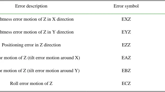
Straightness error motion of Z in X direction EXZ Straightness error motion of Z in Y direction EYZ
Positioning error in Z direction EZZ
Pitch error motion of Z (tilt error motion around X) EAZ Yaw error motion of Z (tilt error motion around Y) EBZ
The same possible errors may exist for a nominal rotational movement (for example C-axis) as shown in Figure 1-4 and listed in Table 1-2.
Figure 1-4 Error motions of a rotary C-axis [ISO230-7, 2006]
Table 1-2 Error motions of a rotary C-axis, notation is according to ISO 230-1
Error description Error symbol
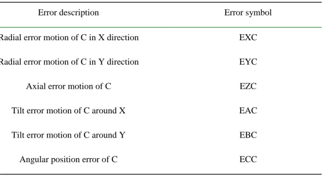
Radial error motion of C in X direction EXC
Radial error motion of C in Y direction EYC
Axial error motion of C EZC
Tilt error motion of C around X EAC
Tilt error motion of C around Y EBC
1.2.2 Link errors
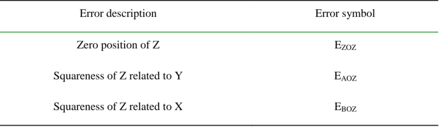
To define the link errors relative to the reference coordinate, generally a “reference straight line (average location and orientation) is assumed as the nominal axis (linear or rotational) according to ISO 230-1. A linear motion axis can be defined as a vector with a zero position on the vector. Thus, there are only two squareness errors and the zero position error for it as shown in Figure 1-5 and Table 1-3.
Figure 1-5 Link errors of a linear axis, Z [ISO230-1, 2012]
Table 1-3 Link errors of a linear Z-axis, notation is according to ISO 230-1
Error description Error symbol
Zero position of Z EZOZ
Squareness of Z related to Y EAOZ
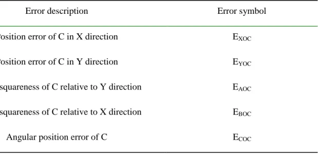
A rotary axis has also two translational errors in addition to the ones of a linear axis as shown in Figure 1-6 and Table 1-4.
Figure 1-6 Link errors of a rotary axis, C [ISO230-1, 2012]
Table 1-4 Link errors of a rotary C-axis, notation is according to ISO 230-1
Error description Error symbol
Position error of C in X direction EXOC
Position error of C in Y direction EYOC
Out-of-squareness of C relative to Y direction EAOC
Out-of-squareness of C relative to X direction EBOC
The total number of errors of a particular machine tool depends on the number of axes. In three-axis machine tools, there are only three prismatic joints whereas, a five three-axis machine tool is a kinematic chain made of three prismatic and two rotary axes and can be in various arrangement of sequential manners. Everett et al. [Everett et al., 1988], proposed Eq. 1-1 to determine N, the minimum number of fixed value parameters required to define a serial kinematic chain, the robot base frame and end effector frame (regardless of the modeling scheme);
(1-1)
where R is the number of rotary axes and P is the number of prismatic axes. Thus, N=20 in five-axis machines. If six parameters among of these 20 parameters are assumed to define the tool frame location and another six to locate the work piece relative to the work piece axis branch, then, only eight link error parameters are remained for the machine internal structure. If the spindle axis and its five error parameters (the rotational error around spindle axis is not accounted as an error) are also considered, a total of 13 link errors are required for error modeling of the five axis machine tool [Zargarbashi et al., 2009].
Based on Abbaszadeh-Mir research [Abbaszadeh-Mir et al., 2002], potentially 42 PIGEPs or link errors are considered for prediction of tool location error respect to the feature in five-axis machine tools; six PIGEPs per axis, six parameters to describe the pose error (positioning and orienting error) of the work piece and an additional six error parameters for the pose of the tool frame in the spindle. Using mathematical analysis of the sensitivity Jacobian matrix, its rank and singular value decomposition (SVD), eight independent error parameters can be determined as the minimum but sufficient set of link error parameters required for estimation of the volumetric error. This is also mentioned in ISO 230-1 (Annex A). In this standard, first, position and orientation error parameters for each axis of a five-axis machine tool (Figure 1-7) are presented. If the coordinate system is defined using the linear axes of motion of the machine, a set of minimum number of error parameter to fully characterize the five-axis machine tool can be extracted as seen in Table 1-5. Note that the possible errors of the spindle axis are not shown in this table [ISO230-1, 2012].
Figure 1-7 A five-axis machine tool configuration; 1) rotary C-axis 2) X-axis 3) bed 4) Y-axis 5) column 6) Z-axis 7) yoke 8) A-axis 9) Spindle [ISO230-1, 2012]
Table 1-5 Minimum number of error parameter to fully characterize a five-axis machine tool
C-axis X-axis Y-axis Z-axis A-axis
0 (0) - - -
0 - (0) - EYOA
- - - (0) 0
EAOC - 0 EAOZ (0)
EBOC 0 - EBOZ EBOA
1.2.3 Volumetric error
The term “volumetric error” refers to the resulting error in position and orientation of the machine tool end effector (tool or stylus tip) related to the workpiece or feature to be machined or measured. The term “volumetric accuracy” for three-axis machine is defined as” the maximum range of relative deviations between actual and ideal position in X-, Y-, Z-axis directions and the maximum range of orientation deviations for A-, B- and C-axis directions for X-, Y- and Z-axis motions in the volume concerned [ISO230-1, 2012]. This definition is valid for the rotary axes accuracy in five-axis machine tools too. This error is defined in the working volume of the machine and can be measured using calibrated artifacts or telescoping ball-bar. In chapter three, a general mathematical formulation for volumetric error and also a graphical representations of that will be explained.
1.3 Machine tool modeling
Most machine tools are serial kinematic chain made of successive joints and moving components to provide a desired relative location between cutter tool and the feature to be machined. The common modeling approaches are as follows;
Rigid body kinematics is one of the most widely used techniques for simulation and modeling of the machine tools. Based on rigid body kinematics, machine tool axes and links are connected to each other like a chain but error motions of each axis are not influenced by other axes position. The direct kinematic model can be built using homogenous transformation matrices (HTMs) [Roberts, 1966] and accommodating both link and motion error modeling. Srivastava [Srivastava et al., 1995] used this approach to model geometric and thermal errors in a five-axis machine tools. This modeling approach is used to model the machine tool in the present research as explained in details in chapter three (first article).
Non-rigid body assumption may be applied where a heavy movable slide in a large size machine, for instance, produces deformations in the guideways of other slides. Chen et al. [Chen et al., 1992] compared two approaches, i.e. off-line multidimensional fitting and on-line identification to measure the non-rigid body kinematic effect using a laser
interferometer and then compensated it by compensation signals through digital I/O board.
D-H modeling [Denavit, 1955]; using D-H modeling, Mahbubur et al. [Mahbubur et al., 1997] proposed a compensation strategy in which the nominal values of the rotary axes are derived from CL-data and then applied for correcting the tool path within the post-processor before generating the G-code. This modeling approach is mostly used to model the robots and not machine tools. This is due to the rules imposed in this method for the definition of the local reference frames.
Product of exponential (POE) method is widely used in robotic and recently in machine tools. It represents the kinematics of an open-chain mechanism as the product of exponentials of twists. Using POE method, the problem of determining the joint angle given the end-effector location (inverse kinematic) can be solved compared to D-H modeling. Furthermore, the manipulator Jacobian and its singularities can be easily characterized. [Murray et al., 1994].
1.4 Error measurement and identification
1.4.1 Direct and indirect measurement
Several measurement instruments and techniques are applied to detect the geometric errors of the machine tool. The most suitable measuring method depends on the machine geometry and the errors to be measured or identified. In "direct" measurement methods, a specific geometric error of only one axis is measured and there is no need to simultaneously move other axes. Direct measurements can be divided into three subgroups [Sartori et al., 1995; Schwenke et al., 2008];
1. The material-based methods wherein standard artifacts such as straightedges, line scales or step gages and even multidimensional artifacts like ball plates are applied.
2. The laser-based methods which use laser light wavelength as a reference; Environmental factors like temperature and pressure have a relatively small effect on the laser wavelength characteristics but should be taken into consideration for calibration purposes. Yielding a high accuracy on short- and long-machine axes, the laser interferometer is commonly used for measurement of the positioning errors as shown in Figure 1-8.
3. The gravity-based method wherein local gravity of the earth is used to define the metrological reference to measure some errors such as angular errors around horizontal axes.
Figure 1-8 Laser interferometer for the measurement of Y-axis positioning error [Schwenke et al., 2008]
In contrast, "indirect" measurement techniques focus on superposed errors and thus, multi-axis motions are required. Either calibrated, partially calibrated or un-calibrated artifacts may be used in indirect methods. Contour measurement, multi-lateration measurement and chase-the-ball measurement are some examples of indirect measurement approaches. [Schwenke et al., 2008]. One of the most common indirect methods is the circular test using a ball bar as presented in ISO 230-4 [ISO230-4, 2005]. This method was established by Bryan [Bryan, 1982] and is applicable to check of contouring accuracy, backlash error and also the error motions of two orthogonal linear axes in machine tools. Other developed artifacts and measurement approaches are still the subject of much researches [Lei et al., 2002; Weikert, 2004; Zargarbashi et al., 2009; Erkan et al., 2011].
1.4.2 Error identification
The machine error to be identified must have a significant effect on the measurement results in order to its influence to be separated from any combination of other parameters. In other words, if, a geometric error parameter does not have a distinguished effect on the measurement result, its identification may be impossible. Error identification is done using analytical or best fit methods.
Regarding the measurement method applied, an appropriate identification approach is used. For example, the errors measured using calibrated artifacts or self-calibrated methods could be identified by analytical methods. While best fit methods are usually used in cases of multi-lateration or chase-the-ball measurement methods [Schwenke et al., 2008]. Another categorization for error identification approaches was reported by Lo [Lo, 1994], i.e. 1) grid calibration method 2) error synthesis method 3) designed artifact method 4) metrology frame method 5) finite element method. He found the error synthesis model as the only efficient method to correct the overall quasi-static error in his research on a four-axis turning center. In addition, an adaptive error identification method was developed [Mou et al., 1995] in which inverse kinematic were used to characterize the individual effect of machine error parameters on machined part geometric errors.
1.5 Error elimination and its categorizations
The efforts for accuracy improvement for machine tools are categorized in two main groups; "Error avoidance" and "error compensation".
1.5.1 Error avoidance
In "error avoidance", the source of the error or its effect is eliminated through refinement of the machine design or its environment. The machine accuracy is improved during both designing and manufacturing steps. Precise components, high stiffness, and low thermal distortion will result in machine accuracy enhancement. However, this approach basically needs high degree of investment especially to reach as accuracy beyond a certain level. As an example, to avoid the thermal induced errors in machine tools, three strategy are proposed [Ni, 1997]:
a) heat source reduction; control the environmental conditions through heat exchangers or enclosing the machine tool in temperature-controlled boxes.
b) heat flow control through passive control (such as blocking the heat flow using insulation pads) or active control (modifying the thermal-induced deformations of machine tool structure by using an external heat source to minimize the machine warm-up time etc.) c) thermally robust structural design; that reduces the sensitivity of machine structure to
1.5.2 Error compensation
The second approach is "error compensation" in which no attempt is made to avoid the error and involves lower costs compared to the former. In this approach, the errors in the machine are measured and then suitably compensated. In the literature, the strategy reported by Koliskor [Koliskor, 1971] based on the results of post-process inspection and also the software-based method developed by Donmez et al. [Donmez et al., 1986] for geometric error correction are two early researches on error compensation. The strategies for error compensation can be generally categorized as follow:
1.5.2.1 Real-time compensation and off-line compensation
If the machining process and measurement is repeatable enough, a “pre-calibrated” error compensation can be applied. Errors are measured after the machining process and used to subsequently change or calibrate the process (off-line). This method is suitable especially for cases involving with mass productions. The second and more accurate method is named "real-time active error compensation" (or “dynamic compensation” as it is named in [Ramesh et al., 2000]) wherein the process is altered or calibrated based on the error measurement results during the same operation. However, this is more expensive and time consuming compared to the former [Hocken, 1980].
Two real-time techniques are proposed as follow:
Feedback interception method in which feedback signals from the servo loop are intercepted by a computer. The computer calculates the volumetric error and modifies the feedback signals before embedding back to the controller and this, leads to adjustment of the slide position [Yee et al., 1990]. Although, no modification in controller software is required, the electronic devices used for insertion of the quadrature signals in this technique need extreme caution to prevent inserted signals interfering with the machine tool error controls.
Origin-shift method in which the computer sends compensation signals after calculating the volumetric error and without interception of the feedback signal from servo loop. This results in shifting the reference origins of the control system through an I/O interface as shown in Figure 1-9 [J.S. Chen, 1993].
Figure 1-9 Compensation by shifting the origins of machine axes [Ni, 1997]
In real-time compensation usually the information on thermal-induced errors and force-induced errors are acquired using sensors mounted on the machine and so, a synthesis model of all positioning, thermal and force errors is used [Lo, 1994; Spaan, 1995]. Although, both systematic and random errors can be corrected, there are some difficulties in this approach. Firstly, finding the optimal location of the sensors (especially thermocouples) to be mounted is not easy and usually needs statistical analysis and several empirical (trial-and-error) processes. Secondly, characterization of the machine thermal behavior is time consuming since a considerable time is needed for machine to reach the thermal steady state and then to cool down to its original state. Robustness of the error model when modeling the thermal errors depends on several factors such as sensors mounting location, sudden change in the coolant or environmental temperature etc. [Ni, 1997].
1.5.2.2 Software (numerical) compensation and hardware compensation
Another categorization for the compensation techniques could be assumed; 1) hardware error compensation (similar to the error avoidance conceptm involves modifications in machine tool hardware and physical components and so, applicable only when errors are larger than a defined
range and 2) software error compensation. Hocken [Hocken, 1993] defines the term software correction as follows: “The use of per-process data, a machine model and indirect sensing of process parameters relevant to that model, in order to provide data to control system for the correction of a nominal tool position with respect to a nominal part during the machining process or measuring using the actuators normally supplied with the machine.” Software compensation is also called “numerical compensation” in some references.
For numerical compensation, the quantified information of machine errors through measurement methods is required. The compensation will be effective if the machining conditions and errors are time invariant and also have high repeatability. An absolute coordinate system is also required. Numerical compensation could maintain accuracy over the machine life time even when its geometry changes due to aging, wear, foundation stabilization, environment thermal condition, etc. However, the required motions for error compensation in the functional orientation in five-axis machine tools is not always available to the CNC and it may leads to highly accelerated motions of other axes. The thermal conditions of the machine and the object used for its calibration affect the numerical compensation results and should be considered as one of the limitations [ISO/TR16907, 2015].
Most modern industrial controllers provide useful tools to compensate specific geometric errors such as positioning errors of linear and rotary axes, backlash error, straightness error and some thermal induced errors. As discussed in ISO/TR 16907 [ISO/TR16907, 2015] and also [Sartori et al., 1995], there are four ways to store the error information (obtained from measurement) into the CNC controller;
Error lattice; the error magnitudes are stored at points spread evenly in a working volume and used to directly compensate only translational deviations at those spatial points. Such error lattices are applicable only when the tool offset is fixed.
Look-up tables; assuming positioning errors as a function of axis position, such tables contain nominal position and direction of the axis motion and the corresponding error value (which is a correction value to cancel the error effect). CNC controller may apply linear interpolation for intermediate points.
Coefficient table; the coefficients of polynomials used for analytical error modeling are stored and employed for error compensation at working points.
Spatial error grid tables; in which user is required to input translational and angular error values at all grid points of each linear or rotary axis. A model based software may calculate the spatial error grid both on modeled or un-modeled error motion of the machine tool. An example of such spatial error grid tables is shown in Table 1-6.
Table 1-6 A spatial error grid for rotary axes [ISO/TR16907, 2015] Point
No.
Sample points Compensation value (error value)
A (or B)-axis C-axis (mm) (mm) (mm) (°) (°) (°) 1 0 0 0 0 0 0 0 0 2 0 5 0.001 -0.001 0.001 0 0 0.001 3 0 10 0.002 -0.002 0 0.002 -0.001 0.002 … … … …
Correction of erroneous tool path prior to the inverse kinematic conversion to G-code is another software compensation strategy widely used in the literature. Uddin et al. [Uddin et al., 2009] employed this strategy in five-axis machining of a cone frustum as the case study (based on standard NAS979). In a similar strategy, a recursive compensation method was applied by Khan et al. [Khan et al., 2011] in which the nominal tool path is obtained from CAD/CAM software and the actual path is calculated through kinematic equations considering error information. Then, the correction vector is computed from the difference between the actual and nominal paths and is used to correct the actual path until an assigned tolerance limit is satisfied.
Some research focused on compensation of both translational and angular errors in presence of rotary axes in machine tools. As a recent case, Lei and Hsu [Lei et al., 2003] assumed a linear relation between differential changes in machine joint coordinates and the workpiece Cartesian coordinates and used a nominal machine Jacobian matrix to calculate the correction vector and then conduct real-time compensation. Due to some limitations of the proposed method, such as singular points of the machine, they, later applied a two-step process (decouple method) assuming that the motion of only rotary axes can compensate the tool orientation error. This
method first compensates the volumetric errors relevant to rotary axes and then, linear ones in real time [Hsu et al., 2007].
Khan et al. [Khan et al., 2011] grouped numerical (software) compensation techniques into four main classes as shown in Figure 1-10;
1. Additional embedded software module wherein the position signals are modified in an additional software module based on machine error information. This module could be either inside of the controller or get connected to it using I/O interface.
2. Control parameter modification: it is possible to calibrate some of the controller parameters before executing the NC program. The information of some errors such as pitch error, backlash error, temperature error, etc. can be uploaded in the CNC controller look-up or spatial grid tables. Siemens 840D and Heidenhain iTNC are some examples of controllers equipped with control systems to compensate sagging, lead screw, and even nonlinear behavior errors.
3. Post-processor modification: Post processor applies the cutter location (CL) data and machine geometry information to produce the NC program. If geometric error information is available, a compensated NC code can be produced, in principle.
4. NC program modification: In the cases that machine has a close-structure controller or the post processor does not cater for the all required error information, NC code modification after post processor step could be a strategy for compensation.
CHAPTER 2
ORGANIZATION OF THE WORK
After an introduction to the thesis subject and objectives, the theory and a critical literature review were presented in the first chapter. In this chapter, the general organization of the work and the coherence of articles presented in the thesis are briefly described. Based on the defined objectives for the project, the three presented articles answer these questions, respectively:
1) How to compensate the errors?
2) How to validate the compensation strategy? 3) How to optimize the compensation?
Chapter three includes the first article entitled “volumetric error formulation and mismatch test for five-axis CNC machine compensation using differential kinematics and ephemeral G-code” which is published in the international journal of advanced manufacturing technology. It proposes an off-line strategy for error compensation in which original G-code is modified after the post-processing step and before being uploaded into the controller. First, the axis commands are extracted from the original G-code and used for volumetric error prediction. A general formulation for volumetric error twist is developed that solely relies on the axis commands and machine error parameters. Assuming a local linearization of the actual erroneous kinematic model in the form of a sensitivity Jacobian matrix, it is possible to mathematically relate the differential changes in volumetric error at the tool tip to small changes of the machine axes positions. Therefore, a correction vector cancelling the effect of the volumetric error is defined and then the required small changes of the machine axes position to produce such a correction vector at the tool tip are calculated. This provides a modified G-code in which the axes commands are adjusted before uploading to the CNC controller. For validation purpose, a new experimental procedure based on a surface mismatch producing machining test is introduced and performed on a HU40T CNC machine. The newly produced code is coined ‘ephemeral G-code’ because it must be regenerated as the machine geometry changes over time.
In the next article (chapter four) entitled “validation of volumetric error compensation for a five-axis machine using surface mismatch producing tests and on-machine touch probing”, published in the International Journal of Machine Tools and Manufacture, the idea of surface mismatch producing test is further developed for more machine axes indexations sets. Seven
series of machining patterns are proposed as a new validation strategy. In each proposed pattern, two-dimensional geometric features are milled, each using two different rotary axes indexation sets. Due to the machine geometric errors, a surface mismatch may appear in each feature that helps to verify the machine volumetric accuracy. The overall accuracy of the machine after implementation of the compensation strategy is checked using a touch probe and OMM (on-machine measurement) immediately after machining. The OMM is accurate enough and does not need to be compensated since the measurement is done in a small volume and using a single linear axis motion and in the same direction for each slot so that most error sources affecting the probing cancel out.
Finally, in the third article which is submitted to the the “CIRP Journal of Manufacturing Science and Technology”, the optimization of the compensation is pursued and two new notions are introduced in five-axis machining. The “relevance” of the error indicates if the final dimension and accuracy of the machined part is affected by an error component or not. The irrelevant components of the volumetric error that have no effect on the machined part accuracy do not require compensation. A filtration matrix is defined for each machining process regarding the tool geometry and the feature to be machined. The second introduced notion is the “error compensability” which refers to the ability of the machine to cancel the effect of volumetric error. Due to the kinematic singularities of the machine tool, it may not be possible to compensate all error components by small adjustments in machine axes positions. In the proposed optimized compensation, first, the irrelevant errors are filtered out in compensation process and their reduction is not sought. Then, the uncompensable parts of the volumetric error are flagged using a compensability ratio and filtered out in the compensation process. As a case study, a designed workpiece containing four common features, i.e. hole, curved slot on a spherical surface, cone frustum and flat surface, is machined using uncompensated, compensated and optimized compensated G-code. This chapter also includes visual presentations and comparison of best fit residuals of the measured features before and after compensation.
Figure 2-1 shows the highlights of the mentioned articles in brief. A general discussion on the three articles is presented in the sixth chapter which is followed by the conclusions and recommendations. The thesis ends by the list of all bibliographical references used in this work.
CHAPTER 3
ARTICLE 1: VOLUMETRIC ERROR FORMULATION
AND MISMATCH TEST FOR FIVE-AXIS CNC MACHINE
COMPENSATION USING DIFFERENTIAL KINEMATICS AND
EPHEMERAL G-CODE
Mehrdad Givi 1 and J.R.R Mayer 1
1
Mechanical Engineering Department, Polytechnique Montréal, P.O. Box 6079, Station Downtown, Montréal (Qc), Canada, H3C 3A7
*Based on the paper published in the International Journal of Advanced Manufacturing Technology: 1-9, 2014
3.1 Abstract
Machine tool kinematic errors directly impact on the accuracy of machined parts. A general volumetric error formulation effectively implementing ISO230-1:2012 definition and an off-line compensation scheme are proposed and partly tested to improve part accuracy on a five-axis CNC machine. Using rigid body kinematics and estimated machine error parameters, the machine position commands contained in a standard G-code are used to calculate the tool erroneous location. The Jacobian, expressing the differential joint space to Cartesian space relationship, is also developed and used to calculate minute joint command modifications so that the effect of inter-axis link errors and intra-axis error motions, for example, can be canceled by making small changes directly to the G-code. Finally, a simple case of a machining sequence producing a surface mismatch in the presence of particular machine deviations is used to illustrate the usefulness of the analytical tools presented. A graphical representation of the volumetric errors assists in understanding the impact of each error source for this particular application. The measurement results are compatible with the predicted volumetric error values and show an accuracy improvement of about 90 % after compensation.
![Figure 1-1 a) Schematic of a bridge-type machine b) roll error of the X-table [Hocken, 1980]](https://thumb-eu.123doks.com/thumbv2/123doknet/2331764.31861/22.918.146.773.182.515/figure-schematic-bridge-type-machine-error-table-hocken.webp)
![Figure 1-7 A five-axis machine tool configuration; 1) rotary C-axis 2) X-axis 3) bed 4) Y-axis 5) column 6) Z-axis 7) yoke 8) A-axis 9) Spindle [ISO230-1, 2012]](https://thumb-eu.123doks.com/thumbv2/123doknet/2331764.31861/31.918.211.704.112.463/figure-machine-tool-configuration-rotary-column-axis-spindle.webp)
![Figure 1-8 Laser interferometer for the measurement of Y-axis positioning error [Schwenke et al., 2008]](https://thumb-eu.123doks.com/thumbv2/123doknet/2331764.31861/34.918.205.712.243.508/figure-laser-interferometer-measurement-axis-positioning-error-schwenke.webp)