HAL Id: tel-01668545
https://pastel.archives-ouvertes.fr/tel-01668545
Submitted on 20 Dec 2017
HAL is a multi-disciplinary open access
archive for the deposit and dissemination of sci-entific research documents, whether they are pub-lished or not. The documents may come from teaching and research institutions in France or abroad, or from public or private research centers.
L’archive ouverte pluridisciplinaire HAL, est destinée au dépôt et à la diffusion de documents scientifiques de niveau recherche, publiés ou non, émanant des établissements d’enseignement et de recherche français ou étrangers, des laboratoires publics ou privés.
superchannel transmission system
Abdelkerim Amari
To cite this version:
Abdelkerim Amari. Nonlinear effects compensation for long-haul superchannel transmission sys-tem. Networking and Internet Architecture [cs.NI]. Télécom ParisTech, 2016. English. �NNT : 2016ENST0031�. �tel-01668545�
T
H
È
S
E
EDITE - ED 130Doctorat ParisTech
T H È S E
pour obtenir le grade de docteur délivré par
TELECOM ParisTech
Spécialité « Communications et Electronique »
présentée et soutenue publiquement par
Abdelkerim AMARI
le 07 juin 2016
Nonlinear effects compensation for long-haul superchannel
transmission system
Directeur de thèse :Yves JAOUEN et Philippe CIBLAT
Jury
M. Stephan WABNITZ,Professeur, University of Brescia Rapporteur
M. Charly POULLIAT,Professeur, INP - ENSEEIHT Toulouse Rapporteur
M. Philippe GRAVEY,Directeur d’Études, Télécom Bretagne Examinateur
M. Yann FRIGNAC,Maître de Conférences, Télécom SudParis Examinateur
M. Erwan PINCEMIN,Ingénieur de Recherche,Orange Labs Examinateur
M. Yves JAOUEN,Professeur, Télécom ParisTech Directeur de thèse
M. Philippe CIBLAT,Professeur, Télécom ParisTech Directeur de thèse
TELECOM ParisTech
école de l’Institut Mines-Télécom - membre de ParisTech
Dédicaces
Je dédie ce travail
à mes chers parents
à toute ma famille
Remerciement
Je tiens à exprimer mes vifs remerciements envers tous ceux qui ont
contribué au bon déroulement de ma thèse de doctorat.
Je commence par remercier tous les membres de jury pour avoir
accepté d’évaluer mon travail de thèse. Je témoigne toute ma
gratitude envers mes directeurs de thèse Yves Jaouën et Philippe
Ciblat pour leur encadrement, leurs conseils précieux et le grand
soutien qu’ils m’ont accordé.
Je remercie aussi tous les chercheurs du département Communications
et Électronique de TELECOM ParisTech pour leurs conseils durant les
réunions des groupes ainsi que toutes les personnes du service
ressources humaines et de l’administration pour leur aide. J’exprime
toute ma reconnaissance à tous mes amis thésards et post-doctorants
pour leur encouragement et les bons moments vécus avec eux tout au
long des années de ma thèse. Mes remerciements s’adressent aussi à
toute ma famille pour leur soutien et encouragement.
Abstract
Optical communication systems have evolved since their deployment to meet the growing demand for high-speed communications. Over the past decades, the global demand for com-munication capacity has increased exponentially and the most of the growth has occurred in the last few years when data started dominating network traffic. In order to meet the increase of traffic demands fueled by the growth of internet services, an increase of access network capacity and consequently metro and long-haul network capacities is required.
Next generation of long-haul WDM transmission systems is expected to operate at 400Gbps or 1Tbps bit rate. Superchannel approaches, such as Nyquist WDM and multi-band OFDM, allow both high spectral efficiency and small guard-band which makes them promising can-didates to generate these high bit rates in combination with multi-level modulations formats. Such transmission systems are strongly disturbed by fiber nonlinear effects which increase with the data rate and the small guard band. Therefore, fiber nonlinearities compensation is required to get the desired performance in terms of transmission reach. DSP based ap-proaches such as digital back propagation (DBP) and third-order Volterra based nonlinear equalizer (VNLE) have been already proposed to deal with intra-channel or intra-band non-linear effects.
In the context of superchannel systems, we have proposed a fifth-order inverse Volterra based nonlinear equalizer to compensate for fiber nonlinearities. The main contributions con-sist of deriving the corresponding fifth-order kernels and then finding a practical implemen-tation scheme. Compared to the third-order VNLE, our proposed technique has significantly improved the performance in terms of Q factor and/or transmission distance in OFDM based superchannel system.
Multi-band OFDM and multi-subcarrier Nyquist WDM superchannels suffer also from inter-band/subcarrier nonlinear interference in addition to intra-band/subcarrier nonlinear effects. Thus, we have proposed an inter-band/subcarrier nonlinear interference canceler (INIC) to deal with nonlinear interference. This approach consists in detecting the adjacent bands/sub-carriers, regenerating them thanks to the Volterra series model of optical fiber, and removing them from the band/subcarrier of interest. Different ways to implement the INIC are described and compared to the well-known nonlinear compensation techniques such as DBP and third-order VNLE in Nyquist WDM and super-nyquist WDM systems. Significant performance gain on either the Q factor or transmission distance is observed. In the context of 400Gbps scheme, the transmission distance gain is up to 500km compared to the DBP and VNLE. Similarly, a significant improvement of performance is observed when applying INIC in Multi-band OFDM superchannel.
Keywords : Optical fiber communications, Superchannel, MB-OFDM, Nyquist WDM, Volterra series, Nonlinear effects, Nonlinear interference, Digital signal processing
Résumé
Les systèmes de communications optiques jouent un rôle important pour satisfaire la de-mande incessante de trafics de données. Cette dede-mande, induite par des applications gour-mandes en termes de bande passante et débit, nécessite une augmentation de la capacité des réseaux optiques d’accès et par conséquent une augmentation des capacités de réseaux de transports métropolitains et longues distances. La prochaine génération de systèmes WDM longue distance devrait opérée à des débits de 400Gbps ou 1Tbps. Cette montée en débit s’appuiera sur des nouvelles formes d’ondes avancées de type mono-porteuse (Nyquist-WDM) ou multi-porteuse (OFDM multi-bande). Ces approches sont basées sur le multiplexage de plusieurs porteuses espacées par des intervalles de garde réduits. D’autre part, pour générer ces très hauts débits, des modulations multi-états sont utilisées pour chaque porteuse grâce à leur efficacité spectrale élevée. Ces types de systèmes, qui combinent à la fois les approches multi-bande et les modulations multi-états, sont extrêmement vulnérables aux effets non-linéaires de la fibre optique. En fait, les effets nonnon-linéaires sont dépendants de la puissance de transmission et inversement proportionnels à l’intervalle de garde. Cela rend leur com-pensation indispensable pour maintenir des bonnes performances des systèmes en terme de distance de transmission. Grâce à l’emploi de récepteurs à détection cohérente, des techniques de traitement du signal numérique sont utilisées pour combattre les effets nonlinéaires comme la rétro-propagation numérique (DBP) et l’égaliseur basé sur les séries de Volterra (VNLE) de troisième ordre.
Dans cette thèse, nous avons proposé deux nouvelles techniques numériques pour com-penser les effets nonlinéaires intra-bande et les interférences nonlinéaires inter-bande dans les systèmes de transmission super-canal. La première approche, nommé l’égaliseur nonlinéaire basé sur les séries de Volterra de cinquième ordre, compense les effets nonlinéaires intra-bande. Cette technique a significativement augmenté les performances en comparaison avec le VNLE de troisième ordre dans le contexte de transmission OFDM mono-bande. Cependant, dans le contexte de transmission super canal OFDM multi-bande, les performances des VNLEs de cinquième ordre et de troisième ordre sont affectées par les interférences nonlinéaires causées par les bandes adjacentes. Par conséquent, on a proposé l’annulateur des interférences non-linéaires (INIC) pour combatte les effets nonnon-linéaires inter-bande. L’INIC a significativement augmenté les performances en comparaison avec les techniques classiques DBP et VNLE de troisième ordre dans le contexte de transmission super canals OFDM multi-bande et Nyquis WDM.
MOTS-CLEFS : Transmission optique cohérent, 400Gbps/1Tbps, effets nonlinéaires, séries de Volterra, traitement numérique du signal, interférences nonlinéaires, transmissions longues distances
L
IST OFA
CRONYMS xiiiI
NTRODUCTION 11 S
TATE OF THE ART ABOUT OPTICAL FIBER COMMUNICATION SYSTEM 51.1 Evolution of optical fiber transmission systems . . . 5
1.1.1 EDFA invention: Wavelength division multiplexing transmission . . . 7
1.1.2 From 2.5Gbps to 10Gbps (per wavelength) non-coherent detection based systems . . . 8
1.1.3 40Gbps coherent detection based systems . . . 9
1.1.3-a Coherent detection . . . 9
1.1.3-b Polarization division multiplexing . . . 10
1.1.3-c Digital signal processing algorithms . . . 11
1.1.4 100 Gbps coherent systems . . . 12
1.1.5 Fiber capacity limit . . . 12
1.2 Optical fiber transmission impairments . . . 14
1.2.1 Attenuation . . . 14
1.2.2 Chromatic dispersion . . . 15
1.2.3 Polarization mode dispersion . . . 16
1.2.4 Optical amplification . . . 18
1.2.4-a EDFA . . . 18
1.2.4-b Inline optical amplification . . . 18
1.2.5 Nonlinear effects . . . 19
1.2.5-a Self-phase modulation (SPM) . . . 20
1.2.5-b Cross-phase modulation (XPM) . . . 21
1.2.5-c Four-wave mixing (FWM) . . . 22
1.2.5-d Cross-polarization modulation (XPolM) . . . 22
1.3 Conclusion . . . 23
2 400G
BPS/1T
BPS SUPERCHANNEL TRANSMISSION SYSTEM 25 2.1 High spectral efficiency modulation formats . . . 252.2 Superchannel transmission systems . . . 27
2.2.1-a OFDM principle . . . 27
2.2.1-b Coherent optical OFDM system . . . 28
2.2.2 Nyquist-WDM superchannel transmission system . . . 33
2.2.2-a Nyquist-WDM superchannel concept . . . 33
2.2.2-b Nyquist WDM transmitter . . . 34
2.2.2-c Nyquist WDM receiver . . . 35
2.3 Nonlinear effects compensation techniques: State of the art . . . 36
2.3.1 Digital back propagation . . . 36
2.3.2 Nonlinear effects compensation based on Volterra series . . . 38
2.3.2-a Volterra Series overview . . . 38
2.3.2-b Fiber model based on Volterra series . . . 38
2.3.2-c Volterra based nonlinear equalizer . . . 39
2.3.3 Superchannel systems simulation results . . . 41
2.3.3-a MB-OFDM simulation results . . . 41
2.3.3-b Nyquist-WDM simulation results . . . 43
2.4 Conclusion . . . 43
3 F
IFTH-
ORDERV
OLTERRA BASED-
NONLINEAR EQUALIZER IN SUPERCHANNEL SYS -TEM 45 3.1 P-th order inverse theory . . . 453.2 Kernels derivation and implementation . . . 46
3.2.1 Kernels derivation and implementation: single-polarization configuration 47 3.2.1-a Technical preliminaries . . . 47
3.2.1-b Closed-form expression for fiber nonlinear effects compensation 52 3.2.1-c Practical implementation scheme . . . 54
3.2.2 Kernels derivation and implementation: dual-polarization configuration 58 3.2.2-a Technical preliminaries . . . 59
3.2.2-b Practical implementation scheme . . . 61
3.3 Fifth-order VNLE simulations results . . . 64
3.4 Conclusion . . . 66
4 N
ONLINEAR INTERFERENCE CANCELLATION 69 4.1 Decision feedback equalizer principle . . . 694.2 System model . . . 70
4.3 Proposed INIC approach . . . 71
4.3.1 Nonlinear equalizer with nonlinear feedback: INIC(3,3) . . . 72
4.3.2 Nonlinear equalizer with linear feedback: INIC(3,1) . . . 73
4.3.3 Linear equalizer with linear feedback: INIC(1,1) . . . 73
4.4 Simulation results . . . 73
4.5 MB-OFDM simulation results . . . 73
4.7 Complexity analysis . . . 77
4.8 Conclusion . . . 79
C
ONCLUSION ANDP
ERSPECTIVES 81A D
ERIVATIONS OF FIFTH-
ORDER INVERSEV
OLTERRA KERNEL 83 A.1 Technical preliminaries . . . 83A.2 Closed-form expressions for nonlinear compensation in optical fiber . . . 91
B C
ONDENSEDF
RENCHV
ERSION 97 B.1 Introduction . . . 97B.2 Évolution des systèmes de transmissions optiques . . . 99
B.2.1 L’invention de l’EDFA et le déploiement de système de transmission WDM 99 B.2.2 Système à détection cohérente . . . 100
B.2.3 Prochaine génération de systèmes WDM longue distance . . . 100
B.2.3-a Système OFDM multi-bande . . . 101
B.2.3-b Système Nyquist WDM . . . 103
B.2.3-c État-de-l’art sur les techniques de compensation des effets non-linéaires . . . 105
B.3 Égaliseur nonlinéaire basé sur les séries de Volterra d’ordre 5 . . . 106
B.3.1 Principe de l’égaliseur nonlinéaire basé sur les séries de Volterra de cinquième ordre . . . 107
B.3.2 Simulations et résultats . . . 110
B.4 Annulation des interférences nonlinéaires . . . 114
B.4.1 Principe de l’annulation des interférences nonlinéaires . . . 114
B.4.2 Simulations et résultats . . . 116
B.4.2-a OFDM multi-bande . . . 116
B.4.2-b Nyquist WDM . . . 116
B.5 Conclusion et perspectives . . . 119
B.5.1 Conclusion . . . 119
B.5.2 Perspectives . . . 120
1.1 Fiber attenuation and dispersion for single-mode fibers[5] . . . 6
1.2 Direct detection . . . 7
1.3 WDM transmission system . . . 7
1.4 Evolution of capacity for WDM (square marker) and TDM (disk marker) sys-tems[7] . . . 8
1.5 WDM system with dispersion compensation fiber (DCF) . . . 9
1.6 Coherent detection with Hybrid 90odevice . . . 10
1.7 Block diagram of phase and polarization diversity coherent receiver . . . 11
1.8 DSP blocks for coherent receiver . . . 11
1.9 Spectral efficiency achieved in research testbeds versus year[7] . . . 12
1.10 Nonlinear fiber (Gaussian) capacity limits for a range of transmission distance [7] . . . 13
1.11 Attenuation of optical fiber[19] . . . 15
1.12 Inter-symbol interference due to chromatic dispersion . . . 16
1.13 Illustration of polarization mode dispersion . . . 17
1.14 Principle of EDFA process . . . 19
1.15 Multi-span SMF with EDFA amplifiers . . . 19
2.1 (a) 16-QAM, (b) 32-QAM, (c) 64-QAM . . . 26
2.2 OFDM spectrum for a random channel frequency response[35] . . . 28
2.3 Time domain OFDM signal for one OFDM symbol[34] . . . 28
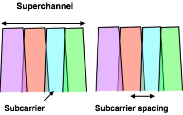
2.4 Multi-band OFDM spectrum . . . 29
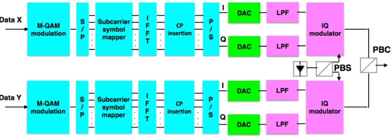
2.5 Transmitter set-up for the generation and processing of one OFDM band . . . . 30
2.6 MB-DP-CO-OFDM receiver set-up . . . 31
2.7 DP-OFDM demodulation and signal detection . . . 31
2.8 Nyquist WDM superchannel system . . . 34
2.9 Nyquist WDM transmitter set-up . . . 34
2.10 Nyquist WDM receiver set-up . . . 35
2.11 DBP principle for dual-polarization system . . . 37
2.12 VNLE principle for dual-polarization system . . . 40
2.13 Realization of nonlinear equalization for stage k . . . 41
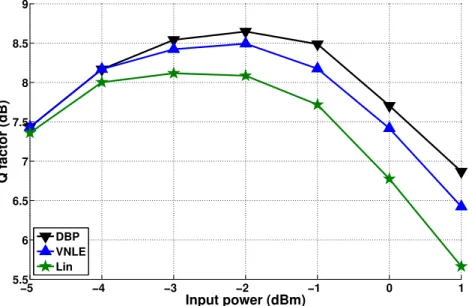
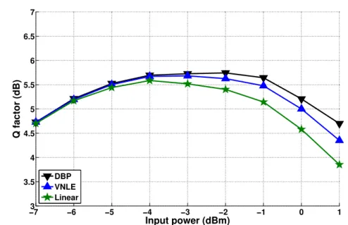
2.14 Input power vs. Q factor for single-band dual-polarization OFDM transmission . 42 2.15 Input power vs. Q factor for four-band dual-polarization OFDM transmission . . 42
2.16 Input power vs. Q factor for four-band dual-polarization Quasi-Nyquist WDM
transmission . . . 43
2.17 Input power vs. Q factor for four-band dual-polarization Super-Nyquist WDM transmission . . . 44
3.1 System Q formed by tandem connection of K(p)and H . . . 46
3.2 Realization of fifth-order VNLE for single polarization system . . . 55
3.3 Fifth-order IVSTF scheme for single-polarization . . . 58
3.4 Scheme for Q(k,`)1,x (ω) . . . 62
3.5 Scheme for Q(k,`)2,x (ω) . . . 63
3.6 Scheme for Q(k,`)3,x (ω) . . . 64
3.7 Q facor vs. input power for single-band single-pol 16-QAM OFDM (2000km) . . 65
3.8 Input power vs. transmission reach for 4-band single-pol 16-QAM OFDM . . . . 66
3.9 Q factor vs. input power for 4-band single-pol 16-QAM OFDM (2000km) . . . . 66
3.10 Q factor vs. input power for single-band dual-pol 16-QAM OFDM (2000km) . . 67
4.1 DFE block diagram . . . 70
4.2 INIC receiver structure . . . 71
4.3 Constellations: (A) linear equalization; (B) VNLE; (C) Proposed INIC(3,3) . . . 74
4.4 BER vs. input power for 4-band Single-Pol-16QAM OFDM . . . 75
4.5 BER vs. input power for 4-band Dual-Pol-16QAM OFDM . . . 75
4.6 Qfactor vs. input power (ρ = 0.1, δ = 1) . . . 76
4.7 Qfactor vs. subcarrier spacing factorδ (ρ = 0.1) . . . 77
4.8 Transmission reach vs. input power (ρ = 0.1) . . . 78
4.9 Qfactor vs. input power (ρ = 0.01, δ = 0.95) . . . 78
4.10 Q factor vs. subcarrier spacing factorδ (ρ = 0.01) . . . 79
B.1 système de transmission WDM . . . 99
B.2 Récepteur à diversité de phase et de polarisation . . . 101
B.3 Spectre de l’OFDM multi-bande . . . 101
B.4 Spectre de Nyquist WDM . . . 101
B.5 Architecture de l’émetteur OFDM multi-bande . . . 102
B.6 Architecture de récepteur OFDM multi-bande . . . 103
B.7 OFDM démodulation . . . 103
B.8 Architecture de l’émetteur Nyquist WDM . . . 104
B.9 Architecture du récepteur Nyquist WDM . . . 105
B.10 Facteur Q vs. la puissance injectée par bande pour une transmission OFDM double-polarisation et mono-bande . . . 106
B.11 Facteur Q vs. la puissance injectée par bande pour une transmission OFDM double-polarisation et multi-bande . . . 106
B.13 Schéma d’implémentation du terme Q(k,`)2,x (ω) . . . 110
B.14 Schéma d’implémentation du terme Q(k,`)3,x (ω) . . . 111
B.15 Implémentation du VNLE de cinquième ordre . . . 111
B.16 Facteur Q vs. Puissance injectée pour une transmission mono-polarisation et mono-bande 16QAM OFDM (2000km) . . . 112
B.17 Puissance injectée vs. distance de transmission pour une transmission mono-polarisation et 4-bandes 16QAM OFDM . . . 113
B.18 Facteur Q vs. Puissance injectée pour une transmission mono-polarisation et 4-bandes 16QAM OFDM (2000km) . . . 113
B.19 Facteur Q vs. Puissance injectée pour une transmission double-polarisations et mono-bande 16QAM OFDM (2000km) . . . 113
B.20 INIC receiver structure . . . 114
B.21 Facteur Q vs. Puissance injectée pour une transmission mono-polarisation et 4-bandes 16QAM OFDM . . . 117
B.22 Facteur Q vs. Puissance injectée pour une transmission double-polarisations et 4-bandes 16QAM OFDM . . . 117
B.23 Facteur Q vs. la puissance injectée (ρ = 0.1, δ = 1) . . . 118
B.24 Facteur Q vs. facteur d’espacement de sous-porteusesδ (ρ = 0.1) . . . 118
B.25 Distance de transmission vs. la puissance injectée (ρ = 0.1) . . . 118
B.26 facteur Q vs. la puissance injectée (ρ = 0.1, δ = 1) . . . 119
2.1 WDM system classes . . . 33
4.1 OFDM parameters . . . 74
4.2 Simulation parameters . . . 76
ADC Analog to Digital Convertor
ASE Amplified Spontaneous Noise
AWGN Additive White Gaussian Noise
BER Bit Error Rate
CD Chromatic Dispersion
CFO Carrier Frequency Offset
CMA Constant Modulus Algorithm
CO Coherent Optical
CP Cyclic Prefix
CPE Common Phase Error
DAC Digital to Analog Convertor
DBP Digital Back Propagation
DCF Dispersion Compensation Fiber
DD Decision Directed
DFE Decision Feedback Equalizer
DGD Differential Group Delay
DP Dual-Polarization
DSF Dispersion Shifted Fiber
DSP Digital Signal Processing
EDFA Erbuim-Doped Fiber Amplifier
ENOB Effective Number Of Bits
FEC Forward Error Correction
FFT Fast Fourier Transform
FIR Finite Impulse Response
FWM Four Wave Mixing
GN Gaussian Noise
GD Group Delay
GVD Group Velocity Dispersion
ICI Inter-Carrier Interference
IFFT Inverse Fast Fourier Transform
INIC Inter-band/subcarrier Nonlinear Interference Canceler
ISI Inter-Symbol Interference
IVSTF Inverse Volterra Series Transfer Function
LEAF Large Effective Area Fiber
LED Light-Emitting Diode
LO Local Oscillator
LPF Low Pass Filter
MB Multi-Band
MDM Mode Division Multiplexing
MIMO Multiple Input Multiple Output
MZM Mach-Zehnder Modulator
MZI Mach-Zehnder interferometer
NF Noise Figure
NLE NonLinear Equalizer
NLSE NonLinear Schrodinger Equation
NZDSF Non-Zero Dispersion Shifted Fiber
NRZ-OOK Non-Return-to-Zero On/Off Keying OEO Optical-to-Electrical-to-Optical
OFDM Orthogonal Frequency Division Multiplexing
OOK On/Off Keying
OSNR Optical Signal to Noise Ratio
PBC Polarization Beam Combiner
PBS Polarization Beam Splitter
PDL Polarization Dependent Loss
PDM Polarization Division Multiplexing
PMD Polarization Mode Dispersion
QAM Quadrature Amplitude Modulation
QPSK Quaternary Phase Shift Keying
RDE Radius Directed Equalizer
ROADM Reconfigurable Optical Add Drop Multiplexer
RRC Root Raised-Cosine
SDM Spacial Division Multiplexing
SNR Signal to Noise Ratio
SOP State of Polarization
SPM Self-Phase Modulation
SMF Single Mode Fiber
SSMF Standard Single Mode Fiber
TDM Time Division Multiplexing
VSTF Volterra Series Transfer Function
WDM Wavelength Division Multiplexing
WSS Wavelength Selective Switch
XPM Cross-Phase Modulation
XPolM Cross-Polarization Modulation
Problem statement
Optical fiber communication systems have played an important role in the evolution and devel-opment of modern communications networks. Due to their low cost, low attenuation and high bandwidth, optical fibers have dominated the area of long-haul terrestrial and transoceanic transmission. In addition to access and metro networks, today Fiber-to-the-Home (FTTH) sys-tems are also available. Since their deployment in the 1970’s, optical communication syssys-tems have evolved to meet the continuous grow of global demand for communication capacity. The invention of EDFA and the deployment of WDM technology have been the first breakthrough that stimulate the use of optical communication systems. Different fiber technologies had used to deal with transmission impairments such as dispersion and attenuation. Then, fiber capac-ity evolution had slowed down because of the full exploitation of the amplifier bandwidth, before it was revived by the re-introduction of coherent detection based systems in the early 2000’s. Coherent based technology allowed the increase of spectral efficiency by exploiting new degrees of freedom. Polarization and phase, in addition to amplitude used in direct de-tection based systems, are available in coherent systems and can be used to increase spectral efficiency and so that fiber capacity. As a result, optical transmission has migrated from the use of OOK to multi-level modulation formats. An other important point that characterizes coher-ent detection based systems is the possibility of combination with DSP techniques to combat fiber distortion.
Fiber capacity increase is still required to face the ever increase of traffic demands driven by the growth of mobile, video and cloud services and machine-to-machine communications. According to Cisco Visual Networking Index[1], metro and long-haul traffic will triple between 2014 and 2019. The next generation of long-haul WDM transmission systems are expected to operate at 400Gbps/1Tbps per WDM wavelength whereas the most recent commercial fiber operates at 100Gbps. Such high bit rate is difficult to achieve without finding new technologi-cal paths. Actually, the classic ways to increase data rate, by increasing the symbol rate and/or encoding more bits per symbol, face several challenges that make their practical implementa-tions impossible. Increasing the symbol rate to generate 400Gbps/1Tbps requires a very high speed optical and electronic components which are not commercially available today and in
the near future. On the other hand, very high spectral efficiency modulation are needed to generate these high bit rates. Such modulation formats require very high optical signal to noise ratio (OSNR) which strongly increases the sensitivity to fiber nonlinear effects. Due to nonlin-ear effects, sending 400Gbps/1Tbps over a WDM wavelength can reach only few hundreds of kilometers if only linear processing is carried out at the receiver side which is not the desired transmission reach in the context of long-haul transmission. Therefore, nonlinear processing at the receiver side is crucial for the next generation of long-haul WDM transmission systems. In addition, new way for using a WDM wavelength has been proposed, called superchannel approach, which consists in split a WDM wavelength into several optical bands with small guard-band between them. This approach enables an easier practical implementation by sam-pling with respect to the band instead of the wavelength. Two kinds of superchannel based on Nyquist WDM and multi-band OFDM are now subject of research investigations to evaluate their performance. Superchannel systems combined with multi-level modulation formats can be considered as promising candidates in terms of practical implementation and performance. However, superchannel transmission is also vulnerable to fiber nonlinear effects. Kerr-induced nonlinear effects such as self-phase modulation (SPM), phase modulation (XPM), cross-polarization modulation (XpolM) and four-wave mixing (FWM) depending on bite rate and interval guard, reduce the transmission performance and their mitigation is required.
Contributions of the thesis
Our work has been funded by the SASER-SIEGFRIED European program. Our contribution consists in developing new DSP algorithms for the next generation of long-haul WDM trans-mission systems. In the context of superchannel transtrans-mission systems, fiber nonlinear effects are considered as the major constraint and their mitigation is a hot topic to get the desired performance in terms of transmission reach. Many works on Digital Back Propagation and third-order Volterra series have been proposed. Nevertheless, gain in performance is still nec-essary. Therefore, we developed new techniques to compensate for nonlinear effects in optical fiber.
To deal with intra-band nonlinear effects in multi-band OFDM superchannel, we developed a fifth-order Volterra based nonlinear equalizer (VNLE). The main idea of this technique is increasing the order of Volterra based nonlinear equalizer. We first derived mathematically the fifth-order Volterra kernels which characterize the nonlinear equalizer. Then, we proposed a practical implementation scheme. The performance of the proposed technique are evaluated by simulation and a significant gain is observed in comparison with third-order VNLE in certain configurations.
We observed a reduction of performance of our proposed fifth-order VNLE and the classic approaches such as digital back-propagation (DBP) and third-order VNLE in case of multi-band transmission. As a result, we proposed a nonlinear interference canceler to compensate for nonlinear interference in the context of superchannels based on band OFDM and
multi-subcarrier Nyquist WDM. The proposed inter-band/subcarrier nonlinear interference canceler (INIC) significantly improve the performance in comparison with the classic nonlinear effects mitigation techniques.
Thesis outline
The thesis is organized as follows: in chapter 1, we briefly review the evolution of optical fiber communication systems. We highlight the technological breakthrough that characterized the evolution of fiber capacity like the deployment of WDM systems and the revival of coherent detection. Then, we focus on optical fiber impairments. We describe linear distortions and then we detail nonlinear effects because of their important impact in superchannel systems.
In chapter 2, we briefly give the principle of high spectral efficiency modulation formats. The second part of this chapter is dedicated to the system models. We describe superchannel transmission systems for both multi-band OFDM and Nyquist WDM approaches. After that, we give the state of the art about nonlinear effects compensation techniques.
In chapter 3, we propose the fifth-order Volterra based nonlinear equalizer. A derivation of fifth-order Volterra operators and a practical implementation scheme are given for single-polarization and dual-single-polarization configurations. Then, simulations are done to evaluate the performance of the proposed technique in the context of OFDM based superchannel.
In chapter 4, we propose an inter-band nonlinear interference canceler. This approach combats nonlinear interference in multi-band OFDM and Nyquist WDM superchannels. Sim-ulation results are given before introducing a complexity analysis of the proposed nonlinear interference canceler.
Publications
Journal Papers
J1 A. Amari, P. Ciblat, and Y. Jaouen, “Inter-subcarrier Nonlinear Interference Canceler for
Long-Haul Nyquist-WDM Transmission,” IEEE Photonics Technology Letters (PTL). vol. 28, no. 23, pp. 2760-2763, December 2016.
International Conferences
C1 A. Amari, P. Ciblat, and Y. Jaouen,“Fifth-order Volterra series based Nonlinear
Equal-izer for long-haul high data rate optical fiber communications," Asilomar Conference on
Signals, Systems, and Computer, November 2014.
C2 V. Vgenopoulou,A. Amari, M. Song, E. Pincemin, I. Roudas, and Y. Jaouen,“Volterra-based Nonlinear Compensation in 400 Gb/s WDM Multiband Coherent Optical OFDM Systems," Asia Communications and Photonics Conference (ACP), November 2014.
C3 A. Amari, P. Ciblat, and Y. Jaouen,“Inter-Band Nonlinear Interference Canceler for
Long-Haul Coherent Optical OFDM Transmission,"IEEE/OSA Tyrrhenian International
S
TATE OF THE ART ABOUT OPTICAL
FIBER COMMUNICATION SYSTEM
In this chapter, we briefly describe the evolution of optical fiber communication systems. We emphasize the technological breakthroughs that stimulate the increase of fiber capacity such as the invention of EDFA and the deployment of coherent detection based systems. On the other hand we focus on fiber propagation impairments. We highlight fiber nonlinear effects because of their strong impact for the next generation of long-haul WDM systems.
1.1
Evolution of optical fiber transmission systems
Optical fiber communication uses light pulses to transmit information from a point to another. Semiconductor devices such as light-emitting diodes (LEDs) and laser diodes are used to gen-erate light at the transmitter. The transmission medium consists of an optical fiber which is a dielectric cylindrical waveguide made from low-loss materials such as silica. Light pulses propagate inside the fiber due to the internal reflection between the core and the cladding[2]. Signal amplification is required to deal with fiber loss, especially for long-haul and transoceanic transmission. At the receiver side, photo-detectors ensure the conversion of the transmitted signal to the electrical domain. The advantages that stimulate the use of optical fiber for com-munication systems are its low attenuation and wide spectral bandwidth compared to other communication systems. Today, optical communication systems are widely used to meet the rapidly increasing demand for telecommunication capacity and internet services. Actually, op-tical communication is unchallenged for the high transmission capacity with low latency in long-haul and transoceanic transmission.
Optical fibers were first introduced in the early 1970’s. Semiconductor AlGaAs was used as laser and transmission is carried out in the range of 800−850nm wavelength. The transmission performance were limited by material dispersion. The maximum transmission bit-rate-distance reached is about 1G b− km.s−1 for multi-mode fibers[2]. In the early 1980’s, single mode
fibers (SMF) with 1310nm wavelength, defined by the ITU-T as the standard G.652, were used to deal with fiber dispersion. In fact, the zero-dispersion wavelength is about 1268nm [3], and the fiber dispersion was reduced by adding waveguide dispersion material to shift the zero-dispersion to 1310nm[4]. SMF presented higher performance in terms of bandwidth and transmission reach in comparison with multi-mode fiber. Thus, it became the fiber of choice for long-haul transmission systems by 1984[5]. The need of increasing transmission distance had pushed fiber transmission to 1550nm wavelength which presents the lowest fiber loss as shown in fig.1.1. The attenuation value at 1550nm is about 0.2d B.km−1, while the corresponding
Figure 1.1: Fiber attenuation and dispersion for single-mode fibers[5]
attenuation at 1310nm is about 0.35d B.km−1. Then, transmission reach can be increased by 75% using 1550nm. At this value of wavelength, the fiber chromatic dispersion is about 17ps.nm−1.km−1 as shown in fig.1.1. Therefore, dispersion shifted fibers (DSF) were used and optimized to combat fiber dispersion by shifting zero dispersion wavelength to 1550nm.
At the receiver, intensity modulation and direct detection (IM-DD) scheme was commonly employed in optical communication systems for long time and attracted more attention than coherent detection scheme. Actually, IM-DD based receiver sensitivity is independent of the carrier phase and the state of polarization (SOP) of the received signal which are randomly fluctuating in real systems. IM-DD allows only amplitude based modulation formats and the decision is related to the signal intensity. A photo-detector ensures the conversion of the optical signal to the electrical domain by creating a current proportional to the signal intensity. The expression of the generated current is given by:
where R is the responsivity of the photo-detector and E is the amplitude of the optical field. The principle of direct detection based receiver is shown in fig.1.2.
vv
Signal
Figure 1.2: Direct detection
1.1.1
EDFA invention: Wavelength division multiplexing transmission
The first breakthrough in optical communications was the invention of the Erbium-Doped Fiber Amplifiers (EDFA) in the late 1980’s. It avoids the expensive optical-to-electrical-to-optical (OEO) regeneration. It also allows the amplification of a multiplex of optical signals with dif-ferent wavelength inside the amplifier bandwidth. EDFA band includes 1550nm wavelength as shown in fig. 1.1. A dramatic increase in system capacity was achieved through the ag-gregation of several wavelengths propagating simultaneously inside the SMF. This technique enabled by optical amplifiers is called wavelength division multiplexing (WDM). WDM tech-nology was developed in the mid-1990’s and it increased lightwave systems capacity to roughly 1Tbps by fiber around 2000[6]. More precisely, this rate is obtained through 80 WDM wave-length, each of them with 10Gbps. It consists in transmitting independent signals using dif-ferent wavelengths propagating simultaneously in the fiber. Wavelength aggregation is done using multiplexer at the transmitter, a demultiplexer at the receiver side splits them apart as presented in fig. B.1.
SMF
MU
X
D
EMU
X
RX
RX
TX
TX
.
.
.
.
.
.
. . .
Figure 1.3: WDM transmission system
Fig.1.4 shows the evolution of system capacity for WDM system in comparison with single channel time-division multiplexing (TDM) system in research demonstrations. WDM trans-mission allowed a significant increase of data rate from gigabits per second to over than one terabit per second. It has strongly increased system capacity in comparison with TDM.
DSF fibers used for single-wavelength transmission at 1550nm are not convenient for WDM systems. In fact, interactions between WDM channels lead to the generation of new signals at
Figure 1.4: Evolution of capacity for WDM (square marker) and TDM (disk marker) systems [7]
new frequencies because of nonlinear effects named four-wave mixing (FWM). FWM, detailed in section 1.2.5-c, causes crosstalk between WDM channels and it is inversely proportional to the fiber dispersion. Then, non-zero dispersion shifted fibers (NZDSF) were developed for WDM transmission to combat FWM[8]. NZDSFs with larger effective area such as LEAF were widely used for long-haul WDM transmission.
1.1.2
From 2.5Gbps to 10Gbps (per wavelength) non-coherent detection based
systems
WDM systems were deployed firstly with 40 wavelengths each of them with 2.5Gbps over 800km of standard SMF. Non-Return-to-Zero On/Off Keying (NRZ-OOK) was used as modu-lation formats. Accumulated chromatic dispersion (CD) was the major limitation to increase further the bit rate. Increasing data rate to 10Gbps per wavelength was made possible by using dispersion compensation fiber (DCF) in addition to forward error correction codes (FEC). DCF is used in concatenation with SMF as shown in fig.1.5. In order to compensate chromatic dis-persion, DCF has an opposite sign of dispersion with respect to the already installed SMF[9]. FEC consists in adding redundancy to the transmitted signal in order to make possible detec-tion and correcdetec-tion of errors at the receiver. The use of Reed-Solomon (RS) FEC codes, which provide about 6 dB gain in optical to signal noise ratio (OSNR), and Enhanced-FEC (EFEC) with 8.5 dB gain in OSNR had significantly increased the transmission performance[10].
DCF
SMF
MU
X
D
EMU
X
x N
RX RX TX TX.
.
.
.
.
.
Figure 1.5: WDM system with dispersion compensation fiber (DCF)
1.1.3
40Gbps coherent detection based systems
The migration of direct detection based OOK systems from 10Gbps to 40Gbps per wavelength was challenged by different fiber impairments. In fact, polarization mode dispersion (PMD), which has negligible effect in 10Gbps, reduces drastically the transmission performance at 40Gbps. Indeed in non-coherent based communication (with OOK) passing from 10Gbps to 40Gbps leads to divide the bit period by 4 which decreases also the tolerance on the PMD by 4. In addition, CD tolerance is divided by a factor of 16 at 40Gbps and that requires an increase of OSNR by 6d B to get similar performance to OOK 10Gbps systems[11]. This high increase of OSNR leads to a strong nonlinear distortion. An other way to increase the rate was to increase the number of WDM wavelength, but this is a very limited option due to the optical amplifier bandwidth. These limitations oriented the researches to focus the possibility to increase the spectral efficiency and so to the use of coherent detection instead of direct detection. This is the second main breakthrough on the optical-fiber communications community.
1.1.3-a Coherent detection
Coherent detection was first introduced by DeLange in 1970[12]. Its complexity of implemen-tation and the high performance of IM-DD systems meeting the desired fiber capacity made its deployment unnecessary. However, the need of increasing capacity and spectral efficiency and the availability of high speed ADCs/DACs has led to a revival of the coherent detection.
The introduction of coherent detection permitted the use of multilevel modulations formats due to the ability to detect the signal phase and amplitude. Thus, higher spectral efficiency can be achieved compared to direct detection technique. An other major advantage of co-herent detection is the possible combination with digital signal processing (DSP) algorithms. Therefore, fiber impairments can be mitigated efficiently in electrical domain and that avoids the use of DCF to combat CD. The principle of coherent detection is depicted in fig. 1.6. It consists in mixing the received signal with a continuous wave generated by a local oscillator (LO). LO produces a frequency very close to the frequency of the received signal and it serves as an absolute phase reference.
Phase diversity homodyne receiver and intradyne receiver are usually used to detect both in-phase and quadrature components of the optical signal simultaneously. This can be ensured
π/2 Signal LO II IQ Hybrid 90°
Figure 1.6: Coherent detection with Hybrid 90odevice
by using an 90◦ optical hybrid and the output photocurrents from the balanced photodiodes are then given by[13]:
II(t) = RpPsPlcos(θs(t) − θl(t)) (1.2)
IQ(t) = RpPsPlsin(θs(t) − θl(t)) (1.3)
where Ps, Pl,θsandθlare the powers and phases of the received signal and the local oscillator respectively. Therefore, the complex amplitude or the baseband signal can be expressed as:
Ic(t) =II(t) + jIQ(t) (1.4) =RpPsPle[j(θs(t)−θl(t))]. (1.5)
After that, DSP techniques are used to deal with fiber impairments such as dispersion and nonlinear effects.
Coherent-based technology has been used instead of direct detection-based technology in the 40Gbps and the current 100Gbps standard technology for optical long-haul WDM systems. Thanks to coherent detection, in addition to the phase and the amplitude, polarization of the received signal is also available and it can be used to increase the spectral efficiency. In fact, due to polarization division multiplexing (PDM), transmission bit rate can be doubled easily. Therefore, PDM, known also as dual-polarization transmission, is widely used in coherent optical transmission systems.
1.1.3-b Polarization division multiplexing
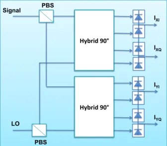
Polarization division multiplexing allows more efficient use of the available bandwidth. It en-ables a factor of two increase in spectral efficiency since the data rate is twice without increas-ing the symbol rate. In PDM systems, both orthogonal polarization at the same wavelength are used to transmit independent data. A coherent phase and polarization diversity receiver is used to detect both polarizations as shown in fig. B.2.
Signal LO Hybrid 90° Hybrid 90° x PBS PBS IXI IYQ IXQ IYI
Figure 1.7: Block diagram of phase and polarization diversity coherent receiver
PDM technique has been used in 40G bps long-haul WDM systems and beyond. However, dual-polarization transmission suffers from several impairments such as polarization mode dis-persion (PMD) and nonlinear cross-polarization modulation (XPolM) which reduce the trans-mission performance.
1.1.3-c Digital signal processing algorithms
The deployment of coherent detection with DSP algorithms has enabled offline compensation for fiber impairments. DSP based fiber impairments compensation can be easily and efficiently implemented at the receiver to equalize the received signal after the analog to digital conver-sion (ADC). It can be also performed at the transmitter side to predistort the transmitted signal before the digital to analog conversion. The different stages of DSP at the receiver are shown in fig. 1.8.
Figure 1.8: DSP blocks for coherent receiver
Several approaches have been proposed to combat CD and PMD. Research works are cur-rently oriented to other fiber impairments such as polarization dependent loss (PDL) and non-linear effects which their impacts become more and more important in high data rate systems.
Then, a frequency offset and carrier recovery are done before signal detection and decision. These DSP algorithms will be detailed in section 2.2.
1.1.4
100 Gbps coherent systems
After the commercialization of 40Gbps coherent technology in the mid of 2000s, 100Gbps (per wavelength) coherent system was chosen to be the next standard technology for optical transport network (OTN) to meet the growth of traffic demands [14]. Several approaches are proposed for 100Gbps coherent systems such as dual-polarization Quaternary phase-shift keying (DP-QPSK) systems and orthogonal frequency-division multiplexing (OFDM) based systems[15].
In fact, by placing 88 WDM channels at 50GHz-spaced grids, a total capacity of 8.8T bps through a single fiber and a spectral efficiency of 2 can be achieved[7][13]. 8.8T bps is com-mercialized today by Alcatel-Lucent for 100Gbps DP-QPSK per waverlength over a distance of 4000km. A 17.6T bps (88x200Gbps DP-16-QAM) is also available for a transmission distance of 1000km. PacketLight Networks has proposed 100Gbps (DP-QPSK) coherent systems which can reach up to 2000km for ultra-long-haul networks. 100Gbps coherent systems for OTN are also commercialized by ZTE Corporation, Ciena, Huawei and Infinera...
1.1.5
Fiber capacity limit
The introduction of coherent detection and dual-polarization in WDM transmission systems have increased the spectral efficiency. Fig. 1.9 shows the spectral efficiency achieved in re-search demonstrations versus year[7].
Figure 1.10: Nonlinear fiber (Gaussian) capacity limits for a range of transmission distance [7]
Spectral efficiency improvement has revived the increase of fiber capacity after it had slowed down because of the full exploitation of the amplifier bandwidth. The strong traffic demand increase requires a continuous improvement of system capacity. The next generation of long-haul WDM systems is expected to operate at 400Gbps or 1Tbps per wavelength. Such high bit rate is extremely difficult to achieve without finding new technological paths. The use of multi-level modulation formats faces a serious challenge which is fiber nonlinear ef-fects. Advanced modulation formats require higher optical signal-to-noise ratio (OSNR) and so that higher input powers. Such input powers lead to the increase of sensitivity to fiber nonlinear effects, that significantly reduces the transmission reach. In fact, the optical fiber is a nonlinear transmission medium due to Kerr effect[16]. Fiber capacity is limited by noise at low power and by fiber nonlinearity (if the transmit waveform is not modified and adapted to nonlinearity) at high input power as shown in fig. 1.10.
Space-division multiplexing (SDM) (such as multi-core fibers (MCF) or mode-division mul-tiplexing (MDM)) are proposed to meet the ever growth in traffic demands. The first one consists in inserting several independent cores per fiber and the total fiber capacity can thus be increased according to the number of cores [7]. MDM can be used in multi-mode fibers [17]. An increase of capacity can be realized according to the number of supported orthog-onal modes. Transmission impairments can be mitigated using digital signal processing to increase system performance . SDM techniques are investigated in research demonstrations but they still do not meet the desired performance in terms of transmission reach in long-haul
transmission.
Thus, SMF is still the chosen fiber in long-haul transmission systems. To meet the increased demands in SMF capacity, researches are focused to find new approaches to increase system capacity and to achieve the expected high bit rate for the next generation of long-haul WDM systems. An aggregation of optical subcarriers with small guard-band is proposed[18]. This technique, called superchannel transmission, is a potential candidate for the next generation in combination with multi-level modulation formats. Researches now are concentrated in evaluating the performance of two types of superchannels based on OFDM and Nyquist-WDM systems.
1.2
Optical fiber transmission impairments
Long-haul transmission over SMF suffers from several limitations[2]. Fiber loss causes the attenuation of the propagating optical power and so that signal amplification is required peri-odically. Amplifier such as EDFA generates amplified spontaneous noise (ASE) and the accu-mulation of ASE noise reduces transmission performance. In addition, fiber dispersion such as chromatic dispersion (CD) and polarization mode dispersion (PMD) cause intersymbol in-terference (ISI). At high date rate transmission, nonlinear effects become more important and their compensation is necessary to maintain long transmission distance. These differ-ent kinds of optical fiber impairmdiffer-ents are presdiffer-ented by the simplified version of the nonlinear Schrodinger equation (NLSE) that governs the wave propagation inside an SMF:
∂ E ∂ z + j β2 2 ∂2E ∂ t2 + α 2E= jγ|E| 2E (1.6)
where E is the electric field envelope of the optical signal,α is the fiber attenuation coefficient,
β2is the second-order dispersion parameter andγ is the nonlinear coefficient of the fiber.
In followings subsections, we highlight the causes and the impacts of optical fiber impair-ments.
1.2.1
Attenuation
The optical power propagating along the fiber decreases exponentially with the transmission distance. The expression of attenuation is given by:
α [dB.km−1] = 10 L log10 P 0 P (1.7)
where L is the fiber length or the span length in multi-span fiber. P0 and P are the input and output optical power respectively. Fiber loss is induced by different mechanisms mainly: material absorption, Rayleigh scattering and bending losses.
Material absorption is the conversion of the electromagnetic wave energy into other forms such as vibration. It can be intrinsic caused by the fiber material silica and it occurs in infrared and ultraviolet bands. An other type of absorption is related to impurities in the fiber. The
most important impurities causing extrinsic absorption in the fiber is OH−ions. The significant
OH−losses occur at 950nm, 1250nm and 1380nm. SMF standard G.652 has not an OH−peak at 1380nm and that allows the transmission in the entire region located between 1300nm and 1700nm.
Rayleigh scattering is due the material inhomogeneities with a size smaller than length. It depends on wavelength and the related loss is inversely proportional to the wave-length αR ∼ λ14. Thus, Rayleigh scattering loss is reduced at high wavelength. However, it restricts the use of fibers at short wavelength.
Macroscopic and microscopic bends cause also fiber loss. Macrobending losses appear when installing fibers and are negligible in practice. Microbending losses are due to the local distortions of fiber geometry.
Figure 1.11: Attenuation of optical fiber[19]
Fig. 1.11 shows the different mechanisms responsible for fiber loss[19]. In standard SMF, the fiber loss is about 0.2d B.km−1around the transmission wavelength 1550nm. In long-haul transmission system, multi-span fiber separated by amplifiers is used to deal with fiber loss. The typical distance between amplifiers is between 80 and 100km for a total transmission distance of 1500− 3000km.
1.2.2
Chromatic dispersion
In SMF, the energy of the injected pulse is transported by a single mode which is the funda-mental mode. Thus, the advantage of SMF is the absence of intermodal dispersion but it is still affected by intramodal dispersion or chromatic dispersion. CD includes two types of
dis-persion: material dispersion and waveguide dispersion. the first one is due to the dependence of the refractive index of silica, the material used for fiber fabrication. The waveguide disper-sion is caused by the structure and the geometric properties of the optical fibers. In eq.1.6,
β2is the term responsible for CD in optical fiber. It is also known as the GVD parameter. The
wavelengthλDcorresponding toβ2= 0 is called zero dispersion wavelength. The value of the CD is characterized by the coefficient of chromatic dispersion D. The coefficient D is related toβ2by the following expression:
D= −2πc
λ2 β2 (1.8)
It depends on wavelengthλ. When D < 0, the fiber has normal dispersion and the lowest wavelength components of the optical pulse travel slower than the highest wavelength com-ponents. In the case of D> 0 (which is our case), the fiber is called with anomalous dispersion.
Figure 1.12: Inter-symbol interference due to chromatic dispersion
CD causes pulse broadening which leads to inter-symbol interference (ISI) as shown in fig.1.12. ISI reduce significantly the transmission performance and CD compensation is re-quired. Several techniques are proposed to compensate CD such as the use of dispersion compensating fibers (DCFs) in concatenation with SMF[20]. However, this kind of approach increases the fiber sensitivity to nonlinear effects because of their reduced effective core area. In SMF standard G.652 fiber used in our work, the value of the CD coefficient D is approx-imatively 17ps.nm−1.km−1at 1550nm wavelength.
1.2.3
Polarization mode dispersion
The fundamental mode of an SMF consists of two orthogonal components known as polariza-tion states. Thus, in case of dual-polarizapolariza-tion transmission, the injected optical pulse attacks the two polarization components and propagates inside the SMF in the two directions x and y. Unfortunately, because of manufacturing process, the optical fiber is not ideal circular and ho-mogeneous, the core has not perfect symmetry and that leads to modal birefringence. In fact, because of core asymmetry, the refraction indexes of polarization x and y are different and the two polarizations travel inside the fiber with different velocities. The strength of modal birefringence can be expressed as[2]:
where nx and ny are the modal refractive indexes for the two polarization states x and y respectively.
Figure 1.13: Illustration of polarization mode dispersion
As presented in fig. 1.13, birefringence causes a delay between the two orthogonal states of polarization during the propagation. This delay ∆τ is known as differential group delay (DGD). DGD is not deterministic and it varies wildly with the wavelength and the time due to deployment conditions such as thermal and mechanical stresses. The average of DGD is referred to as PMD. The optical fiber can be modeled as a concatenation of birefringence segments with random axis variation. The concatenation of equal sections of birefringent fiber can be presented by the Jones matrix (given in hte frequency domain) as[21] :
T(ω) = N Y n=1 Bn(ω)R(αn) (1.10) = N Y n=1 ep3π/8bωphn/2+φn 0 0 e−p3π/8bωphn/2+φn ! cosαn sinαn − sin αn cosαn (1.11)
where N is the number of segment, Bnrepresents the birefringence matrix of n-th segment with
hn length, R is the matrix of a rotator that the random coupling angles between the segment
axes, b is the PMD coefficient of the fiber andω is the optical frequency. The phase φnaccounts for the small temperature variation along the fiber. The DGD∆τ can be calculated based on the eigenvalues of the matrix(∂ωT(ω))T−1(ω).
PMD is a potential source of pulse broadening which leads to strong ISI and it increases linearly with the data rate. In coherent transmission systems, MIMO processing techniques are used to mitigate PMD[22].
1.2.4
Optical amplification
In long-haul optical transmission, signal attenuation can be reduced by introducing optical amplifiers. Optical amplification presents two main advantages. It allows the use of WDM transmission system and it avoids optical to electrical to optical conversion which requires high-speed electronics. Rare earth doped fiber such as EDFA are mainly used as fiber amplifier for optical transmission systems. Currently, Raman amplification is also investigated to eval-uate its performance. EDFA amplification process and its effect in optical fiber transmission systems are detailed in the following.
1.2.4-a EDFA
EDFA consists of Erbium doped Silica SMF pumped by semiconductor lasers at 980nm and 1480nm[23]. EDFA uses stimulated emission to amplify the transmitted optical signals and the principle is based on exciting Erbium ions E r3+ to higher energy level. At 980nm, Erbium ions from ground level L1 are excited into energy state L3[24]. The life time of Er3+in L3is about 1µs. After that, Erbium ions fall into metastable level L2. Pump can also work at 1480nm to excite E r3+ions directly to energy state L2. This phenomena is called population inversion
because the number of atoms at high energy level are higher than those of low energy level [25]. The optical signal passing through EDFA excites Er3+ ions to return to energy level L
1.
This return is accompanied with photons emission at the range of 1520nm to 1570nm wave-length. This process is known as stimulated emission. Generated photons due to stimulated emission have the same properties as the signal and are responsible for signal amplification. Unfortunately, stimulated emission is accompanied by spontaneous emission. In fact, as the electrons have a finite excited state life time, some of the electrons return spontaneously to the ground state L1 and emit photons with random phase. Some of these photons propagate in
the direction of the signal as noisy photons and they are also amplified. This process is called amplified spontaneous emission (ASE). Fig. 1.14 details the principle of EDFA process with stimulated and spontaneous emission.
1.2.4-b Inline optical amplification
In long-haul transmission system, the transmission link consists of N spans equally spaced and separated by EDFAs. The use of EDFAs results in the generation of ASE noise. ASE noise reduces significantly the transmission performance. It is commonly considered as additive white Gaussian noise (AWGN). The power spectral density of ASE for a given polarization is expressed as:
NAS E= (G − 1)hνnsp (1.12) where G is the EDFA gain, h= 6, 63×10−34m2.k g.s−1is Plank’s constant andν is the frequency of light. hν corresponds to the photon energy and nsp is the spontaneous emission factor (typically between 1 and 1.5).
Spontaneous
emission
1520-1570 nm
Signal
1550 nm
Pump
1480 nm
Pump
980 nm
L3
L2
L1
τ = 1µs
Stimulated
emission
1550 nm
Figure 1.14: Principle of EDFA process
In case of N -span fiber transmission as shown in fig.1.15, the optical signal to noise ratio
Figure 1.15: Multi-span SMF with EDFA amplifiers
(OSNR), for a reference optical bandwidth Br e f, is given by:
OSN R= P
2N NAS EBr e f (1.13)
where P is the total average signal power summed over the two states of polarization. The factor 2 corresponds to ASE power on two polarizations and Br e f is usually chosen Br e f = 12.5GHz which correponds to a gap in wavelength equal to 0.1nm.
1.2.5
Nonlinear effects
The increase of fiber capacity and spectral efficiency in long-haul transmission systems give rise to nonlinear effects in the optical link. In fact, due to Kerr effect, the refractive index of the optical fiber depends on the intensity of the transmitted signal as[16]:
n(P) = n0+ n2I(t) = n0+ n2
P(t)
where n0 and n2 are the linear and nonlinear refractive index respectively, I is the signal intensity, P is the signal power and Ae f f is the effective core area. The increase of the optical power or the decrease of the effective core area leads to the increase of nonlinear effects in the fiber.
In eq.1.6, nonlinear effects are presented by the nonlinear coefficientγ given by:
γ = 2πn2
λAe f f
(1.15)
Kerr effect induces different kinds of nonlinear effects depending in the optical signal power and the channel spacing in case of multi-channel transmission such as Self-phase modu-lation (SPM), Cross-phase modumodu-lation (XPM), Four wave mixing (FWM) and Cross-polarization modulation (XPolM).
Nonlinear effects can be also caused by inelastic scattering like Stimulated Brillouin Scat-tering (SBS) and Stimulated Raman ScatScat-tering (SRS). Raman and Brillouin scatScat-tering are inelastic processes in which part of the optical wave power is absorbed by the optical medium. These effects can be neglected because they manifest only at input powers higher than the typical value used in optical transmission system.
Kerr-induced nonlinear effects are detailed in the following subsections. Notice that other classifications such as those given in [26] exist especially for multi-band systems where the non-linear interference comes from three different origins : the self channel interference (SCI) where the signal of the band of interest creates its own interference, the cross-channel inter-ference (XCI) where the interinter-ference corresponds to a term where the signal of the band of interest and the other bands are, and the multi-channel interference (MCI) where a terme depending only on the other bands disturbs the band of interest.
1.2.5-a Self-phase modulation (SPM)
SPM consists in signal phase change due to interactions between the propagating signal and the optical fiber. In fact, the variation of signal intensity during the propagation inside the fiber induces the variations of the refractive index, and that leads to the modification of signal phase. Thus, the nonlinear phase variation is self-induced and the related phenomena is called SPM. SPM causes spectral broadening of the optical pulse. It increases in transmssion system with high input power because the chirping effect is proportional to the transmitted power.
The optical field propagating over an SMF with length L introduces a nonlinear phaseφN L expressed as:
φN L(t) =
2π
λ n2I(t)L = γLe f fP(t) (1.16)
where Le f f is the effective length given by:
Le f f =
1− e−αL
SPM-induced spectral broadening degrade the performance of long-haul optical transmis-sion system. Next generation of long-haul WDM system requires the use of high spectral effi-ciency modulation formats which necessitate the injection of high input power. The effect of SPM becomes more important with high transmitted power. Several DSP techniques have been proposed to deal with SPM and nonlinear effects in general such as digital back propagation and Volterra based-nonlinear equalizer and that will be detailed later in section 2.3.
1.2.5-b Cross-phase modulation (XPM)
Transmission systems are currently not limited to single-channel systems. Multi-channel trans-mission used in WDM systems and subcarrier multiplexing used in superchannel approaches for the next generation system generate an other type of nonlinear phase modulation called XPM. In fact, the fiber refractive index depends not only on the intensity of its related opti-cal signal but also on the intensity of other copropagating signals. XPM occurs when two or more optical signals with different wavelength copropagate inside the fiber. As a result, the nonlinear phase shift of a channel with wavelengthλj depends on its power Pj and also on the power of other copropagating channel due to XPM. The expression of the nonlinear phase shift is given by:
φj N L(t) = γLe f f Pj(t) + 2 N X m6= j Pm(t) (1.18)
The first term of the above equation corresponds to the SPM contribution in the nonlinear phase shift while the second term refers to the nonlinear phase shift induced by XPM and related to adjacent propagating channels. The factor 2 indicates that XPM is twice more effec-tive than SPM for the same amount of power[16]. XPM is effective only when the interacting signals are overlapped.
As SPM, XPM reduces the transmission performance by chirping frequency and chromatic dispersion. It does not engender energy transfer between copropagating optical fields. In the presence of CD, XPM can be reduced by increasing the wavelength spacing. In this case, the propagation constants of these channels become sufficiently different. So, copropagating pulses walk away from each other. This walk-off phenomenon limits the interaction time between channels and the XPM effect is reduced.
XPM effect is inversely proportional to the channel spacing and it increases with the num-ber of channels or subcarriers in the context of superchannel transmission. Superchannel approaches are expected to be used for the next generation of long-haul WDM transmission system due their high spectral efficiency. They consist on subcarrier multiplexing with small guard-band. In this context, XPM is more important and its compensation is a hot topic to maintain high system performance.
1.2.5-c Four-wave mixing (FWM)
Unlike SPM and XPM which result in nonlinear phase shift in the optical field, FWM process leads to energy transfer between copropagating channels. Physically, the origin of FWM pro-cess lies on nonlinear response of material bound electrons to the applied optical field. In fact, the magnitude of the polarization induced in the medium, which contains linear and nonlin-ear terms, is governed by the nonlinnonlin-ear susceptibilities. Second order nonlinnonlin-ear susceptibility vanishes due to the isotropic property of silica used for SMF, while the third order nonlinear susceptibilityχ(3) is responsible for generation of FWM process[16]. The induced nonlinear polarization is related toχ(3) in case of monochromatic plane waves such as WDM signal as :
PN L= ε0χ(3).E3 (1.19)
The derivation of eq.1.19 shows that for carrier frequenciesωp, ωq andωr, FWM generates new signals at frequencyωpqr by combining these frequencies and it is given by[27]:
ωpqr= ωp+ ωq− ωr (1.20)
In multi-channel system with N wavelengths, the number of FWM-generated signals M is expressed as :
M= N
2(N − 1)
2 (1.21)
FWM process results in power transfer between copropagating channels. That leads to power depletion which degrades the performance of channels. In addition, FWM can be an inter-channel crosstalk if the generated signal fall into other copropagating channels. That re-sults in significant system performance degradation due to crosstalk among the channels. FWM depends on fiber dispersion and channel spacing. Fiber dispersion varies with wavelength, that means FWM-generated signal has different velocity than the original signals. Thus, increasing the fiber dispersion limits interactions between signals and reduces the power transfer to the new generated signals. Increasing the channel spacing decreases also FWM effect.
SPM and XPM are mainly related to the signal power and become more significant at high bit rate system. However, FWM effect is independent of the bit rate and is critically related to fiber dispersion and channel spacing. Therefore, FWM will be a serious limitation in the next generation long-haul WDM system due to the use of superchannel transmission with small guard-band.
1.2.5-d Cross-polarization modulation (XPolM)
Polarization division multiplexing is adopted today in optical transmission system due to its im-provement in spectral efficiency. It consists in transmitting the signal in both orthogonal State of Polarization (SOP) of the wavelength. In multi-wavelength transmission system, XPolM occurs when the SOP of a transmitted channel depends on the SOP of other copropagating

![Figure 2.3: Time domain OFDM signal for one OFDM symbol [34]](https://thumb-eu.123doks.com/thumbv2/123doknet/2909973.75588/47.850.226.624.472.762/figure-time-domain-ofdm-signal-ofdm-symbol.webp)