HAL Id: tel-01494829
https://pastel.archives-ouvertes.fr/tel-01494829
Submitted on 24 Mar 2017HAL is a multi-disciplinary open access archive for the deposit and dissemination of sci-entific research documents, whether they are pub-lished or not. The documents may come from teaching and research institutions in France or abroad, or from public or private research centers.
L’archive ouverte pluridisciplinaire HAL, est destinée au dépôt et à la diffusion de documents scientifiques de niveau recherche, publiés ou non, émanant des établissements d’enseignement et de recherche français ou étrangers, des laboratoires publics ou privés.
Formation and Characterization of Reduced Metal
Complexes in the Gas Phase
Madanakrishna Katari
To cite this version:
Madanakrishna Katari. Formation and Characterization of Reduced Metal Complexes in the Gas Phase. Chemical Physics [physics.chem-ph]. Université Paris Saclay (COmUE), 2016. English. �NNT : 2016SACLX091�. �tel-01494829�
NNT : 2016SACLX091
T
HÈSE DE DOCTORAT
DE
L’UNIVERSITÉ PARIS-SACLAY
PRÉPARÉE À
“
ÉCOLE POLYTECHNIQUE ”
E
COLED
OCTORALE N° 571 2MIB
Sciences Chimiques : Molécules, Matériaux, Instrumentation et Biosystèmes
Spécialité de doctorat Chimie
Par
Madanakrishna KATARI
Formation and Characterization of Reduced Metal Complexes in
the Gas Phase
Thèse présentée et soutenue à l'Ecole Polytechnique , le 24 Novembre 2016 : Composition du Jury :
Dr. Gilles Grégoire DR CNRS, Orsay Président
Dr. Dorothée Berthomieu DR CNRS, Montpellier Rapporteur
Prof. Carlos Afonso Université de Rouen Rapporteur
Dr. Ilaria Ciofini DR CNRS, Paris Examinateur
This thesis is dedicated to my parents
for their love, and endless support
Acknowledgement
It is a great pleasure for me to thank all the people who supported and helped me during the whole period of my doctoral programme. My first and deepest appreciation goes to my supervisor, Dr. Gilles FRISON, for his continuous guidance and support in all stages of my thesis. I would like to thank all his contributions of time, ideas and funding that made my Ph.D. His enthusiasm, passion and vast knowledge have inspired me to overcome all the abstacles and challenges all along my Ph.D. pursuit.
I am sincerely grateful to the jury members of my thesis including reviewers: Dr. Dorothée Berthonieu and Dr Carlos Afonso who spent their valuable time for serving on committee and giving me many invaluable comments and constructive advices to the thesis. I also thank to examiners of my thesis commitee Dr. Gilles Grégoire and Dr. Ilaria Ciofini.
I am thankful to the past director of laboratory Dr. Gilles Ohanessian for his acceptance for me to work as PhD studend and also present director Dr. Corinne Gosmini for her support along my thesis period.
I would like to thank Dr. Duncan Carmichael, Dr. Guillaume van der Rest and Edith Nicol, Vincent Steinmetz, Dr. Eleonore Payen de la Garanderie for their help during my experiments. I am really grateful to them for their constant and enthusiastic help in these three years.
I also acknowledge all my past and present colleagues and friends at Ecole Polytechnique. I thank them all name by name for providing the cheerful working environment.
Finally, I wish to thank my parents whose unconditional love provided me inspiration and was my driving force, and my wife for her endless love and continuous support through all the thesis time. I would not have made this far without them. I also express my gratitude to all my other family members and friends in India.
i
Table of Content
Chapter I: General Introduction
1Introduction Générale (in French) 3
(in English) 9
I.1. Reference 13
Chapter II: Methodology
15PartA: Experimental Methodology 17
IIA.1. Introduction 17
IIA.2. Tandem Mass Spectrometry 19
IIA.2.1. General view 19
IIA.2.2. FT-ICR mass spectrometry set-up 20
IIA.3. Fragmentation Techniques 24
IIA.3.1. Electron Capture Dissociation (ECD) 26
IIA.3.2. Electron TransferDissociation (ETD) 27
IIA.4. Infrared Multi-Photon Dissociation (IRMPD) 30
IIA.4.1. General view 30
IIA.4.2. Principles 30
` IIA.4.3 IR-Free Electron Laser (FEL) 33
IIA.5. Non-Innocent Ligands 37
IIA.5.1. General view 37
IIA.5.2. Structural evolution 38
IIA.5.3. Role of non-innocent ligands in organometallic complexes 41
Part B: Computational Methodology 45
IIB.1. General view 45
IIB.2. Density Functional Theory 47
IIB.2.1. Local Density Approximation (LDA) 51
ii
IIB.2.3. Meta-GGA functional 53
IIB.2.4. Hybrid functional 53
IIB.2.5. Long-range Corrected functional 54
IIB.3. Basis Sets 55
1B.3.1. Atom-Centered Basis Sets 56
1B.3.1.1. Minimal Basis Set 57
1B.3.1.2. Double-Zeta (DZ) and Triple-Zeta (TZ) Basis Set 57
1B.3.1.3. Split-Valence (SV) Basis Set 58
1B.3.1.4. Polarization (P) Basis Functions 58
1B.3.1.5. Diffuse Basis Functions 58
II. References 61
Chapter III: Formation of reduced metal complexes
69III.1. Introduction 71
III.2. Principles and organometallic complexes choice 73
III.3. ECD and ETD on dicationic complexes 76
III.3.1. Reduction of homoleptic dication complexes 76
III.3.1.1. ECD of [Zn(1)3]2+ 76
III.3.1.2. ETD of [Zn(1)3]2+ 78
III.3.1.3. ECD of [Ru(1)3]2+ 79
III.3.1.4. ETD of [Ru(1)3]2+ 80
III.3.1.5. ECD of [Ru(7)2]2+ 81
III.3.2. Reduction of heteroleptic dication complexes 82
III.3.2.1. ECD of [Zn(1)2(5)]2+ 83 III.3.2.2. ETD of [Zn(1)2(5)]2+ 84 III.3.2.3. ECD of [Zn(1)(5)2]2+ 84 III.3.2.4. ETD of [Zn(1)(5)2]2+ 85 III.3.2.5. ECD of [Zn(1)(5)]2+ 86 III.3.2.6. ETD of [Zn(1)(5)]2+ 87
iii
III.4. Conclusion 88
III.5. References 91
Chapter IV: Electronic structure of reduced radical species. A survey of
DFT results
93IV.1. Introduction 95
IV.2. Computational methods 98
IV.3. Singly-reduction of the ligands 100
IV.4. Singly-reduction of the zinc complexes 108
IV.5. Conclusion 113
IV.6. References 115
Chapter V: Characterization of dicationic metal complexes
119V.1. Introduction 121
V.2. IRMPD spectra-First attempts 123
V.2.1. Dicationic complex 124
V.2.2. Reduced metal complex 126
V.3. Benchmark DFT calculations for IRMPD spectra 128
V.3.1. Computational details 128
V.3.1.1. DFT calculations 128
V.3.1.2. Analysis tools 129
V.3.2. studie complexes 131
V.3.3. Experimental details 132
V.3.4. Experimental spectra database 133
V.3.5. Vibrational modes assignment 140
V.3.6. Post-treatment of calculated spectra 142
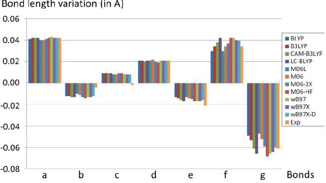
V.3.7. Scaling factors vs linear correction 146
V.3.8. Evaluation of the DFT functionals 147
iv
V.4. Conclusion 152
V.5. References 155
Chapter VI: Characterization of reduced metal complexes
159VI.1. Introduction 161
VI.2. Proof of concept 162
VI.2.1. manuscript 163
VI.2.2. Supporting Information 170
VI.3. Extension of the study to other complexes 173
VI.3.1. [ZnL]•+ type complexes (L= bidentate ligand) 173
VI.3.2. [ZnL']•+ type complexes (L'= tridentate ligand) 177
VI.3.3. [Zn(L1)(L2)]•+ type complexes (L1, L2 = bidentate ligands) 181
VI.3.4. [Ru(L1)(L2)]•+ type complexes (L1, L2 = bidentate ligands) 190
VI.4. Conclusion 194
VI.5. References 197
General Conclusions and Prospectives
2011
Chapter I
3
Introduction Générale (in French)
Développer un nouvel outil analytique pour l’aide à la conception de catalyseurs organométalliques plus efficaces représente un défi majeur aux applications très nombreuses. Pendant longtemps, les procédés en catalyse organométallique homogène étaient essentiellement basés sur les coûteux métaux dits « nobles » tels que le platine, le palladium et le rhodium. Ces métaux sont non seulement difficiles à obtenir en raison de leur faible abondance, mais leur approvisionnement ne peut être garanti à moyen terme. Leur production à partir de minerais pose de graves problèmes écologiques et leur prix varie énormément. Il est donc très important pour l'industrie chimique de pouvoir remplacer ces métaux par des métaux « communs » plus abondants et plus facilement accessibles tels que le zinc, le fer ou le cobalt. D’une manière plus générale, le développement d'approches plus « vertes » pour la catalyse, comme l'utilisation de la lumière visible en photocatalyse, est fortement recommandé.1
Les exceptionnelles performances obtenues en catalyse avec les métaux nobles résultent de la nature de leur états d’oxydation préférentiels, qui sont séparés de deux unités (Pd (0) / Pd (II) ; Rh (I) / Rh (III) ; etc…). Les processus chimiques de formation ou de rupture d’une liaison impliquant deux électrons, ces métaux sont donc particulièrement bien adaptés pour catalyser la formation et la rupture des liaisons. Les métaux communs, appartenant à la première ligne des métaux de transition dans le tableau périodique, ont à l’inverse des degrés d’oxydation préférentiels qui diffèrent d’une seule unité (Fe(II) / Fe (III) ; Co (II) / Co (III)). Contrairement aux métaux nobles, ces métaux de transition ne peuvent pas faciliter des processus classiques à deux électrons, à moins qu'un deuxième site ne soit prévu pour stocker ou donner un second électron. Des recherches récentes ont montré que des ligands « non innocents », tels que les ligands bis(imino)pyridines2 et terpyridines,3 peuvent accepter ce
4
second électron, et ces ligands ont été utilisés dans diverses réactions catalysées par des complexes à base de fer ou de cobalt.4 Ces systèmes moléculaires ont été étudiés en détails par un large éventail de techniques, mais leur instabilité en solution et leur très faible concentration, de surcroit au sein d’un mélange complexe dans lequel de nombreux radicaux sont potentiellement présents, rend extrèmement difficile leur étude et leur caractérisation à l’aide de nombreuses techniques expérimentales telles que la résonance magnétique nucléaire (RMN), la résonance paramagnétique électronique (RPE) ou la diffraction des rayons X. Cela signifie que la nature précise d'une grande partie de ces intermédiaires reste encore mal connue. Par exemple, l'implication d'états électroniques quasi-dégénérés dans l'un des systèmes les plus importants en catalyse au fer, le complexe [Fe(bis(imino)pyridine)], rend difficile la détermination de sa structure électronique5.
Les techniques de dissociation par capture d'électrons (ECD) et par transfert d'électrons (ETD) sont les méthodes les plus utilisées parmi l’ensemble des techniques utilisées en spectrométrie de masse et regroupées sous le terme générique de méthodes de dissociation activée par des électrons (ExD). Ce sont des techniques de fragmentation récentes qui ont montré un très fort potentiel pour l'analyse de peptides ou de protéines.6 En ECD et ETD, un polycation est partiellement réduit par un électron, c’est à dire qu'une espèce chimique dont l’état électronique est à couche fermée est transformée en un intermédiaire cationique à couche ouverte, ce dernier subissant une fragmentation.7
Le (ou les) mécanisme(s) exact(s) impliqué(s) dans un tel processus est(sont) encore source de nombreuses questions et discussions dans la littérature, et une meilleure compréhension de ces mécanismes s’avère nécessaire pour utiliser au mieux ces techniques dans de nombreuses applications.8 Une des principales questions non encore résolue est de connaître le site
ML
nm+[ML
n(m-1)+•
]
5
d’attachement de l'électron ajouté, ce qui permettrait de mieux comprendre la nature des fragments observés. Une autre question est liée à la question précédente: est-il possible d’obtenir une description appropriée, et en un temps raisonnable, de la structure électronique de ces cations radicaux à partir des méthodes actuelles de chimie théorique ?9
La question fondamentale du site de résidence de l’électron ajouté dans un processus de réduction électronique se pose non seulement pour les protéines et les peptides (les molécules étudiées le plus fréquemment par les techniques ExD), mais aussi pour les complexes organométalliques. Pour ces composés, l'électron ajouté peut être sur le centre métallique, sur un ligand ou un groupe chimique spécifique d'un ligand, ou bien il peut également être partagé entre ces différents sites. Cette question fondamentale peut avoir des implications importantes dans le sens où la connaissance et la compréhension précise de la structure électronique des espèces chimiques le long d'un processus catalytique facilitent son amélioration, permettant ainsi une conception rationnelle de nouveaux ligands et de nouveaux composés organométalliques possédant les propriétés structurales et électroniques adaptées. Ceci est tout particulièrement approprié pour les complexes organométalliques possédant des ligands non-innocents. En effet, la capacité des ligands non-innocents (ou ligands redox) à piéger et/ou à fournir un ou des électrons au centre métallique des complexes organométalliques leur confère un intérêt chimique incontestable, et ce type de complexes a démontré sa pertinence dans le développement de nouvelles méthodologies de synthèse. Ceci est parfaitement illustré par les complexes de métaux de base tels que Fe ou Cu, complexes qui sont alors bien adaptés pour participer à des procédés catalytiques pour lesquels deux électrons sont nécessaires, ceci étant rendu possible par la participation rédox de leurs ligands.10 Pour de tels procédés, il est donc fondamental de comprendre la structure électronique du complexe métal-ligand pour donner un aperçu de leur activité catalytique.11
6
Dans ce contexte, notre travail a consisté à développer une nouvelle méthode analytique pour les complexes organométalliques permettant de (i) produire des complexes organométalliques réduits en phase gazeuse, et (ii) caractériser leur structure électronique en combinant approches expérimentales et théoriques. L’objectif était de mettre en place une nouvelle méthode notamment pour distinguer entre la réduction du métal et la réduction des ligands pendant le processus catalytique.
Après cette introduction générale (chapitre I), le chapitre II décrit le fond méthodologique et théorique utilisé dans le cadre de cette thèse. Cela concerne les instruments expérimentaux ainsi que les méthodes de calcul.
Le chapitre III traite de la formation d'ions à charges multiples en phase gazeuse et de leur réduction électronique avec les méthodes d’activation par des électrons telles que la dissociation par capture d'électrons et la dissociation par transfert d'électrons.
Le quatrième chapitre explore l’aptitude des méthodes de calcul, et en particulier de nombreuses fonctionnelles développées dans le cadre de la théorie de la fonctionnelle de la densité (DFT), à déterminer la structure électronique de composés organométalliques réduites formés dans le chapitre précédent.
Dans le chapitre V, nous avons évalué la précision des fonctionnelles de la DFT, et en particulier les fonctionnelles hybrides à séparation de portée qui se sont révélées très pertinentes pour décrire la structure électronique au chapitre IV, pour reproduire les spectres infrarouges. Nous avons de plus déterminé et quantifié leur marge d'erreur.
Dans le dernier chapitre (chapitre VI), à l'aide des connaissances accumulées dans les chapitres précédents, nous avons détaillé la caractérisation de onze complexes radicalaires de zinc et de ruthénium en combinant les approches expérimentales et théoriques.
7
References
[1]. T. P. Yoon, M. A. Ischay, J. Du, Nat. Chem. 2010, 2, 527–532.
[2]. D. Enright, S. Gambarotta, G. P. A. Yap, P. H. M. Budzelaar, Angew. Chem. Int. Ed.
2002, 41, 3873–3876.
[3]. A. M. Tondreau, C. C. H. Atienza, J. M. Darmon, C. Milsmann, H. M. Hoyt, K. J. Weller, S. A. Nye, K. M. Lewis, J. Boyer, J. G. P. Delis, E. Lobovsky, P. J. Chirik
Organometallics 2012, 31, 4886–4893.
[4]. (a) K. T. Sylvester, P. J. Chirik J. Am. Chem. Soc. 2009, 131, 8772–8774; (b) A. M. Tondreau, C. Milsmann, A. D. Patrick, H. M. Hoyt, E. Lobkovsky, K. Wieghardt, P. J. Chirik
J. Am. Chem. Soc. 2010, 132, 15046–15059.
[5]. (a) A. M. Tondreau, S. C. E. Stieber, C. Milsmann, E. Lobkovsky, T. Weyhermüller, S. P. Semproni, P. J. Chirik, Inorg. Chem. 2013, 52, 635–646; (b) J. M. Darmon, Z. R. Turner, E. Lobovsky, P. J. Chirik, Inorg. Chem. 2012, 31, 2275–2285.
[6]. (a) L. M. Mikesh, B. Ueberheide, A. Chi, J. C. Coon, J. E. P. Syka, J. Shabanowitz, D. F. Hunt, Biochim. Biophys. Acta, 2006, 1764, 1811–1822; (b) H. J. Cooper, K. Hakansson, A. G. Marshall Mass Spectrom. Rev. 2005, 24, 201–222.
[7]. (a) J. Simons Chem. Phys. Lett. 2010, 484, 81–95; (b) F. Turecek, R. R. Julian Chem.
Rev. 2013, 113, 6691–6733.
[8]. (a) I. Swierszcz, P. Skurski, J. Simons J. Phys. Chem. A, 2012, 116, 1828–1837; (b) S. Maclot, J. Rangama, S. B. Nielsen, J. C. Poully Int. J. Mass Spectrom. 2013, 337, 1–11; (c) M. D. Wodrich, K. O. Zhurov, A. Vorobyev, H. Ben Hamidane, C. Corminboeuf, Y. O. Tsybin J. Phys. Chem. B, 2012, 116, 10807–10815 ; (d) F. Turecek, T. W. Chung, C. L. Moss, J. A. Wyer, A. Ehlerding, A. I. S. Holm, H. Zettergren, S. B. Nielsen, P. Hvelplund, J. Chamot-Rooke, B. Bythell, B. Paizs J. Am. Chem. Soc., 2010, 132, 10728–10740.
[9]. A. I. Gilson, G. van der Rest, J. Chamot-Rooke, W. Kurlancheek, M.Head-Gordon, D. Jacquemin, G. Frison J. Phys. Chem. Lett. 2011, 2, 1426–1431.
[10]. (a) S. Blanchard, E. Derat, M. Desage-El Murr, L. Fensterbank, M. Malacria, V. Mouriès-Mansuy Eur. J. Inorg. Chem. 2012, 376–389 ; (b) O. R. Luca, R. H. Crabtree Chem.
Soc. Rev. 2013, 42, 1440–1459.
9
General Introduction (in English)
Developing a new analytical tool for building efficient catalysts with transition metals that has immense potential of applications throughout the homogeneous catalysis is a relevant but challenging task. For a long time, reported processes in homogeneous organometallic catalysis were exclusively based on using the expensive precious metals such as platinum, palladium and rhodium. These metals are not only difficult to obtain due to their low abundance, but also their supplies will probably be exhausted in the medium term. Their production from ores is environmentally catastrophic and their price varies wildly. Therefore, it is very important for the chemical industry to replace these expensive metals with more abundant and easily obtained “base” metals such as zinc, iron or cobalt. In a more general way, developing greener approaches for catalysis, such as the use of visible light in photocatalysis, is highly recommended.1
The exceptional catalytic competence of the precious metals arises from the nature of their preferred oxidation states, which generally are separated by two electrons (Pd(0)/Pd(II); Rh(I)/Rh(III); etc). As the bond-making and breaking processes involved two electrons, these metals are uniquely well adapted to catalyze bonds formation and cleavage. The base metals, from the first row elements, which should ideally replace the precious metals, have preferred oxidation levels that are separated by only one electron such as (Fe(II)/Fe(III) and Co(II)/Co(III)). Unlike noble metals, these transition metals cannot easily support classical two-electron processes unless a second site is provided for storing or delivering an electron. Recent research has shown that ‘non-innocent’ ligands such as bis(imino)pyridines2
and terpyridines,3 can accept this second electron and these ligands have been used to assist iron and cobalt centers in various catalytic reactions.4 These systems have been studied extensively by a wide range of techniques, but their instabilities in solution, their often low concentration in mixture, their complexities and the electron-separated nature of their
10
intermediates rule out analysis not only by diamagnetic-friendly techniques such as NMR, but also by other techniques such as X-ray analysis and EPR. It means that the precise nature of many of the catalytic species or intermediate remains in doubt. For instance, the involvement of near-degenerate electronic states in one of the most important [Fe(bis(imino)pyridine)] systems make the determination of the electronics of the system particularly difficult to delineate.5
The Electron Capture and Electron Transfer Dissociation (ECD/ETD) techniques are the most used methods among the Electron activated Dissociation (ExD) techniques in mass spectrometry. They provide new fragmentation techniques that have shown a profound potential for the analysis of peptides or proteins.6 In ECD and ETD, a multiply charged cation is partially reduced by receiving an electron, thereby going from a closed-shell species to an intermediate cation-radical that undergoes fragmentation.7
The exact mechanism(s) implicated in such a process are still a matter of active discussion and a better understanding of them is required to expertise their applications.8 One main issue is to know the location of the added electron in order to be able to answer the question of the nature of the observed fragments. Another issue is related to this former question: how can a proper and time-efficient description of the electronic structure of such radical cations be obtained from theoretical chemistry methods ?9
The fundamental question of the residence site of an added electron in an electronic reduction process arises not only for proteins and peptides (the molecules most frequently studied by ExD techniques), but also for organometallic complexes. For these compounds, the added electron can be on metal, on a ligand or a specific chemical group of a ligand or it can also be
ML
nm+[ML
n(m-1)+•
]
11
shared by multiple ligands or between ligands and metal. This fundamental question may have important implications in the sense that the knowledge and understanding of the electronic structure of the species along a catalytic process facilitate its improvement by a rational design of new ligands and organometallic compounds able to tune the reactive properties. This is particularly true for organometallic complexes with non-innocent ligands. The ability of non-innocent (or redox) ligands to delocalize and/or provide electrons to the metal center of organometallic complexes confers them an undisputable chemical interest, and they have proved their valuables in the development of novel synthetic methodologies. This is especially well exemplified in the way that typical base metals, like Fe or Cu, can be adapted to participate in catalytic processes for which two electrons are required by means of a redox participation from their ligands.10 For such processes, it is thus fundamental to understand the electronic structure of the metal-ligand complex to provide insights into their catalytic activity.11
From this background, we worked to develop a new analytical method for organometallic complexes, that is (i) to produce electron reduced organometallic complexes in the gas phase, and (ii) to characterize their electronic structure with combined experimental and theoretical techniques. This will allow setting up a novel method to distinguish between metal reduction and ligand reduction during catalytic process.
After this introduction (Chapter I), Chapter II is used to describe the methodological and theoretical background used along this thesis. This concerns experimental instruments as well as computational methods.
Chapter III deals with formation of multiply-charged ions in the gas phase and their electronic reduction with electron activated methods such as electron capture dissociation and electron transfer dissociation.
12
The fourth chapter explores the ability of calculations, using various density functional theory methods, to determine electronic structure of typical reduced organometallic metal species formed in the previous chapter.
In chapter V, we assessed the ability of DFT functionals, in particular range-separated hybrid functionals which seems to perform well for the electronic structure as observed in chapter IV, to properly reproduce the infrared spectra, and we have established and quantified their error margin.
In the final chapter VI, using knowledge accumulated in previous chapters, we detailed the characterization of open-shell radical species with eleven specific examples of zinc and ruthenium complexes.
13
I.1. References
[1]. T. P. Yoon, M. A. Ischay, J. Du, Nat. Chem. 2010, 2, 527–532.
[2]. D. Enright, S. Gambarotta, G. P. A. Yap, P. H. M. Budzelaar, Angew. Chem. Int. Ed.
2002, 41, 3873–3876.
[3]. A. M. Tondreau, C. C. H. Atienza, J. M. Darmon, C. Milsmann, H. M. Hoyt, K. J. Weller, S. A. Nye, K. M. Lewis, J. Boyer, J. G. P. Delis, E. Lobovsky, P. J. Chirik
Organometallics 2012, 31, 4886–4893.
[4]. (a) K. T. Sylvester, P. J. Chirik J. Am. Chem. Soc. 2009, 131, 8772–8774; (b) A. M. Tondreau, C. Milsmann, A. D. Patrick, H. M. Hoyt, E. Lobkovsky, K. Wieghardt, P. J. Chirik
J. Am. Chem. Soc. 2010, 132, 15046–15059.
[5]. (a) A. M. Tondreau, S. C. E. Stieber, C. Milsmann, E. Lobkovsky, T. Weyhermüller, S. P. Semproni, P. J. Chirik, Inorg. Chem. 2013, 52, 635–646; (b) J. M. Darmon, Z. R. Turner, E. Lobovsky, P. J. Chirik, Inorg. Chem. 2012, 31, 2275–2285.
[6]. (a) L. M. Mikesh, B. Ueberheide, A. Chi, J. C. Coon, J. E. P. Syka, J. Shabanowitz, D. F. Hunt, Biochim. Biophys. Acta, 2006, 1764, 1811–1822; (b) H. J. Cooper, K. Hakansson, A. G. Marshall Mass Spectrom. Rev. 2005, 24, 201–222.
[7]. (a) J. Simons Chem. Phys. Lett. 2010, 484, 81–95; (b) F. Turecek, R. R. Julian Chem.
Rev. 2013, 113, 6691–6733.
[8]. (a) I. Swierszcz, P. Skurski, J. Simons J. Phys. Chem. A, 2012, 116, 1828–1837; (b) S. Maclot, J. Rangama, S. B. Nielsen, J. C. Poully Int. J. Mass Spectrom. 2013, 337, 1–11; (c) M. D. Wodrich, K. O. Zhurov, A. Vorobyev, H. Ben Hamidane, C. Corminboeuf, Y. O. Tsybin J. Phys. Chem. B, 2012, 116, 10807–10815 ; (d) F. Turecek, T. W. Chung, C. L. Moss, J. A. Wyer, A. Ehlerding, A. I. S. Holm, H. Zettergren, S. B. Nielsen, P. Hvelplund, J. Chamot-Rooke, B. Bythell, B. Paizs J. Am. Chem. Soc., 2010, 132, 10728–10740.
[9]. A. I. Gilson, G. van der Rest, J. Chamot-Rooke, W. Kurlancheek, M.Head-Gordon, D. Jacquemin, G. Frison J. Phys. Chem. Lett. 2011, 2, 1426–1431.
[10]. (a) S. Blanchard, E. Derat, M. Desage-El Murr, L. Fensterbank, M. Malacria, V. Mouriès-Mansuy Eur. J. Inorg. Chem. 2012, 376–389 ; (b) O. R. Luca, R. H. Crabtree Chem.
Soc. Rev. 2013, 42, 1440–1459.
15
Chapter II
Methodology
17
Part A: Experimental Methodology
IIA.1. Introduction
In this chapter, we described the theoretical background of computational calculations, methodology and instruments used for performing the IR spectroscopy of mass-selected ions. The aim of the thesis is to provide an analytical tool for characterizing the electronic structure of reduced metal ions in the gas phase via combination of mass spectrometry, infrared spectroscopy and DFT calculations.
In general, the organometallic complexes have been studied extensively for the purpose of homogeneous catalysis by utilizing the expensive noble metals such as platinum, palladium and rhodium. These metals are not only difficult to obtain with their abundance, but also their supplies will probably be exhausted in the medium term. Their production from ores is environmentally catastrophic. Therefore, for past few years, it has been a keen interest to replace these expensive metals with more abundant and easily obtained “base” metals such as zinc, iron or cobalt.
However, the utilization of these "base" metals in catalysis requires high redox properties of the ligands. Nevertheless, the experimental methods such as NMR, EPR, cyclic voltammetry and UV/Vis spectroscopy could not provide sufficient information in the solution phase at the molecular level. However, it is also very difficult to analyze when a species presents in the mixture of ions, having low concentrated solution and/or ion is unstable. Focused on this prospect, we aimed to develop an analytical tool to study transition organometallic complexes containing non-innocent ligands in the gas phase with the combination of spectroscopic techniques and computational calculations.
18
Experimentally, the idea is to selectively isolate the ions of interest using mass spectrometry, then to reduce these ions with the available fragmentations techniques, and further to irradiate them with infrared light. Different instrumental approaches have been developed and works have been reported on photodissociation of trapped ions in mass spectrometer.1,2 Methods such as Linear or quadrupolar radio-frequency ion-traps as well as Penning ion traps have been used, and many recent developments have been aimed at trapping ions at low temperature.
Particularly, the tandem mass spectrometer, installed at Centre Laser Infrarouge d’Orsay (CLIO) is coupled with two tunable infrared lasers and an auxiliary CO2 laser. The first laser
is the Free Electron Laser of the CLIO and is tunable in the mid-infrared from ~100 to ~2000 cm-1. It is routinely used to derive IR spectra of gas-phase ions in the 800-2000 cm-1 range. The second tunable infrared laser is a tabletop Optical Parametric Oscillator/Amplifier (OPO/OPA) laser. It is efficiently tunable in the 2500-4000 cm-1 near-infrared spectral range, which is useful for characterizing the NH and OH stretching modes, and in particular their spectral shifts which are characteristic of hydrogen bonding motifs.
An important factor to convince people of using IR activation for analytical purpose is the irradiation time. When using the IR Free Electron Laser, the irradiation time is typically of the order of few 100 ms. Tabletop laser is less powerful in comparison with the Free Electron Lasers and the irradiation time may have to be increased up to 1s depending on the dissociation energy threshold of the molecular ion. In this case, an auxiliary CO2 laser can be
19
IIA.2. Tandem Mass Spectrometry
IIA.2.1. General View
Tandem mass spectrometry (MS/MS) is a powerful analytical technique used to quantify known materials and to identify unknown compounds within a sample. The complete process involves the conversion of the sample into gaseous ions, with or without fragmentation, which are then characterized by their mass to charge ratios (m/z) and relative abundances.
Our experimental set-ups are based on two commercial tandem mass spectrometers; both of them are equipped with an Electrospray Source Ionization (ESI). One instrument, a Bruker SolariX is based on 9.4 Tesla at our laboratory, Laboratoire de Chimie Moléculaire (LCM), Ecole Polytechnique, which we used for our preliminary studies as this instrument facilitated with electron capture dissociation (ECD) and electron transfer dissociation (ETD), collision induced dissociation (CID) fragmentation techniques. The second instrument is from
Laboratoire de Chimie Physique (LCP), Orsay, is a Bruker Apex Qe, and is based on a 7 tesla
Fourier Transform Ion Cyclotron Resonance (FT-ICR) mass spectrometer. This instrument facilitated with CID and ECD techniques, and coupled with Infrared multi photon dissociation spectroscopy (IRMPD). CLIO has practical advantages for using commercial instruments. In the context of our work, the most important advantage is that CLIO provides a conventional way to perform the Electron capture dissociation (ECD) of mass-selected ions. This is particularly important for probing the structures of fragments for example, reactive intermediates involved in the peptide sequencing process. The following sections have been covered the detailed intrinsic technical aspects of the instruments that have been used for our research work.
20
IIA.2.2. FT‒ICR mass spectrometer set-up
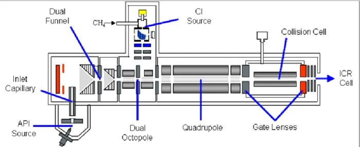
One of the mass spectrometers used during the thesis work is a hybrid 7 Tesla FT-ICR tandem mass spectrometer (Bruker, APEX Qe). It is called “hybrid” because there is a Quadrupole and hexapole (Qh) interface between the high pressure ion source region and the high vacuum region containing the ICR cell. The instrument is equipped with a conventional external electrospray ionization source (ESI). A scheme of the mass spectrometer which integrates the ICR is shown in Figure 1.1.
Figure 1.1: Schematic view of FT-ICR mass spectrometer (Bruker APEX Qe). The source, the Qh-unit (Quadrupole and hexapole), the transfer optics and the ICR cell are shown. The typical pressure of each region is specified in mbar.
The ESI source is the standard atmospheric pressure ion source for the measurement of singly charged samples such as benzodiazepines, and multiple charged samples such as proteins, peptides, and nucleic acids. The sample solution is introduced through the nebulizer assembly into the spray chamber, where it is subjected to the ESI process by means of an electrical field between the inner chamber wall and the spray shield, and with the aid of a nebulizer gas (N2).
21
The heated drying gas (N2) which flows in the opposite direction of the stream of droplets
enters in the spray chamber. Here, it's used to aid volatilization, then for the ionization, and later to carry away any uncharged material.
The continuous flows of electrosprayed ions is guided through Qh towards the ICR where ion manipulation takes place, and then before ions are sequentially ejected towards a conventional electron multiplier detector. This Qh interface consists of a linear quadrupole for mass selection and a linear hexapole ion trap. The latter is fitted in a pressurized (~10-3 mbar of Argon) cell and its purpose is fourfold. Hence, a weak abundant species from a complex mixture can be mass-selected using the quadrupole, and then accumulated in the hexapole ion trap. Secondly, the thermalization of the ions is ensured through multiple collisions of the ions with the argon buffer gas. As a result, thermalized ions are injected in the high vacuum region of the ICR cell.3 This is important since only radioactive cooling could occur in this low pressure region. Eventually, ion-molecule reactions can also be performed between the trapped ions and neutral seeded in the Argon line.
The third component of the mass spectrometer is the Ion Cyclotron Resonance (ICR) cell which is located in the ultra-high vacuum part of the instrument. The pressure in this part is routinely of the order of ~5.10-10 mbar in the instrument used. These low pressure conditions have to be maintained in order to minimize ion-molecule collisions which would perturb the trajectory of the ions and in turn the ion detection.
The first FT-ICR experiment was performed by Comisarow and Marshall in the 70’s, based on earlier developments in the 1930’s.4
Since then, significant improvements have been made, especially in terms of resolution and mass range.5
The basis of ion cyclotron motion is derived from the interaction of an ion with a spatially uniform magnetic field. An ion of charge q, and mass m, moving in a magnetic field B, will
22
experience a magnetic Lorentz force F that is perpendicular to both the direction of the ion velocity v, and the magnetic field (Equation 1.1).
Figure 1.2. The path of a positive ion moving at a constant velocity in a magnetic field is bent into a circle by the Lorentz magnetic force. The z-direction is defined as the vector pointing into the plane of the page.
= mass acceleration =
= ×
(1.1)As a consequence of this force, the ion path will bend into a circle of radius r in the plane perpendicular to the magnetic field (Figure 1.2). The Lorentz magnetic force is equal to the product of the ion mass and the angular acceleration in the xy plane, I / I = 2 , resulting in
Equation 1.2.
=
xy
B
(1.2)By substitution of the angular velocity about the z-axis, = xy/ , Equation 1.2 becomes
Equation 1.3, which can be rearranged to give the equation for ion cyclotron motion (Equation 1.4), where ωc is the cyclotron frequency.
2
=
(1.3)
c=
23
Thus, the motion of the ion within an ICR is dependent only on an ions m/z and the strength of the magnetic field, which is kept constant for FT-ICR. It is independent of the initial kinetic energy from ion formation or transfer, which means that translational focusing is not required for precise determination of m/z.6 The magnetic field of FT-ICR mass spectrometer used is 7.4 Tesla, It allows for a high mass resolution which is proportional to magnetic field strength. Ion manipulation, including trapping, mass-selection, ejection, and mass-analysis, is essentially based on the cyclotron motion. The working principle of ion detection is illustrated in Figure 1.3. Different configurations have been proposed for the ICR cell, and the Bruker infinity cell has a cylindrical shape, made of two sets of electrodes or plates: two “detection plates” and two “excitation plates”. Due to the cyclotron motion of the charged particles, an alternative image current can be detected on the two detection plates (Figure 1.3). For this purpose, ions are excited to a large cyclotron orbit radius using a resonant RF excitation voltage applied to “excitation electrodes”. In practice, a broadband frequency radio frequency (RF) signal is used for the excitation over a large frequency range (i.e. m/z range), and a transient image current is detected, which is a combination of the image current of all individual ions. Hence, the mass spectrum can be derived by Fourier transform of the image current, as proposed by Comisarow and Marshall in 1974.4 Mass selection in the ICR cell can be achieved using a dedicated broadband excitation signal in order to increase the orbital radius of all ions except for those with a given frequency (m/z) range. As a result all the non-desired ions are neutralized on the electrodes.
24
Figure 1.3: Detection and analysis of the ions in the ICR cell. The cyclotron orbit radius of the ions can be increased by applying an RF excitation on the “excitation plates”. An induced time-dependent image current can be detected on the “detection plates”. Mass spectrum can be derived using Fourier transform methods applied on transient image current
For performing IRMPD spectroscopy, the laser beam is mildly focused and aligned along the magnetic field axis. A detailed discussion of the ion-laser overlap issue is also provided, and the beam waist is of the order of one millimeter.7
The consequence on development of commercial analytical instrumentation demonstrated that ion-molecule reactions were not limited to FT-ICR-MS, but were also compatible with most modern mass analyzers; such as, ion trap,8 triple–quadrupole,9 quadrupole-TOF10 and orbitrap instruments.11
IIA.3. Fragmentation Techniques:
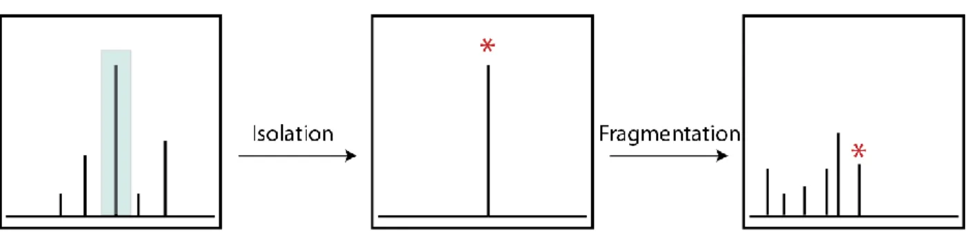
A typical MS/MS experiment, as illustrated in Figure 1.4, involves isolation of the desired precursor ion, characterized by a specific m/z, followed by activation and dissociation into product ions. The resulting product ions are then mass analyzed in the ICR cell. There are many different MS/MS techniques that have been developed over the years and each method
25
distinguished by the different modes of activation of the precursor ions and by the types of products that are formed.
Figure 1.4: A typical MS/MS experiment involves isolation of precursor ions, followed by fragmentation, and detection of fragment ions.
Searching for the most informative fragmentation patterns has led to the development of a vast array of activation modes that offer complementary ion reactivity and dissociation pathways. Collisional activation of ions using atoms, molecules or surface which results in unimolecular dissociation of activated ions, still plays a key role in tandem mass spectrometry. The discovery of electron activated dissociation methods, such as electron capture dissociation (ECD), electron transfer dissociation (ETD) and electron photo detachment dissociation (EPD) showed a significant impact, especially for structural analysis of large biomolecules. Similarly, photon activation opened promising new frontiers in the fragmentation of ion, owing to the ability of tightly controlled internal energy deposition and easy implementation on commercial instruments. Ion activation by photons includes slow heating methods such as infrared multiple photon dissociation (IRMPD) and black-body infrared radiative dissociation (BIRD) and methods like with high-energy photos ultra-violet photodissociation (UVPD).
26
IIA.3.1 Electron Capture Dissociation (ECD)
Electron capture dissociation (ECD) has been developed as an efficient ion fragmentation technique in tandem mass spectrometry (MS/MS). This was first described by Zubarev et al. in 199812 and has proved as a valuable MS/MS fragmentation technique for biomolecular analysis.13
In the instrumentation process of ECD, the ESI-produced multiply protonated ions for example peptides and proteins [M+nH]n+ capture a low-energy (<0.2eV) electron to produce the odd-electron ion [M+nH](n-1)+• which is not observable. However, it has been illustrated from literature that as odd-electron ion is accompanied by hydrogen loss, and forms [M+(n-1)H](n-1)+•.14 The mass of the reduced ion is essentially equal to that of the parent ion (differing by the mass of an electron), with a charge that has decreased by one. Consequently, it is essential that the precursor ions must be at least doubly charged, otherwise electron capture leads to neutral radical species which are undetectable via MS. Thus, the multi-charging capability of ESI makes the combination of ECD and ESI-FTICR-MS very desirable. ECD is a fragmentation technique and is more often used for analysis of post-translational modifications of proteins. It is also preferentially used for top-down analysis of proteins with size no larger than 35kDa. The principal of operation is shown in Figure 1.5 below. The electrons produced by the hollow cathode channel are pulsed into the ICR cell, which causes fragmentation of the ions (already trapped in the ICR cell). We performed ECD experiment on organometallic species with the mass spectrometers at our laboratory and at CLIO. Both of these instruments have been facilitated with the ECD fragmentation technique. The typical parameters of ECD in mass spectrometry at CLIO are as follows: The ECD pulse length of the electron beam can vary from 0.2 s to 0.001s with ECD bias (ionization energy of electrons) of
27
~1.0-3.0V. ECD lens parameter allows focusing of the electron beam and has a standard setting of ~15.0V, and ECD heater value of 1.6-1.8A.
Figure 1.5: Schematic representation of an electron injection system into an ICR cel for electron capture dissociation experiment.
Because of the concomitant charge reduction, the sensitivity of ECD-based MS/MS is lower than in traditional MS/MS. Furthermore, not all precursor ions should be allowed to capture electrons to avoid excessive neutralization of the fragments.15 The average ECD efficiency for peptides may vary about 20 to 50%, but can be higher for proteins.16
IIA.3.2. Electron Transfer Dissociation (ETD)
Electron-transfer dissociation (ETD) is also a method of fragmenting multiply-charged gaseous macromolecules in a mass spectrometer and introduced few years later than ECD.17 Similar to electron-capture dissociation, ETD induces fragmentation of large,
multiply-28
charged cations by transferring electrons to them.18 In particular, ETD is more often employed than ECD for peptide and protein structure analysis. The main reason is the implementation of efficient ETD MS/MS on relatively affordable, robust and widespread ion trap mass spectrometers, which deliver proteomics-grade performance, especially when coupled with high resolution mass analyzers, such as Orbitrap FTMS or time-of-flight TOF-MS.19 In contrast, ETD has received broad commercial implementation more on Fourier transform ion cyclotron resonance mass spectrometers (FT-ICR MS), which are powerful instruments, but are more complex to use and maintain.20
We were access to perform ETD experiments only in mass spectrometer at our laboratory and unfortunately, there is no availability of ETD technique in the mass spectrometry at CLIO, consequently, to study them further by IR spectroscopy. In principle, The ETD ion/ion reactions in the ESI-ETD instrument use a single reagent species and odd-electron anions are generated within a chemical ionization (CI) source mounted on the source octopole and transferred into the collision cell. These anions interact with multiply charged cations isolated in quadrupole, and after ETD fragmentation, the resulting multiply charged fragments and any remaining parent ions are transferred to the Ion Cyclotron Resonance (ICR) cell for detection. As shown in Figure 1.4, both the API and CI ion sources operate simultaneously. However, analyte and reagent ions are transferred consecutively. First, the multiply charged analyte cations are isolated and accumulated. During this period, the reagent anions from the CI source are blocked via the gate lens. For accumulation of reagent anions in the collision cell, the ion optics operate only partially in negative- ion mode. The API source is maintained in positive mode to ensure an undisturbed spraying process. Once reagent anions and multiply charged cations are trapped together in a combination of RF fields, the ion-ion reaction occurs as long as the reagent accumulation continues and for a defined reaction time. The resulting
29
multiply charged fragments and any remaining parent ions are then transferred to the ICR cell for detection.
Figure 1.6: A Schematic representation of an electron injection system into an ICR cel for electron capture dissociation experiment.
Overall, the major applications of electron activated dissociation methods such as ECD and ETD have been widely explored in the field of peptide and protein analysis such as the analysis of post-translational modifications including g-carboxyglutamic acid,21 N- and O-glycosylation,22,23 phosphorylation,24,25 and top-down sequencing. ECD has also been applied to protein folding analysis. Few studies have shown their use for cationized oligosaccharide26 and phosphocholine27 fragmentation, as well as for the generation of reduced cation species in water clusters28. Specifically, the utility of these fragmentation techniques have not explored of their necessity in the organometallic chemistry, Recently, Asakawa and coworkers have promptly used these electron dissociation methods for the description of Ni+2-, Cu+2- and Zn+2-polyhistidine oligomer complexes in the absence of remote protons.29 In this view, we motivated to use these techniques to study of electronic structure of our metal species presented in this thesis. Indeed, these electron activated methods have worked very efficiently to generate radical cationic complexes from dicationic complexes.
30
IIA.4. Infrared Multi-Photon Dissociation (IRMPD)
IIA.4.1. General View
The vibrational spectrum provides a wealth of structural information about an ion or a compound, such as on the location of charge (e.g. proton), the presence or absence of chemical moieties, its symmetry, and its hydrogen bonding interactions.
The first use of tunable lasers in combination with ion trapping approaches in mass spectrometry was in 1970’s, when Beauchamp and co-workers irradiated ions in the Penning trap of a Fourier transform ion cyclotron resonance (FT-ICR) mass spectrometer with the output from a line-tunable CO2 laser (925–1085 cm-1).30 Among gas discharge lasers in the
infrared, CO lasers are also useful, as they cover the 1600–1900 cm-1 range.31. These lasers were employed later in elegant laser spectroscopy studies on ions by Lee and co-workers. In their ‘‘messenger’’ technique, an inert atom (e.g. argon) or molecule (e.g. H2) is tagged to a
cold complex formed in a supersonic expansion, and is detached due to the absorption of a single infrared photon.32 The loss of the tag also results in a change in mass, which is detected by the mass analyzer. It took until the emergence of powerful and widely tunable free electron lasers (FELs) in 2000 to see a renaissance in IRMPD spectroscopy.
IIA.4.2. Principles
Since the beginning of mass spectrometry, gas-phase physical chemists have continuously showed a particular interest for the structures, energetics, and chemistry of gas phase ions. Infrared spectroscopy has long been considered a method of choice for structural characterization. IR absorption spectra are derived by monitoring the ratio between the transmitted infrared light (IT) and incident infrared light (I0). Such direct absorption
31
spectroscopy usually requires 1010 ion/cm3 or higher density number.33 Direct absorption spectroscopy is thus impossible in a Paul or in a Penning ion trap where the maximum number of ions is 106 ions, within a small volume (few mm3). Alternatively photon absorption can be probed by monitoring the IR induced fragmentation of the trapped ions. It is worth to say that dissociation threshold for typical molecular ions is of the order of 1 eV, i.e. an order of magnitude larger than that of an infrared photon. One immediately sees that multiple photons have to be absorbed in order to induce ion dissociation. This photon absorption is considered to proceed stepwise, and it is named “InfraRed Multi Photon Dissociation” (IRMPD).
Figure 1.3: Multiple Photon Absorption through a single IR active vibrational mode assuming that the potential is harmonic (left) or anharmonic (right).
The energy potential associated with the vibrational pumping mode is shown in Figure 1.7. This vibrational mode is called “resonant mode” or “pumping mode”, because the energy is pumped into the molecular ion through this vibrational mode. If the energy potential associated with this mode is assumed to be harmonic, multiple IR photons could be absorbed consecutively. Nevertheless, due to the anharmonicity of the potential, only few photons can be sequentially absorbed depending on the laser spectral width relative to the anharmonicity. This is often referred to the “anharmonic bottleneck”.
32
Figure 1.8 illustrates the general understanding of the non-coherent multiple photon absorption process. Assuming that the anharmonicity associated with the pumping mode is large compared to the width of the laser, only one photon could be resonantly absorbed by the pumping mode. Prior to the subsequent photon absorption, it is assumed that there is de-excitation (ν=1→0) of the pumping mode and redistribution of the internal energy into the other vibrational modes of the molecular ion. This diffusion of the energy is known as Intramolecular Vibrational Redistribution (IVR),34 and it is crucial for allowing subsequent photon absorptions. After partial or complete (i.e. statistical redistribution of the energy) IVR, the resonant mode can absorb another photon through the first vibrational transition (ν=0→1). The multiple photon absorption process can be seen as successive cycles involving IR absorption in the pumping mode followed by IVR. As a result, there is a stepwise increase of the internal energy of the ion as shown in the bottom panel of Figure 1.8.
Figure 1.8: Schematic representation of the multiple photon absorption process. It is assumed that as energy raise can be understood as successive cycles involving resonant one photon absorption (red arrows) and intramolecular vibrational energy redistribution (IVR, represented as arrows in blue). This can be represented using the vibrational energy levels of the “pumping mode” as a function of time as in the top panel. The evolution of total energy of the ion as a function of time is given in the bottom panel.
33
The nature of the absorption of multiple IR photons has been intensively discussed in the literature in the seventies.35 Highly intense lasers were used to investigate whether the fragmentation of neutral molecule could be isotopically selective or not. It was suggested that the multiple photon absorption mechanism proceeds through three steps, evolving with the density of vibrational states. The earlier steps of the process were supposed to follow a coherent multiphoton absorption process, and the laser peak power was shown to be critical.36 This coherent multiple absorption process was named “IR MultiPhoton Dissociation” (IRMPD).33 In order to make the distinction with this coherent IRMPD process, the incoherent IRMPD process at play in our case is thus named “IR multiple photon dissociation”.
The first attempt of modeling the multiple photon absorption process by a molecular system irradiated by an IR FEL was proposed by von Helden and coworkers.37 Gas phase neutral C60 was irradiated with the FELIX IR FEL and thermal emission of electrons was monitored. It was observed that the excitation was much more efficient when the IR radiation was chirped to lower frequencies during the macropulse. A model was used to understand these phenomena. More recently, Parneix and coworkers proposed a kinetic model of the energy absorption and distribution (IVR) during the macropulse of an IR FEL.38 All the steps including absorption, stimulated emission, spontaneous emission, and dissociation were taken into account. Monte Carlo simulations of the IRMPD process relied on anharmonic potential energy surfaces calculated using quantum chemical calculations.
IIA.4.3. IR-Free Electron Laser (FEL)
In 1976, the first paper was published that related to IR Free Electron Lasers (FEL) by the group of Smith at Stanford.39 They showed that amplification of infrared radiation of a CO2
34
transverse magnetic field called undulator. A year later, the same group showed that IR photons can be generated and amplified using free electrons passing through the undulator which was placed within an optical cavity.40 Indeed, photon emission relies on the deviation of the trajectory of quasi-relativistic electrons. The electrons beam was tuned at 24 MeV and an IR beam centered at 3.417 m with a width of 0.008 m and an average power of 360 mW was obtained. As stressed in the introduction, the electron medium is unique in the sense that it allows a wide tunability and constitutes at the same time the amplification medium.40 Nowadays, the FELs under operation produce Ultra Violet and Infrared up to far IR light. X-ray production is currently being developed.41
A schematic view of the Infrared FEL is provided in Figure 1.9. The trajectory of the electron beam is modified when it passes through the magnetic cavity or undulator, where the photon emission occurs. The IR FEL beam is then extracted through a hole in one of the cavity mirrors. The amplification and the coherence of the IR FEL beam is the subtle result of the interaction or the electrons and emitted light stored in the optical cavity. The wavelength of the IR FEL beam depends on the energy of the electrons and of the period and strength of the magnetic field.
Figure 1.9: Magnetic cavity of the CLIO IR FEL. Two magnetic benders (or electrostatic dipoles) are used to direct the electron beam (in black) into the undulator and extract it towards a beam dump at the exit of the undulator (north and south poles in violet and red, respectively). Under the influence of the alternative magnetic field, the quasi relativistic electrons bundle onto a snacking path which is at the origin of the photon emission. The interaction between the electrons and IR photons (yellow) beams is at the origin of the IR beam amplification.
35
The temporal structure of the IR FEL shown in Figure 1.10 is induced by that of the electron beam. The CLIO laser produces trains of IR pulses, called macropulses, at 25 Hz. These macropulses are composed of picosecond long pulses at 62.5 MHz. It should be noted that two consecutive picopulses are separated by 16 nanoseconds, which is the order of magnitude of the lifetime of excited vibrational state, typically ranges from picosecond to nanosecond.42 It is thus conceivable that there is enough time for IVR to proceed between two consecutive pico-pulses. The efficient noncoherent multiple photon absorption process observed with IR FEL may thus not only due to its high intensity, but also to its pulsed structure.43
For a given electron energy, continuous tunability can be obtained from to 2 with a relatively constant laser power. The laser mean power is routinely higher than 1 W which corresponds to macropulse (picopulse) energy of 40 mJ (80 J). The bandwidth of the IR FEL strongly depends on the laser cavity length. Bandwidth of 10-20 cm-1 in the 800-2000 cm-1 range is generally used.
Figure 1.10: Temporal structure of the CLIO IR FEL at Orsay. Trains of pulses (called macropulses) are delivered at 25 Hz as illustrated in the top of the Figure. Each individual macropulse is composed of ~1 pico-second pulses separated by 16 nanoseconds as illustrated in the bottom of the Figure
36
The operation of the FEL at CLIO started in 1991, and currently, J.-M. Ortega is the in charge of CLIO. Presently, the CLIO FEL is mainly used for IRMPD spectroscopy. The development towards long-wavelength is an important research topic. CLIO has an important characteristic, which could be used for two-photon IRMPD experiments: there are two independent undulators which allow for lasing simultaneously at two different wavelengths.44 Beside the IRMPD set-ups, there are two others: one uses the IR FEL for Second Harmonic Generation (SHG) experiments for probing adsorption phenomena on surfaces45 with applications in Electrochemistry.46 The second experimental set-up couples Atomic Force Microscopy (AFM) with IR CLIO FEL which provides another dimension to AFM. These methods have wide range of applications mainly forthe biological systems such as bacteria47 and phenomena at the sub-cellular level.48
In particular, free electron lasers (FELs) are uniquely placed to carry out IRMPD experiments, given their continuous and wide tunability, as well as high spectral brightness (i.e., peak power > 10 MW). Currently, there are three free electron lasers in the world where IRMPD experiments are routinely carried out: the Free Electron Laser for Infrared eXperiments (FELIX) near Utrecht in the Netherlands,49 the Centre Infrarouge Laser Orsay (CLIO)50 near Paris in France and FEL-SUT (Tokyo, Japan). Construction of a similar FEL is under way at the Fritz–Haber Institute (Berlin, Germany). FELIX and CLIO operate as user facilities.
37
IIA.5. Non-innocent ligands
IIA.5.1. General view
In catalytic system, ligand plays an important role by allowing fine-tuning of reactivity and selectivity through steric or electronic interactions all along the catalytic cycle. However, the optimization of a catalytic system often needs deeper and extensive structural modifications. To date, a ligand mostly known as well characterized closed-shell molecule that shows well defined tasks, and in this prospect, the less defined and intriguing electronic structure of non-innocent ligands (NILs) holds promises as to their use in innovative organometallic catalysis.51 Numerous non-innocent ligands are known at present and their numbers are increasing each year: new types of ligands are being synthesized and already known ligands are shown to be non-innocent.52 The word “non-innocent” was initially coined in 1966 in a seminal work done by Jorgensen53 stating that “ligands are innocent when they allow oxidation states of the central atom to be defined”, though the closer definition of what a NIL is not. This statement clearly indicates that NILs are essential molecular scaffolds that are capable to delocalize part of the electron density of the complexes to which they belong. The reasons for this are the higher energy HOMO or low-lying LUMO levels (excluding the lone pair that coordinates to the metal center) of these ligands as compared to those of typical ligands, and NILs will therefore participate in electronic transfer through bonding process.54 This specificity can enhance the scope of redox events that a metal can perform by overcoming the limitations imparted by its original electronic structure. Since their introduction in the field of organometallic chemistry, NILs and complexes thereof have attracted much attention, mainly devoted to the identification, extensive studies, and rationalization of their unusual electronic properties.55 However, NILs are now emerging as
38
synthetically useful and attractive scaffolds with broad and exciting perspectives as their uses could open up the field of reactivity of easily accessible base metals.
IIA.5.2. Structural evolution
Before we start to discuss the term “non-innocent ligand”, it is necessary to introduce two terms: formal oxidation state and physical or spectroscopic oxidation state. These two terms are, at first sight, very similar but not identical. The formal oxidation state of a given metal ion in a mononuclear coordination compound is commonly defined by “the charge remaining on the metal after all ligands have been removed in their normal, closed-shell configuration – that is with their electron pair”.56
For example, the formal oxidation state of the iron in a neutral [Fe(acac)3] (acac = acetylacetonato) is +3, because when calculating the formal oxidation state, one removes three acac ligands as usual in their closed-shell anionic form
leaving the charge +3 on the metal.
On the other hand, it is sometimes possible to determine the electronic configuration of the metal in the complex directly by various spectroscopic methods. To determine the oxidation state of the metal in iron complexes, for example, it is usual practice to apply 57Fe Mössbauer spectroscopy. By knowing the electronic configuration of the metal in the complex, one can immediately calculate the oxidation state of the metal ion. In 1969 Jörgensen suggested that the oxidation state of the metal ion, which is determined from its known electronic configuration, should be specified as the physical or the spectroscopic oxidation state.57 A Mössbauer spectrum recorded on [Fe(acac)3] confirms the physical oxidation state of iron to
39
Although both, the formal and the physical oxidation state of the iron in our example [Fe(acac)3] were shown to be the same, it is not always the case. In 1966 Balch and Holm
reported the reaction of nickel chloride with o-phenylenediamine in aqueous ammonia resulting in the formation of a neutral complex with the “brutto” formula [Ni(C6H4(NH)2)2].59
Which structure corresponds to the given “brutto” formula and which oxidation state has the metal in this complex ?
Let us first apply the rules for determining the formal oxidation state of the nickel. Two “classical” structures can be drawn for this complex,
Structure A comprises two o-benzoquinonediimine neutral ligands, while structure B consists of two o-phenylenediamido(2–) dianions. Both ligands are “normal” closed-shell ligands. After removing the ligands in their closed-shell form, we obtain the formal oxidation state of the nickel. For structure A, the formal oxidation state of the nickel is zero, while for structure
B we obtain the unusually high formal oxidation state +4 (?). Certainly we can speculate that
the complex contains two types of the ligand: one benzoquinonediimine and one o-phenylenediamido(2–), but several methods, including single crystal X-ray analysis,60 confirm that the two ligands are identical.
On the other hand, it was shown by various spectroscopic methods and DFT calculations that the electronic configuration of nickel in [Ni(C6H4(NH)2)2] and related complexes is d8 and
consequently, the physical oxidation state is +2.61 It is important to note that the formal

![Figure 3.4: Electron transfer dissociation FT-ICR mass spectrum of [Ru(1) 3 ] 2+ at m/z 285](https://thumb-eu.123doks.com/thumbv2/123doknet/2846037.70040/90.892.98.801.119.567/figure-electron-transfer-dissociation-ft-icr-mass-spectrum.webp)
![Figure 3.7 shows the ETD spectrum of [Zn(1) 2 (5)] 2+ (m/z 278). We observe the dissociation](https://thumb-eu.123doks.com/thumbv2/123doknet/2846037.70040/93.892.108.798.340.798/figure-shows-etd-spectrum-zn-m-observe-dissociation.webp)
![Figure 3.9: Electron transfer dissociation FT-ICR mass spectrum of [Zn(1)(5) 2 ] 2+ at m/z 290.](https://thumb-eu.123doks.com/thumbv2/123doknet/2846037.70040/95.892.109.795.109.543/figure-electron-transfer-dissociation-ft-icr-mass-spectrum.webp)
![Figure 3.10: Electron capture dissociation FT-ICR mass spectrum of [Zn(1)(5)] 2+ at m/z 200](https://thumb-eu.123doks.com/thumbv2/123doknet/2846037.70040/96.892.111.793.106.537/figure-electron-capture-dissociation-ft-icr-mass-spectrum.webp)
![Figure 3.11: Electron transfer dissociation FT-ICR mass spectrum of [Zn(1)(5)] 2+ at m/z 200](https://thumb-eu.123doks.com/thumbv2/123doknet/2846037.70040/97.892.105.793.109.569/figure-electron-transfer-dissociation-ft-icr-mass-spectrum.webp)