HAL Id: hal-02102259
https://hal-lara.archives-ouvertes.fr/hal-02102259
Submitted on 17 Apr 2019
HAL is a multi-disciplinary open access
archive for the deposit and dissemination of
sci-entific research documents, whether they are
pub-lished or not. The documents may come from
teaching and research institutions in France or
abroad, or from public or private research centers.
L’archive ouverte pluridisciplinaire HAL, est
destinée au dépôt et à la diffusion de documents
scientifiques de niveau recherche, publiés ou non,
émanant des établissements d’enseignement et de
recherche français ou étrangers, des laboratoires
publics ou privés.
Booting and porting Linux and uClinux on a new
platform
Nicolas Fournel, Antoine Fraboulet, Paul Feautrier
To cite this version:
Nicolas Fournel, Antoine Fraboulet, Paul Feautrier. Booting and porting Linux and uClinux on a new
platform. [Research Report] LIP RR-2006-08, Laboratoire de l’informatique du parallélisme. 2006,
2+26p. �hal-02102259�
Laboratoire de l’Informatique du Parallélisme
École Normale Supérieure de LyonUnité Mixte de Recherche CNRS-INRIA-ENS LYON-UCBL no5668
Booting and Porting Linux and uClinux on a new
platform
Nicolas Fournel
Antoine Fraboulet
Paul Feautrier
February 2006 Research Report NoRR2006-08École Normale Supérieure de Lyon
46 Allée d’Italie, 69364 Lyon Cedex 07, France Téléphone : +33(0)4.72.72.80.37 Télécopieur : +33(0)4.72.72.80.80 Adresse électronique :lip@ens-lyon.fr
Booting and Porting Linux and uClinux on a new platform
Nicolas Fournel
Antoine Fraboulet
Paul Feautrier
February 2006
AbstractThis research report presents a full case study on porting and booting the Linux and uCLinux operating system on a new platform. We present this work on the ARM Excalibur CM922TXA10 for which a new machine type has been created to be able to run the platform in a standalone mode.
Keywords: Linux, uCLinux, Operating System, ARM Platform, Porting
Résumé
Ce rapport de recherche présente une étude de cas complète sur les développement et l’adaptation des noyaux Linux et uCLinux pour une nouvelle machine. Le dévelop-pement est effectué sur l’adaptation des noyaux pour une machine ARM Integrator CM922TXA10 et permet de faire fonctionner cette dernière de façon autonome.
Contents
1 Introduction: knowing the hardware. 3
1.1 CM architecture . . . 4
1.1.1 Hardware architecture . . . 5
1.1.2 Interruption architecture and behavior . . . 6
1.1.3 Memory map . . . 6
1.2 CP architecture . . . 7
1.2.1 Hardware architecture . . . 7
1.2.2 Interruption architecture and behavior . . . 8
1.2.3 Memory map . . . 8 1.3 ARM 922T architecture. . . 9 1.3.1 Global architecture . . . 10 1.3.2 ARM9TDMI core . . . 10 1.3.3 Caches . . . 10 1.3.4 MMU/TLB . . . 10
2 Booting Linux on the platform 11 2.1 Boot loader . . . 12
2.2 Compiling and using the Linux kernel . . . 13
2.2.1 Linux and application compilation . . . 13
2.2.2 Linux root file system . . . 13
2.2.3 Firmware loading. . . 14
2.3 Compiling and using the uClinux kernel . . . 14
2.3.1 uClinux and applications compilation . . . 14
2.3.2 uClinux root file system . . . 15
3 Porting the Linux kernel on the CM922T-XA10 platform 15 3.1 Porting the boot loader . . . 15
3.2 Porting Linux . . . 16
3.2.1 Adding a new platform . . . 17
3.2.2 Deflation phase . . . 19
3.2.3 Linux kernel boot. . . 20
3.3 porting uClinux . . . 24
4 Conclusion 24
List of Figures
1 Integrator/CM922T-XA10 board . . . 3
2 Integrator/CP board . . . 4
3 Basic image architecture . . . 6
4 CM interrupt architecture . . . 7
5 CM 922T-XA10 memory map . . . 7
6 CP 922T-XA10 hardware architecture . . . 8
7 CP interruption management . . . 9
8 CP 922T-XA10 memory map. . . 9
9 ARM 922T architecture. . . 10
10 ARMv4 MMU level 1. . . 11
11 ARMv4 MMU level 2. . . 12
12 Global MMU access diagramm. . . 12
1
Introduction: knowing the hardware.
In this section we will give a rapid overview of the platform we will talk about in the next sections. This platform is an ARMTMdevelopment board, its name is ARM Integrator. The board can be divided into two
different parts.
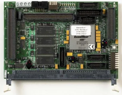
The first part of the platform is the Core Module, which explains its full name Integrator/CM. This part integrates the CPU and the main memory, as well as a FPGA and Flash memory (16 MB).
ARM has a large range of Core Modules, there exists almost one Core Module by ARM processor, nearly all these core modules have the same layout. Our Core Module is based on an ARM9, the ARM 922T. However there are two different core modules based on this processor. The first one is a basic core module with the common layout. The second is a little special, because it is based on an Altera Excalibur EPXA10, which is a PLD (Programmable Logic Device), or more precisely a FPGA (Field-Programmable Gate Array), integrating the processor. Our module is the second and its name is Integrator/CM 922T-XA10.
Figure 1: Integrator/CM922T-XA10 board
The core modules are designed to be used in conjunction with other platforms. For example it is possible to connect four core modules together and have them communicate by a special bus. Another application is to connect them to a baseboard, CP (Compact Platform) or AP (Application Platform). All these applications are made possible by the two connectors named HDRA and HDRB (Header A and B). These connectors are present on both sides of the board (HDRA on the left and HDRB on the right), and on both faces to allow stacking. An extra connector is available on the upper side of the board, its name is EXPIM, and its goal is to connect extension boards like FPGA-based ones.
These points are true for all core modules, but concerning CM 922T-XA10 an extra application is available, the standalone mode. In fact, the EPXA10 (the Altera FPGA) integrates a piece of silicon, a stripe, containing a CPU (ARM 922T) but a lot of peripherals too. For example, the stripe integrates two timers, an UART, a memory controller, and some other peripherals. With the peripherals embedded on the CM 922T-XA10 we can run a full operating system.
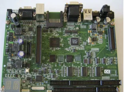
The second part of the platform is a baseboard. Its name is Integrator/CP, where CP stands for Compact
Platform. This part of the platform integrates a large number of peripherals that could be useful for an
embedded software developer. For example, there is 16 MB of Flash memory, which allow the user to load home brew applications and launch them on the platform. It also includes sound, network and MMC1 reader peripherals. However the CP board does not embed any processing unit nor main memory. In fact
it is designed to be connected to a core module. It can be connected with only one module at a time, but from any type, i.e. with any processor. As we mentioned before, all core modules are based on a processor, main memory and an FPGA. In the case of a CP connection (the CM mounted on a CP board), the control parts of peripherals are implemented in the FPGA of the core module. Indeed, only the remaining parts of the peripherals are implemented on the CP physically. These remaining parts, the physical interfaces, are available from their controllers through specific buses.
Finally, the CP fully integrates some peripherals, like a GPIO (General Purpose Input/Output), and these are accessible through a general purpose AHB2bus.
Figure 2: Integrator/CP board
The core module is connected to the compact platform by the two connectors mentioned before, HDRA and HDRB. In this configuration, the connectors carry power supplies, general purpose bus and other specific buses between the two parts.
1.1
CM architecture
As we explained before almost all ARM core modules have the same architecture. The CM 922T-XA10 has a compatible architecture, but as it is based on an Excalibur EPXA10[1], it has architectural specificities :
• All core modules integrates an ARM CPU, in the CM 922T-XA10, it is part of the EPXA10 stripe. • Core modules integrate SSRAM, with a SSRAM controller implemented in a PLD. The CM
922T-XA10 embeds SSRAM as well, but the SSRAM controller is implemented in the FPGA.
• Core modules integrate an FPGA in which peripherals are implemented. The EPXA10 is an FPGA,
so it is also true for the CM 922T-XA10.
• SDRAM main memory can be plugged in the DIMM slot on core modules, and the memory
con-troller is implemented in the FPGA. CM 922T-XA10 has 128MB of SDRAM memory on board and a hardware memory controller is available in the EPXA10. A DIMM slot is also available on the CM 922T-XA10.
On top of these variations on the common CM architecture, CM 922T-XA10 has special features not available on all core modules :
• EPXA10’s stripe embed a lot of basic peripherals like a serial controller, a memory controller, . . . • CM 922T-XA10 offers 16 MB of flash memory (for user applications). This feature is related to the
possibility of running the CM 922T-XA10 in a full standalone mode.
1.1.1 Hardware architecture
In this subsection we will give a detailed view of the hardware architecture of the core module CM 922T-XA10. In fact, the hardware can be divided into two parts, the real hardware and the FPGA-implemented hardware.
The first part is made of the stripe’s peripherals and the on board integrated chips, here is an exhaustive list :
• Stripe’s peripherals :
– CPU (ARM 922T) – memory controller – watchdog timer
– single and dual port SRAMs (SP/DP SRAM) – PLL (Phase-Locked Loop)
– reset logic – two timers
– UART (Universal Asynchronous Receiver-Transmitter) – EBI (Expansion Bus Interface)
• Onboard chips :
– SDRAM connected to the memory controller
– SSRAM connected to the FPGA-implemented memory controller – Flash memory connected to the EBI
– clock generators
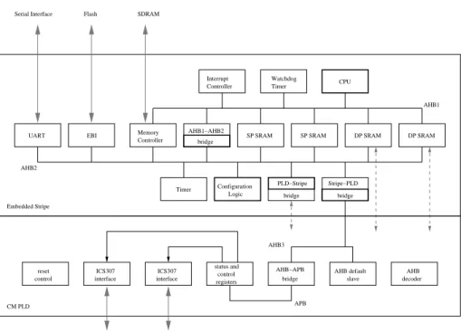
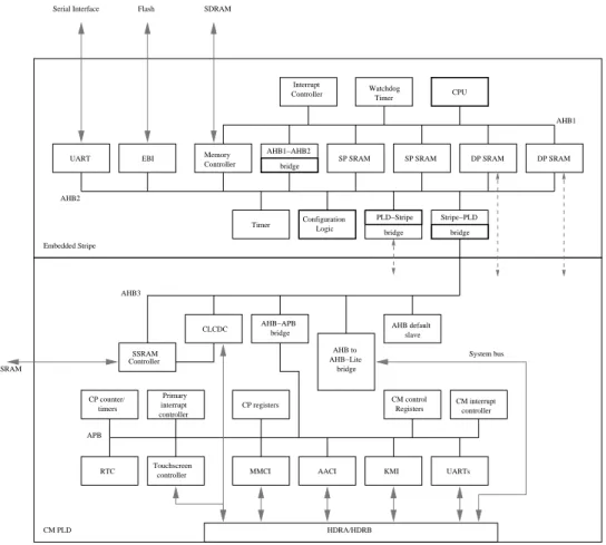
The second part is not fixed since it is implemented in the FPGA. Indeed, at the boot of the core module, the image to be loaded in the FPGA is selected according to switches or signal values. One of these images is especially designed to be used with the CP, another to be used with an AP or in standalone mode. The last and simplest one is designed for standalone mode, the basic image. We will take the last one to give an overview of the full hardware architecture of the CM922T-XA10 in standalone mode. In this image only few peripherals are implemented in the FPGA. In fact, only two interfaces are implemented to control the clock generators chips, as well as control and status registers. The global architecture is depicted in figure
3.
As far as interconnections are concerned, one can see from this diagram that the peripherals are acces-sible by three different AHB busses. The stripe of the EPXA10 already contains two AHB buses connected by a bridge (AHB1 and AHB2 on figure3). A third AHB bus (AHB3 on figure3) is implemented in the FPGA, this one is also connected to the others through another bridge, a bridge between stripe and PLD (from stripe to PLD).
In this image we must underline that the SSRAM is not used since no SSRAM memory controller is implemented in the FPGA. The second bridge between stripe and PLD (from PLD to stripe) and the second ports of the DPSRAMs are not used either.
UART Memory Controller status and control registers ICS307 interface ICS307 interface AHB−APB bridge AHB default slave reset control AHB decoder Interrupt Controller Logic Configuration DP SRAM DP SRAM SP SRAM SP SRAM SDRAM Flash Serial Interface Watchdog Timer Embedded Stripe Timer CPU AHB2 AHB1 EBI CM PLD APB AHB3 AHB1−AHB2 bridge PLD−Stripe bridge Stripe−PLD bridge
Figure 3: Basic image architecture. Bold blocks are bus masters
1.1.2 Interruption architecture and behavior
With the basic image, the CM 922T-XA10 only integrates one interrupt controller linked directly to the CPU exception wires.
Before describing the behavior of this interruption controller, we will give a few details about ARM exception management. Interruptions and fast interruptions are two of the six exceptions handled by ARM processors. The six exceptions are reset, prefetch, aborts, undefined instructions, interruptions, fast inter-ruptions, and software interruptions. The management of exceptions is the same regardless of their type. If an exception is raised, the CPU jumps to the exception handler address. This address is calculated as the sum of the exception base address, which can be either0x00000000or0xFFFF0000depending on the configuration of the processor, plus an offset given by the type of exception, for example interruption request offset is0x18. The instruction fetched at this address is most of the time a jump to the address of the full exception handler implemented by the developer.
As we can realize from the previous list, hardware interrupts can be handled by two different exceptions. These two levels of interruption are : interruption request (IRQ) and fast interruption request (FIQ).
On CM922T-XA10 programmed with basic image, all hardware interruptions are gathered by one inter-ruption controller linked to the two interinter-ruption exception wires of the CPU. Each peripheral is connected to this interruption controller (ITC) by only one wire. Thus the ITC raises either an IRQ or a FIQ, according to the interruption priority. The highest level of priority (0x3F) corresponds to a fast interruption.
1.1.3 Memory map
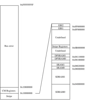
All stripe peripherals are controlled by registers mapped to memory. These registers are regrouped in a register bank, the stripe register bank. The default mapping address of this bank is0x0B000000. Another control and status register bank corresponding to the CM peripherals is mapped at0x10000000.
The remainder of the memory map contains memories mapping (Flash, SDRAM, SPSRAM and DP-SRAM). Figure5gives a full overview of this memory map.
0 1 2 3 4 5 6 8 11 7 9 10 PLLINT TIMERINT0 UARTINT EXTINT INT_PLD5 INT_PLD4 INT_PLD3 INT_PLD2 INT_PLD1 INT_PLD0 EBIINT 14 15 16 S2PLDINT AHB12INT COMMRX FASTCOMMSINT 13 COMMTX TIMERINT1 12 31:17 Reserved Name Bits Stripe ITC
ARM core INT_nIRQ INT_nFIQ
Figure 4: CM interrupt architecture
0x10000000 0x08000000 SDRAM0 SDRAM1 SRAM0 SRAM1 DPSRAM0 DPSRAM1 Undefined EBI1 EBI2 Undefined 0x08100000 0x08110000 0x0B000000 0x0F000000 0x04000000 0x08020000 0x0F800000 0x10800000 0xFFFFFFFF Stripe CM Registers
Bus error Stripe Registers
Figure 5: CM 922T-XA10 memory map
1.2
CP architecture
As mentioned earlier, a specific image must be loaded in the FPGA to take advantage of the compact platform (CP). The combination CP plus CM 922T-XA10 is called CP 922T-XA10 in the literature.
Connecting the CM to a compact platform offers the developer more peripherals. These additional peripherals are the following : a sound device, a video device, a network device, storage devices (Flash memory and MMC card reader), . . .
Most of the peripherals of the CP are in fact implemented in the FPGA of the core module, as well as a AHB-bridge, allowing other peripherals to be connected.
1.2.1 Hardware architecture
We will show here that the CP 922T-XA10 architecture is only an extension of the CM 922T-XA10 one. The only difference in terms of hardware architecture between these two platforms are the peripherals implemented in the FPGA. Thus, the stripe’s peripherals are always available. In the CP 922T-XA10 we find almost all peripherals of the CP implemented in the FPGA. The CM control and status registers are always implemented in it, but the clock generators interfaces are not available any more, because they are
used for the implementation of the CP peripherals.
The FPGA implements two extra level of interconnections. The first is an APB (Advanced Peripheral Bus) on which FPGA-implemented peripherals are connected. The second is an AHB-Lite also called system bus on which peripheral fully implemented on the compact platform are connected, for example the GPIO (General Purpose Input/Output) and the Ethernet device.
UART Memory Controller Logic Configuration SSRAM Controller AHB−APB bridge AHB to AHB−Lite bridge controller CM interrupt CM control Registers Touchscreen controller Primary interrupt controller timers CP counter/ slave AHB default DP SRAM DP SRAM SP SRAM SP SRAM EBI SDRAM Flash Serial Interface Watchdog Controller Embedded Stripe SSRAM MMCI RTC HDRA/HDRB CM PLD CLCDC
AACI KMI UARTs Timer CPU CP registers AHB2 AHB3 AHB1 APB System bus AHB1−AHB2 bridge Interrupt Timer PLD−Stripe Stripe−PLD bridge bridge
Figure 6: CP 922T-XA10 hardware architecture. Bold blocks are bus masters
1.2.2 Interruption architecture and behavior
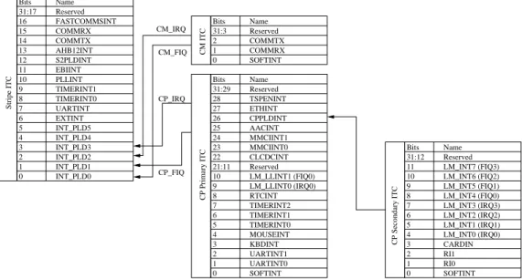
The CP 922T-XA10 embed four different interruption controllers (ITC). The stripe’s interruption controller is always connected directly to the CPU exception wires. The three extra ITC are thus connected to the first one. In fact they are connected to the stripe’s ITC by four wires reserved to FPGA exception sources (two wires for each ITC, an IRQ wire and a FIQ wire). Then the first ITC’s priority are configured so that it relays IRQ and FIQ.
The three extra ITC are CM interruption controller and two CP interruption controllers (primary and secondary). CM ITC and primary CP ITC are implemented in the FPGA. The third one is implemented in a PLD on the compact platform and is connected to the primary CP ITC by an interruption wire.
More generally, the CM interruption controller is connected to CM peripherals, and the CP interrupt controllers are connected to the CP peripherals. Figure7presents the hierarchical relations between inter-ruption controllers.
1.2.3 Memory map
As for CM 922T-XA10, all peripherals of the CP 922T-XA10 are mapped in memory. Moreover, they are mapped in the address space still available in the CM 922T-XA10 memory map.
0 1 2 3 4 5 6 8 21:11 7 9 10 LM_LLINT1 (FIQ0) LM_LLINT0 (IRQ0) RTCINT TIMERINT2 TIMERINT1 TIMERINT0 MOUSEINT KBDINT UARTINT1 UARTINT0 SOFTINT Name Bits Reserved 31:29 Reserved 22 24 25 26 27 28 CLCDCINT MMCIINT0 AACINT CPPLDINT ETHINT TSPENINT 23 MMCIINT1 CP Primary ITC 0 1 2 3 4 5 6 8 11 7 9 10 PLLINT TIMERINT0 UARTINT EXTINT INT_PLD5 INT_PLD4 INT_PLD3 INT_PLD2 INT_PLD1 INT_PLD0 EBIINT 14 15 16 S2PLDINT AHB12INT COMMRX FASTCOMMSINT 13 COMMTX TIMERINT1 12 31:17 Reserved Name Bits Stripe ITC 0 1 2 COMMRX COMMTX Reserved 31:3 Bits Name CM ITC SOFTINT CM_FIQ CM_IRQ CP_FIQ CP_IRQ 0 1 2 3 4 5 6 8 11 7 9 10 31:12 Reserved LM_INT6 (FIQ2) LM_INT5 (FIQ1) LM_INT4 (FIQ0) LM_INT3 (IRQ3) LM_INT2 (IRQ2) LM_INT1 (IRQ1) LM_INT0 (IRQ0) CARDIN RI1 RI0 SOFTINT LM_INT7 (FIQ3) Bits Name CP Secondary ITC
Figure 7: CP interruption management. Stripe ITC is directly connected on CPU INT_nFIQ and INT_nIRQ.
The resulting memory map is shown by figure8.
0x10000000 0x08000000 SDRAM0 SDRAM1 SRAM0 SRAM1 DPSRAM0 DPSRAM1 Stripe Register Undefined EBI1 EBI2 Undefined 0x08100000 0x08110000 0x0B000000 0x0F000000 0x04000000 0x08020000 0x0F800000 CM Registers Reserved SSRAM POR Static Static System Bus 0x10000100 0x10800000 0x11000000 0xFFFFFFFF Default Slave Stripe Peripherals 0x20000000 0x28000000 0xC0000000 0xC1000000 0xC8000000
Figure 8: CP 922T-XA10 memory map
1.3
ARM 922T architecture
We will give here more details about the ARM 922T architecture, that is to say about its core, its caches and its MMU, particularly their characteristics and their organisation.
1.3.1 Global architecture
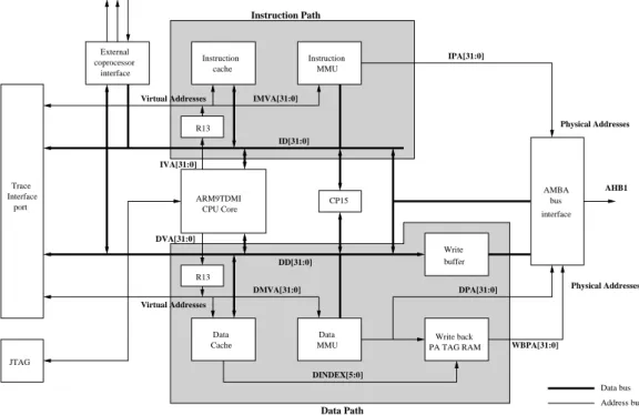
First, we give here an overall view of this processor. As one can see form figure9, ARM 922T has seperate instruction and data paths. These paths have their own cache and MMU/TLB. A common AHB interface connects the two buses to the general purpose AHB bus. We must underline the presence of the CP15, which is a configuration coprocessor, it allows us to set MMU, caches, . . . configurations.
Physical Addresses Physical Addresses Virtual Addresses Virtual Addresses Instruction Path Data Path ARM9TDMI CPU Core Cache Data MMU
Data Write back PA TAG RAM buffer Write Instruction cache Instruction MMU coprocessor interface External interface AMBA bus Address bus Data bus R13 AHB1 ID[31:0] IMVA[31:0] WBPA[31:0] DINDEX[5:0] CP15 R13 IPA[31:0] Interface Trace port JTAG DVA[31:0] IVA[31:0] DD[31:0] DPA[31:0] DMVA[31:0]
Figure 9: ARM 922T architecture
1.3.2 ARM9TDMI core
The CPU core of the ARM 922T is an ARM9TDMI. This core fully implements the 32 bit ARM v4 ISA (Instruction Set Architecture). It also support the Thumb instructions which are 16 bit instructions. As most ARM CPUs it has no floating point unit, it supports only integer operations. This processor has multiple operating modes, user, system, supervisor, IRQ, FIQ, undefined and abort modes. Among these modes only user mode is unprivileged. Finally, as far as registers are concerned, it has 16 general purpose registers (among which are SP stack pointer, LR link return and PC program counter). These registers are banked, which means that some registers are not common between certain operating mode.
1.3.3 Caches
The ARM 922T has seperated instruction and data cache. Their size is 8 ko, and the write buffer has a size of 16 words.
These caches are virtually addressed. On top of that, the data cache can only be used when MMU is activated. In fact the control bits, which indicates if the cache and the write buffer must be used for a data region are part of the page table entries. The caches are made of 265 lines of 8 words. They are organized in a 4-way associative way.
1.3.4 MMU/TLB
The MMU integrated in the ARM 922T is an ARMv4 MMU. We will give here more details about the behavior of this MMU.
First of all, we must underline the fact that instruction and data have their own TLB (Translation Look-aside Buffer), translation cache. These TLBs have a 64 entry width.
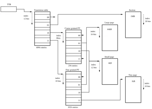
In the ARMv4 MMU, memory can be accessed through four different page or section size : 1ko (tiny page), 4ko (small page), 64ko (large page), 1 Mo (section). These pages and sections are accessible through one or two stage table walking depending on page-mapped or section-mapped access. Before going any further it is important to underline the fact that all page walkings are made in hardware. Thus the translation is all made in hardware, and MMU only raises prefetch abort exception when no translation are possible or access to the memory region is not granted .
Translation base
The translation starts when TLB contains no translation for a virtual memory address. Then the translation table base address gives the location in physical memory of the first stage table. This register is in the configuration coprocessor CP15.
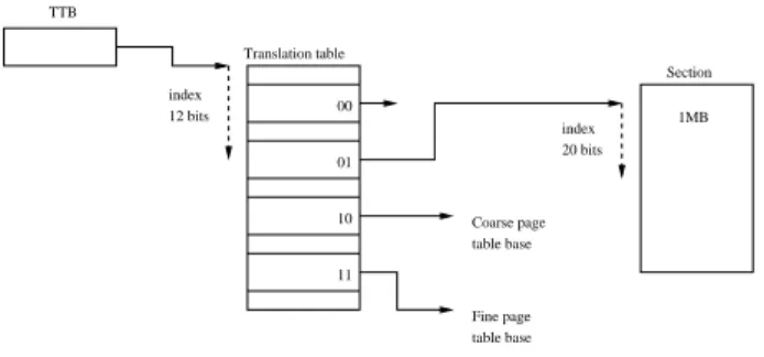
Level 1 : Translation Table
The first stage table is also called translation table. It is 4096 entries long, which means that its size is 16 ko. Each entry in this table represents 1Mo of virtual memory. As you can realize from figure10, there are four different type of entries in this table.
1MB 00 01 10 11 index 12 bits table base Fine page Coarse page table base index 20 bits Section Translation table TTB
Figure 10: ARMv4 MMU level 1
The first type is the section descriptor. As we said before, memory is accessible through section. Obviously these sections have a size of 1 Mo. All informations about domain protection, cache and write buffer are present in this first level entry.
The two following types of entries are page entries. There are two different types of page table : coarse grained and fine grained. The first level entry in these case only gives the base address of the corresponding second level page.
The fourth type is undefined and generates an error.
Level 2 : Page tables
At this leve, we have two different type of page table, the coarse grained and the fine grained page table. As their name indicates, the first type describes its 1Mo region with big pages and the second one with smaller pages.
The page size can have three different sizes : 1ko (tiny page), 4ko (small page), 64ko (large page). Coarse grained page table entries can only describe small or large page. However, Fine grained page table entries can descibe tiny, small or large page entries. This difference is due to the following fact. Coarse grained page table divides its 1Mo in 4ko blocks, so it has only 256 entries. When a large page descriptor is set, it is repeated on the 24 contiguous blocks descriptions. For fine grained page table the situation is the same, but it divides its 1Mo in 1ko blocks (it is 1024 entries). If a small or a large page description is set the description is repeated on all the blocks descriptor the page contains. The figure11summarize this second level description relations.
To conclude, figure12give an global view of the two level page table organisation.
2
Booting Linux on the platform
At this point we have a better knowledge of the hardware we are working on. We will now review the few steps necessary to make an operating system (OS) boot on such platforms.
64 kB 4kB 1kB 00 01 10 11 00 01 10 11 index 10 bits Large page index 16 bits Small page index 12 bits Tiny page index 10 bits Coarse grained PT Fine grained PT index 8 bits
Figure 11: ARMv4 MMU level 2
Coarse grained PT 00 01 10 11 01 Fine grained PT 256 entries 1024 entries index 12 bits index 8bits index 10 bits index 12 bits index 16 bits index 20 bits index 10 bits TTB Large page Section 4kB 1kB Tiny page Small page 01 10 11 4096 entrées Translation table 00 11 10 00 64kB 1MB
Figure 12: Global MMU access diagramm
It is important to underline that the compact platform is well supported under ARM Linux kernel. We will then focus on the CP 922T-XA10 in this section, because the CM 922T-XA10 is not supported.
In the next subsections we will go over the next points : loading the kernel (boot loader), and the two kernel Linux and uClinux.
2.1
Boot loader
First of all, to make an OS, like Linux, boot, we must copy the kernel in memory and put the machine in a state that allow it to work properly in the first critical steps. The little piece of software that is in charge on this job is the boot loader.
Classical boot loaders likeliloandgrubare designed for more complex machines. For ARM based platform, few boot loaders are available, but our choice was to take a boot loader nameddas U-Boot, for universal boot. U-Boot supports the ARM Integrator/CP.
The goal of the boot loader is to initialize the platform, that is to say to put it in a known state. During the first steps of kernel booting, before Linux fully initializes the hardware, Linux uses few hardware peripherals (serial port, memory, . . . ) that have to be in the right state when we jump to the kernel. Once the platform is initialized, the boot loader copies the kernel in main memory and optionally an initrd. An initrd is a file system usually used by the kernel at boot time, but it can also be used as final root file system in embedded systems. Then the boot loader must give some information to the kernel before giving control to it. The first two information are to put the value 0 in register r0 and put the machine ID in register r1. The machine ID is a unique number which is used to identify the type of platform. Thus during the first steps of booting, Linux can check if it was configured for the platform it is running on. These machine ID are listed in a file in the kernel source tree : arch/arm/tools/mach-type. The last information is the kernel parameters structure named ATAG. The boot loader places this structure in the main memory. For example this structure gives information on the main memory (size and base address). In order that the kernel can find this structure, it is placed at a fixed address set beforehand.
We must add a few details about the state of the machine when the kernel gets the control. First, a standard output console must be initialized, to print messages in the early stages of kernel. The boot loader must take care to inhibit the MMU and caches too, if it is using it.
2.2
Compiling and using the Linux kernel
Linux was initially developed for big systems like personal computers. For few years now it has been ported on smaller targets and became a complete embedded operating system. Then booting Linux on the CM 922T-XA10 is not meaningless. Linux supports a large range of architecture, ranging from m68k to IA64 (for example). Thanks to the project ARM Linux it was also ported to ARM architecture. This port integrates today many platform support in which we can find the Integrator/CP platform.
The port is designed to work with the CP regardless of which core module is mounted on. It implements only the driver of all CP peripheral in a more or less stable way. We only need here to choose the driver we want to build in our kernel before compiling it.
2.2.1 Linux and application compilation
Once the configuration of the kernel is made, we have to compile it. All steps of the kernel building are made on a computer whose architecture is different from the platform, we work on a x86 host under GNU/Linux. The standard GCC (GNU Collection of compiler) proposed on this host does not allow to produce ARM binary, but x86 binary. We must then use a cross compiler. It is possible by recompiling the GCC tool chain with the right host/target combination.
It is possible to build two different tool chains. The first can be called core cross compiler or bootstrap compiler. This tool chain is obtained by only compiling binutils (as,ld, . . . )and the GCC. This tool chain can be used to compile the Linux kernel or all home brew application which will run directly on the platform. AppendixAshows our core tool chain compilation script. The second tool chain is more complex. It is obtained by compiling a bootstrap compiler, a libc (glibc most of the time) and recompiling the GCC with full support (shared libraries, . . . ). This tool chain may be used to compile applications which will run on the Linux kernel.
There exists some tools to help compiling these tool chains. For example, crosstool [6] is a script building a full compilation tool chain for Linux on many architecture among them ARM.
2.2.2 Linux root file system
The last thing to fix for booting a GNU/Linux operating system is the root file system.
Indeed, after booting, the kernel mounts the root file system and then executes theinitprogram (by default /sbin/init). Therefore this file system must contain the root of the file system tree, and ARM Linux executable files. The simplest solution is to get sources of each program you want to integrate in your
embedded GNU/Linux OS, and then cross compile them with the compiler built in the previous step. This solution is simple but very time consuming.
To solve this problem, thebusyboxsoftware was proposed.busyboxregroups all basic applications that are useful on a minimal GNU/Linux OS in a single executable file. After a configuration phase, during which you can choose the applications you need, you only have to cross compile it.
2.2.3 Firmware loading
The combination of the boot loader, the kernel image and the root file system image can be also called the firmware. To be used on the platform you now need to load it either in main memory or in ROM.
In the first solution, you need to load it every time you boot the platform. This configuration can be useful if you are in development process. For example, on the Integrator/CP the boot loader can be loaded by serial port transfer, the kernel image and root file system can be transferred using thebootpprotocol. The root file system is an initrd in this case. Another solution is that the root file system is mounted via NFS protocol. In this solution the platform must be connected with the development host by a serial or Ethernet cable.
If the development phase is over, and you want a more autonomous solution, i.e. without connections with a host, you may need to load the firmware on the flash memory. In this case all three images can be placed in the flash memory. In this configuration the boot loader, the kernel and the root file system images are copied from the flash into the main memory. This is the initrd solution. An alternative solution would be to use a file system like JFFS/JFFS2 (Journaling Flash File System). In that case the file system is read-only and used on the flash memory.
These solutions are only examples. It is obvious that other combinations are possible.
2.3
Compiling and using the uClinux kernel
On top of using the Linux kernel, we focus on another kernel, which is only a modification of the vanilla Linux kernel. This modification is called uClinux. This name comes from the first target of the port, micro controllers. In fact uC stands for micro-controller because “u” is the Greek letter µ (micro) and “C” for controller. On micro controller based platforms, the memory management is most of the time much simplified, because no MMU (Memory Management Unit) is integrated. The memory address space is called a “flat” memory model. There is only one address space shared by all applications and the operating system. This is the direct consequence of the lack of MMU, as it is in charge of translating virtual memory addresses into physical addresses.
uClinux was a posteriori ported to architectures where an MMU is present, but it does not use it, or to architectures where the memory management hardware is just designed for memory protection, like MPU (Memory Protection Unit) on some ARM CPUs (ARM 946ES for example).
This modification offers interesting perspectives because hardware in embedded systems is often lack-ing memory management. Thus uClinux is a good replacement solution for Linux there.
Thanks to the work of Hyok S. Cho, uClinux was ported to the ARM9. The integrator/CP is then supported by uClinux, as most of the ARM Linux supported platforms.
2.3.1 uClinux and applications compilation
The compilation of an uClinux kernel is quite the same procedure as the one to compile a Linux kernel. The compiler used is a core cross compiler, the same as the one compiled for Linux.
What makes the difference is when you want to compile applications for GNU/uClinux. The trou-ble here is that you must change your cross compile tool chain, because it produces binary in an ELF format. This format is based on the fact that each application has its own address space starting from
0x00000000, and this is exactly the role of the MMU. In contrast the binary format used by uClinux is called Flat format, bFLT. This executable binary format has the same structure than an ELF binary file, but a relocation table is added at the end of the file. This table contents is a list of positions, more precisely
offsets from the beginning of the text segment, where a relative address was placed during the last com-pilation phase. At loading time, the only computation needed is to add the base address to the entire list entries in the relocation table.
The compilation tool chain used is close to the one used for ELF application compilation. We only have to add a tool whose aim is to process all addresses and create the relocation table at linking time. This tool is calledelf2flt[8].
Practically, we do not use the standard glibc, because its size is far too important. Instead we use an implementation of the libc optimized for small footprint, uClibc [17].
2.3.2 uClinux root file system
As for Linux, uClinux needs a root file system. Unfortunately, we cannot use the same file system because the application building process do not use the same memory model. It is necessary to rebuild all these application with the special cross compilation tool chain. Except this point the procedure is the same as for GNU/Linux OS.
3
Porting the Linux kernel on the CM922T-XA10 platform
In contrast to the integrator/CP, the integrator/CM 922T-XA10 is not supported by the Linux kernel. We were particularly interested in using the CM 922T-XA10 in standalone mode for the remaining of our work, hence we ported Linux to this platform.
As we explained in the section dedicated to the hardware description, the architecture of the CM 922T-XA10 is centered on the Altera Excalibur EP922T-XA10. We showed in the previous section that the implemen-tation of Linux on the integrator/CP does not take advantage of the CM 922T-XA10 peculiarities. This implementation cannot run on the CM 922T-XA10 in standalone mode. The following subsections will give a description on our work to get Linux boot on our CM.
3.1
Porting the boot loader
The first step of this work is obviously to get a working boot loader. The Integrator/CM 922T-XA10 was not in the list of supported platform of U-Boot, so we had to port the boot loader prior to any other work.
Porting the boot loader is a good first experience in the process of porting full operating systems, because it can be considered as a very simplified OS. Indeed it only needs a serial port for console and some peripheral initialization like timer.
First of all, as no support for this platform already exists, we must create our platform in U-Boot. By creating a platform we mean add thecm922txa10choice in the configuration tool. This configura-tion phase is made by callingmakefollowed byplatformname_config. The first action is then to modify the U-BootMakefile. In this file we can find a huge list of targets, among them we find the
integratorcpone :
integratorcp_config : unconfig
@./mkconfig $(@:_config=) arm arm926ejs integratorcp
This target calls the configuration script with the following arguments. First field is grab from the target name, hereintegratorcp. This field will give the name of the configuration file include-/configs/integratorcp.h.The second field is the arch, in that case arm, used for simlink the
include/asmon include/asm-arm. Third field is CPU, arm926ejs. A simlink is build be-tweeninclude/asm/arch-arm926ejsandinclude/asm/arch. And finally the board name,
integratorcp. Extra fields can be present like vendor and SOC (System-On-Chip). As you can realize from this description, the CP implementation is based on the ARM 926EJS which is an ARM9 like ARM 922T which implements ARM v5 instruction set, whereas 922T implements ARM v4t instruction set.
In thecpufolder, we can find two extra ARM9 CPU, ARM 920T and ARM 925T. It is safer to use the support of an ARM 920T as implementation base since it is an ARM v4t. In fact ARM 920T and 922T have the same core processor (ARM9TDMI), the only difference between the two of them are the cache
sizes which are 16kB for instruction and 16kB for data on the 920T and I 8kB/ D 8kB for the 922T. This difference is meaningless since U-Boot do not use any cache.
The implementation of the ARM 920T is a SOC based implementation (in U-Boot). We had to build a SOC implementation for the EPXA10, with a lack of imagination we called itepxa10. For example this port integrates the serial port, timer, and other peripherals of the stripe drivers. This SOC implementation has a huge advantage, re-usability in other EPXA10 based platforms ports. The vendor field will stay empty in our case, so the config line becomes :
cm922xa10_config : unconfig
@./mkconfig $(@:_config=) arm arm920t cm922xa10 NULL epxa10
Now we have our configuration target ready. Next step is to provide the SOC implementation in the
cpu/arm920tfolder. All we need is to create a folder which will contain all specific implementation for our new SOC (epxa10). This folder must have for name, the name given in the config line. We put here all minimal drivers needed by U-Boot that are directly available on the EPXA10. Thus we have the serial driver, the timer driver and some PLL information fetch drivers. The driver for the serial port is not used in any other platform supported by U-Boot, it is logical to keep it in this SOC implementation. The source code of the driver is placed in the fileserial.c. interrupts.cdoes not include some interruption handler sources, but a minimal timer driver for delay loop purposes. Thespeed.cfile contains few functions used by the two other files. These functions fetch the clock speed, in order to calibrate the serial port or the timer. To conclude, theMakefileof this folder must be filled with the names of the three files to compile :
OBJS = interrupts.o serial.o speed.o
Once the EPXA10 support is completed, we have to build our board support. This support must be placed in theboardfolder. In this folder, we have to create a sub-folder whose name is the name of the board given in theMakefileconfig line. Then we create theboard/cm922xa10folder. Here we put all functions specific to the platform, for example the drivers of peripherals implemented in the FPGA. Most of the functions required by U-Boot are empty functions. Indeed, in filelib_arm/board.cwe can find a structure namedinit_sequencecontaining function pointers of all initialization functions. Among these functions, some must be implemented in the board support. For example, theboard_init
and thedram_init, which are defined inboard/cm922xa10/cm922xa10.c. It’s important to note that the information put in the structuregd(its definition is in fileinclude/asm/global_data.h), will be used in the ATAG structure to inform the kernel on the amount of memory and the machine ID for example. Another file is present in this folder, but it is not really important,memsetup.S. All actions usually placed in this assembler function are made by the ARM bootmonitor. The functionmemsetupis then empty.
The last things to add in the source tree are the header files. One header file is mandatory, it is the configuration header file. Its name is the name of the board,cm922xa10.hin our case, and it is placed in a special folder,include/configs. This file contains configurations for the drivers we decide to compile in our U-Boot, like serial driver. It allows us to make a selection of the U-Boot command we would like to integrate in it,bootpcommands for example. And finally it sets some default configurations, which can also be modified at run time, likeBOOTARGS. Other header files are placed in theinclude
folder, and their names areepxa10.handcm922xa10.h, each of them defining a specific part of the platform.
3.2
Porting Linux
Once the boot loader is ready to load the kernel in main memory, the last step is to adapt the Linux kernel to work on our hardware. As we mentioned before, the CP is already supported by the kernel, but this implementation is not designed to use EPXA10 special hardware. The idea here is to start from scratch or to find a platform with a similar architecture in the existing kernel implementations.
After few research it appears that the support of a platform named EPXA10db (development board) was implemented in the ARM Linux kernel. The most interesting thing is that this implementation offers a good support for most of the EPXA10 stripe peripherals.
We will now give a few details on how this support was modified. To do so we follow the order of kernel boot sequence.
3.2.1 Adding a new platform
Since the EPXA10db and the CM922T-XA10 are two quite different integrations of the Altera Excalibur, their support have two much difference to be merged. The differences in the memory mapping are what prevents us to merge them. The decision was taken to create a new machine.
To add a new machine (or platform) in the ARM Linux kernel, we first need to register it on the ARM Linux Project website [4]. This registry is mandatory, because it adds the machine in the database contained in thearch/arm/tools/mach-typesfile. The information of this file are the machineID, and some variable names used at compile time or at running time to identify the machine. One important thing is that this file is automatically generated with the registry information provided by the maintainers of the machine. During the development phase we decided to create the entry in themach-typesfile by hand, without registering the platform. To do so, we choose a sufficiently high machineID (999) to avoid overlapping if we decide to change kernel version while developing. The line added at the end of the
mach-typesfile is then :
# machine_is_xxx CONFIG_xxxx MACH_TYPE_xxx number
# [...]
epxa ARCH_CAMELOT CAMELOT 62
[...]
cm922txa10 MACH_CM922TXA10 CM922TXA10 999
The following step is to create the folders containing the support of our new support. As we got a good base for future developments which is EPXA10db, we can create these folders by copying the folders of the EPXA10db. Then inarch/arm/we copymach-epxa10dband call the new folder mach--cm922txa10.
The second folder that have to be created is in the include sub-tree, and will regroup the header file specific to our machine. include/asm-arm/arch-epxa10dbis copied and named include-/asm-arm/arch-cm922txa10.
At this point, we have all our new machine support skeletons. We now have to make it accessible during the configuration phase of the kernel, for example withmake menuconfig. The files used by the con-figuration tools are namedKconfig. First of all, we have to modify the top levelarch/arm/Kconfig. In this file, we add the new platform in theSystem Type / ARM system typechoice menu. This addition is made by an extra config entry. Here is what we add (ARCH_CAMELOTwas already present since it is epxa10db machine) :
[...]
config ARCH_CAMELOT bool "Epxa10db" help
This enables support for Altera’s Excalibur XA10 development board. If you would like to build your kernel to run on one of these boards then you must say ’Y’ here. Otherwise say ’N’
config MACH_CM922TXA10
bool "CM922T-XA10 Standalone" help
This enables support for ARM Integrator CM922T-XA10 when used in standalone mode. This platform is based on an Altera Excalibur EPXA10 If you would like to build your kernel to run on one of these boards then you must say ’Y’ here. Otherwise say ’N’
The field placed afterconfigmust be the same than the second field in themach-typesfile. The text displayed in the choice menu will be"CM922T-XA10 Standalone"
On top of this minimal configuration, we should want extra specific configurations for our machine. In that case, we create aKconfigfile in ourmach-cm922txa10folder. In our case, this field will remain empty, because we have no special configuration to add. But in case of future development, we place the following content in filearch/arm/mach-cm922txa10/Kconfig:
if MACH_CM922TXA10
# here comes machine special configurations endif
To use this file, we only need to include it in thearch/arm/Kconfig, by adding the line :
[...]
source "arch/arm/mach-epxa10db/Kconfig" source "arch/arm/mach-cm922txa10/Kconfig" [...]
Final configuration setting to be made is to give a default configuration to kernel. The default con-figuration is contained in a file namedcm922txa10_defconfig. This config file can be generated with a make menuconfig and then copyed from .config to arch/arm/configs/cm922t-xa10_defconfig
A little modification of otherKconfigfiles is needed, thearch/arm/mm/Kconfigwhich is in charge of selecting the CPU the kernel is compiled for. We just have to tell him that the ARM922T is part of our machine :
[...] # ARM922T
config CPU_ARM922T
bool "Support ARM922T processor" if ARCH_INTEGRATOR
depends on ARCH_CAMELOT || ARCH_LH7A40X || ARCH_INTEGRATOR || MACH_CM922TXA10 default y if ARCH_CAMELOT || ARCH_LH7A40X || MACH_CM922TXA10
select CPU_32v4 select CPU_ABRT_EV4T select CPU_CACHE_V4WT select CPU_CACHE_VIVT select CPU_COPY_V4WB select CPU_TLB_V4WBI help
The ARM922T is a version of the ARM920T, but with smaller instruction and data caches. It is used in Altera’s Excalibur XA device family.
Say Y if you want support for the ARM922T processor. Otherwise, say N.
[...]
Once the configuration facilities are in place, we now tell the kernel that it will have to compile some stuff in themach-cm922txa10folder. This is done by modify thearch/arm/Makefile, and adding the following line :
[...]
machine-$(CONFIG_ARCH_CAMELOT) := epxa10db
machine-$(CONFIG_MACH_CM922TXA10) := cm922txa10
As you could have notice from themach-typesfile, the name of the variable is not MACH_CM922T-XA10, butCONFIG_is appended by the configuration tool, and this variable contains either a ’n’ or an ’y’ (for no or yes boolean value). If it is selected (yes value), the name of the folder of our machine is appended to the machine-y variable, which contains the folders to be visited during compilation (
mach-is automatically appended). makewill enter in our folder, but we must tell him what it must do, then we create thearch/arm/mach-cm922txa10/Makefilewith the content :
#
# Makefile for the linux kernel. #
# Object file lists.
obj-y := arch.o irq.o mm.o time.o
obj-m :=
obj-n :=
obj- :=
ThisMakefileis quite static since we have no configuration available at this time. Object files listed here are inherited from the EPXA10db machine support. In the same folder we have to put an extra
Makefile, theMakefile.bootwhich only contains the physical address of the text segment (this gives the value ofZRELADDR, which is the physical address ofTEXTADDR) :
zreladdr-y := 0x00008000
We now have the base configuration and compilation infrastructure of the kernel for our new machine. We have now to work on the main part of the job, implement the support of the platform.
The implementation of our support begins with the creation of the structure that describes the ma-chine. This structure will be placed in the filearch.c(this name can be freely chosen) in the arch-/arm/mach-cm922txa10. Macro helper are defined to simplify the work. The definition looks like this :
extern void cm922txa10_map_io(void); extern void cm922txa10_init_irq(void); extern struct sys_timer cm922txa10_timer;
MACHINE_START(CM922TXA10, "ARM Integrator CM922T-XA10") /* Maintainer: Nicolas Fournel */
.phys_ram = 0x00000000, .phys_io = 0x0x0B000000, .io_pg_offst = ((0x0B000000) >> 18) & 0xfffc, .boot_params = 0x00000100, .map_io = cm922txa10_map_io, .init_irq = cm922txa10_init_irq, .timer = &cm922txa10_timer, MACHINE_END
Arguments of the structure listed here are, physical address of main memory (.phys_ram), physi-cal address of I/O bank (.phys_io), I/O page offset, which allows to give virtual memory ( .io_pg-_offst), boot parameters address (.boot_params), the I/O memory mapping function (.map_io), the IRQ initialization function (.init_irq) and the timer structure (.timer). We can find additional fields, but they are not used here.
3.2.2 Deflation phase
The first step when the kernel gets the control is a deflation phase. In this phase, a piece of code extracts the kernel from the binary file copied in main memory.
The source code of this part sits in the folderarch/arm/boot/compressed/.
The entry point of the kernel is located inhead.S. Here are made pre-extraction configurations. For the sake of performance, instruction and data caches are enabled. But on ARM v4 CPU, the only mean to activate data cache is to use MMU. Indeed, the control bits which tells if a memory address is cache-able and buffer-able or not are placed in the page table entries. The use of the MMU is then mandatory. The memory mapping used in this stage is the simplest one, which is to say identity mapping : physical adresses and virtual addresses are equal.
Once the configuration is made, it launches a C function calleddecompress_kernel()in mis-c.c. In this function the well-known printingsUncompressing kernel ... done. are made on the selected console device, in our case this is the serial port. No initialization of the serial port is made at this early point, so this initialization is a task of the boot loader. We implemented it in U-Boot.
Finally the caches are disabled and the control is passed to the next stage, end ofhead.S.
In these parts, only two things should be implemented in regard of the new platform. The first is some debug macros in thedebug_macro.Sfile ininclude/asm-arm/arch-cm922txa10. These macros are used to print messages for debug purposes. Second thing to implement is a function imple-mented ininclude/asm-arm/arch-cm922txa10/uncompress.h. This function,putstr()
is called to print messages on the console, it is machine dependent.
Except these two functions, nothing else should have to be modified, but in our case the situation is a bit different. The main trouble when activating the MMU is to take care not to map the register bank as cache-able/buffer-able memory region. We should only set these characteristics on the RAM region. By default, the ARM-Linux kernel uses the write buffer on a region of0x10000000bytes starting at the start address of main memory (in fact first address of the kernel file aligned on the 1MB page below). Unfortunately the stripe control register bank is mapped at0x0B000000by default on the CM922T-XA10, although it is mapped at0xFFFC0000on the EPXA10db. As the UART transmit register is in the register bank of the stripe, it is buffered and only written once in the register, producing a message with only half of the characters.
The only way to solve this trouble is to reduce the main memory region. This modification has no effect on the following stages of the kernel boot, because the MMU and caches are stopped just before jumping to the newly uncompressed kernel.
3.2.3 Linux kernel boot
In this second stage of boot, the kernel will really initialize the hardware and the execution environment. Before doing anything, the kernel takes care to check if it is running on the CPU it was compiled for. This verification has for main interest to initialize the basic functions responsible of initializing the caches and the MMU. To do so, it embeds two structures called.proc.infoand.arch.info. The structure
.arch.infois in fact the structure defined in thearch.cfile. Structure.proc.infois very similar structure, with information and specific functions related to the CPU. The kernel gets the processor ID (cpuid) from the configuration coprocessor and compares it to the data contained in the.proc.info
structure. It uses the machine ID given to him by the boot loader and checks in the.arch.infoif it is the same ID. All these steps works fine by default, once we take care to create a machine with the right information. Processor ARM 922T was already supported, andcm922txa10is the name of our new machine.
The following step is the MMU configuration. This configuration is very critical since it is the switching from physical to virtual address modes. What makes it more difficult than in the first stage is that, this time the mapping will not be the identity one. Linux has a specific usage of the virtual address space.
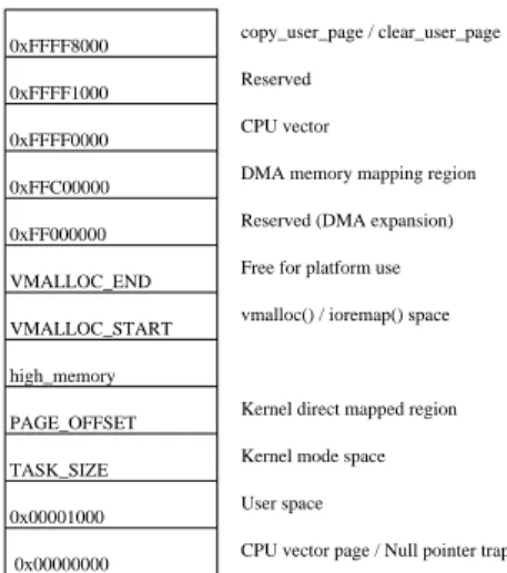
Before giving the details of this mapping, we must underline the fact that this mapping is made in two distinct phases. In the first one, the kernel initializes the page table memory region and direct map 4MB where the kernel is laying. The second phase finishes building a minimal page table mapping. In Linux, the address space available for applications starts from address0x00000000but does not contains the whole 4GB. Figure13gives a global view of the usage of this virtual memory mapping.
As shown on the figure, the last 1GB are reserved for kernel use. At the beginning of this space, physical memory is directly mapped (kernel direct mapped region), which means that we only have to add an offset to the physical address to get the virtual address. The offset here is0xC0000000named
0x00000000 TASK_SIZE PAGE_OFFSET 0x00001000 high_memory VMALLOC_START VMALLOC_END 0xFF000000 0xFFC00000 0xFFFF0000 0xFFFF1000 0xFFFF8000 User space Kernel mode space Kernel direct mapped region Free for platform use
vmalloc() / ioremap() space
CPU vector page / Null pointer trap copy_user_page / clear_user_page
Reserved
CPU vector
DMA memory mapping region
Reserved (DMA expansion)
Figure 13: Linux memory layout
PAGE_OFFSET. The figure also shows that a special region is reserved for platform use (Free for platform use). In this region, all I/O control registers must be mapped to keep them accessible after virtual memory activation. To know what correspondences it must implements, the kernel needs a structure containing the address translations. This structure is named the I/O memory map presented before and is specific to the platform you are porting. The structure and the function related to the I/O memory map are placed in themm.cfile in ourmach-cm922txa10folder. In our case the memory map is quite simple. Since all control registers of stripe’s peripherals are regrouped in a bank mapped at0x0B000000, we only need to add an entry to give it a mapping as in the following structure.
static struct map_desc cm922txa10_io_desc[] __initdata = {
{ IO_ADDRESS(0x0B000000), 0x0B000000, SZ_16K, MT_DEVICE },
{ IO_ADDRESS(0x10000000), 0x10000000, SZ_8M, MT_DEVICE }
};
This I/O memory description also contains a mapping for the CM control register bank mapped in physical memory at0x10000000.
IO_ADDRESSis a macro defined to give an automatic translation from physical to virtual address for peripherals in device drivers. Default one is the following :
#define IO_ADDRESS(x) (((x) >> 4) + 0xF0000000) .
Following initializations are timer and IRQ ones. As we saw in the machine structure, there are struc-ture/function for this two initializations. As far as IRQ are concerned, we give to the kernel a func-tion that is responsible of the initializafunc-tion of the hardware interrupt controller. This funcfunc-tion is named
cm922txa10_init_irq()and is defined in theirq.cfile inmach-cm922txa10folder. In this function a structurestruct irqchipis registered to give to the kernel the functions to use for masking and unmasking an IRQ. On top of that, we must help the kernel to find which IRQ is raised. This function is made in an assembler macro placed in fileentry-macro.Sinarch-cm922txa10. This macro only reads an ITC register giving the highest priority of IRQ raised, but priorities are initialized to the IRQ num-ber. The return value is then the IRQ numnum-ber. IRQ numbers allocations are given by the fileirqs.hin
include/asm-arm/arch-cm922txa10. For the timer, the structure registered in the machine struc-ture contains the timer intialization function pointer. In this function, all necessary registers are set to the right value, and the timer IRQ is activated. Timer initialization is made thanks to a structure. This structure has an init function pointer field. This one is implemented in thetime.cfile inmach-cm922txa10. It sets timer control registers to desired values and starts the timer. Finally it activates the timer IRQ, for preemption purpose.
At this step, we have the following files inmach-cm922txa10:
arch/arm/mach-cm922txa10/irq.c arch/arm/mach-cm922txa10/Kconfig arch/arm/mach-cm922txa10/Makefile arch/arm/mach-cm922txa10/Makefile.boot arch/arm/mach-cm922txa10/mm.c arch/arm/mach-cm922txa10/time.c
In thearch-cm922txa10folder we talked about these files :
include/asm-arm/arch-cm922txa10/debug-macro.S include/asm-arm/arch-cm922txa10/entry-macro.S include/asm-arm/arch-cm922txa10/irqs.h
include/asm-arm/arch-cm922txa10/uncompress.h
We now need to add few files in this last folder. First we put hardware definitions in the files :
include/asm-arm/arch-cm922txa10/cm.h include/asm-arm/arch-cm922txa10/excalibur.h include/asm-arm/arch-cm922txa10/hardware.h include/asm-arm/arch-cm922txa10/int_ctrl00.h include/asm-arm/arch-cm922txa10/platform.h include/asm-arm/arch-cm922txa10/timer00.h include/asm-arm/arch-cm922txa10/uart00.h
Finally, we have to place mandatory files. These files are needed for kernel compilation, but do not contain machine specific information except in very special cases :
include/asm-arm/arch-cm922txa10/dma.h include/asm-arm/arch-cm922txa10/io.h include/asm-arm/arch-cm922txa10/memory.h include/asm-arm/arch-cm922txa10/param.h include/asm-arm/arch-cm922txa10/system.h include/asm-arm/arch-cm922txa10/timex.h include/asm-arm/arch-cm922txa10/vmalloc.h
The new platform/machine is now ready to be configured and compiled. Our kernel would boot, but we could not do anything with it because we only give the minimal support here. No drivers are supported, then no messages will be output for exemple. So the last job is to work on device drivers. We already put minimal driver support in the kernel, timer and interrupt controller. Remaining drivers are serial port driver for console input/output for example. Fortunately these peripherals are stripe’s one. The EPXA10db implements all these drivers. To allow them to compile with our new machine, we need to modify con-figuration files, because we cannot select them, they are hidden. We will take the example of serial port, namedUART00in the Altera port of EPXA10db. In the filedrivers/serial/Kconfigwe modify
UART00entry as follows :
config SERIAL_UART00
bool "Excalibur serial port (uart00) support" depends on ARM && (ARCH_CAMELOT || MACH_CM922TXA10) select SERIAL_CORE
help
Say Y here if you want to use the hard logic uart on Excalibur. This driver also supports soft logic implementations of this uart core.
With this modification, the driver is now selectable during configuration phase, but we have to modify the driver itself to get it to compile. These modifications are based on the low level hardware defini-tion. Once these modifications accomplished the driver compiles and works. Another good exemple of driver “port” is the Flash. In fact on the CM922T-XA10, the flash memory is partitionned thanks to ARM Firmware Suite (AFS). To use the MTD (Memory Technology Device) on our Flash, we must make the
AFS work on our flash. This is done by putting initialization actions. We place in thearch.cfile some functions which are responsible of placing the flash in a state where it can be read and written. Point-ers ofthese functions are placed in structures, where we put some informations about addresses and type (armflash)
[...] /*
* Flash handling. */
static int intcm_flash_init(void) {
u32 val;
val = readl(INTCM_VA_REG_BASE + INTCM_CTRL); val |= CM_CTRL_EBI_WP;
writel(val, INTCM_VA_REG_BASE + INTCM_CTRL); return 0;
}
static void intcm_flash_exit(void) {
u32 val;
val = readl(INTCM_VA_REG_BASE + INTCM_CTRL); val &= ~CM_CTRL_EBI_WP;
writel(val, INTCM_VA_REG_BASE + INTCM_CTRL); }
static struct flash_platform_data intcm_flash_data = {
.map_name = "cfi_probe",
.width = 2,
.init = intcm_flash_init,
.exit = intcm_flash_exit,
};
static struct resource intcm_flash_resource = {
.start = INTCM_PA_FLASH_BASE,
.end = INTCM_PA_FLASH_BASE + INTCM_FLASH_SIZE - 1,
.flags = IORESOURCE_MEM,
};
static struct platform_device intcm_flash_device = {
.name = "armflash", .id = 0, .dev = { .platform_data= &intcm_flash_data, }, .num_resources= 1, .resource = &intcm_flash_resource, };
static struct platform_device *intcm_devs[] __initdata = { &intcm_flash_device,
}; [...]
Finally, we register the flash thanks toplatform_add_devices()in a function, which aim will be the machine initialization. This function is hence reguistered in the machine structure to be called in an
early kernel boot stage.
[...]
static void __init cm922txa10_init(void) {
platform_add_devices(intcm_devs, ARRAY_SIZE(intcm_devs)); }
[...]
MACHINE_START(CM922TXA10, "ARM Integrator CM922T-XA10") /* Maintainer: Nicolas Fournel */
.phys_ram = 0x00000000,
[...]
.init_machine = cm922txa10_init,
MACHINE_END
Once the kernel is compiled with MTD and AFS support, the flash is recognized and ready to receive your root file system for example.
To conclude, in this first port, only these few drivers are integrated, but in future works remaining peripherals will be ported. The more difficult part in the kernel port is the size of the kernel sources. Since it is really huge, due to the large number of platform supported, finding a specific piece of code could become a little difficult.
3.3
porting uClinux
uClinux is based on the Linux kernel, in fact it is a patch for Linux kernel. Hence to port the uClinux kernel, we reused our port of the Linux kernel. The main characteristic of uClinux is that it does not use the MMU as we described earlier. MMU configuration is an early stage responsibility, and is a part of the processor port. As ARM 922T support was in the Linux tree, it was modified to run uClinux by the patch. Needless to say that this is a good news for use. No work are needed on the CPU to make the uClinux kernel work on our new platform. In this implementation we have the choice to use or not the MMU. If we choose to use it, it is enabled in a non-paged mode, identity mapping presented before.
We present some highest level MMU configurations which are the I/O memory map descriptions. This description are useless since no more translations are needed, we are working in flat memory (physical memory). We also presents the macro giving the translation of physical addresses in virtual addresses
IO_ADDRESS. This macro has a different definition in uClinux which is :
#define IO_ADDRESS(x) (x).
Other minor modifications are made in the port to allow the use of physical memory, but nothing really fundamental.
4
Conclusion
A this point we brought the Linux and uClinux kernels to work on our development platform. This work could be useful for people owning the same platform. However this work is only a personal work at this point. The final step will be to propose this new platform to the main stream source tree of ARM Linux kernel. The two phases of this proposition are the following ones. The first is to register a MachineID, the unique number identifying this kind of platform. Our machineID is 934. This step should have been made before starting the implementation. But to get rid of this step we used a temporary machineID. To make this choice we took into account the growth of supported platform population, and took a sufficiently big number. The second phase will be to make the source tree patch available to ARM Linux kernel administrators. Once they give their agreement, our work will officially be part of the ARM Linux kernel project.
References
[1] Altera. Excalibur devices : Hardware reference manual. Available online,
http://www.altera.com/literature/manual/mnl_arm_hardware_ref.pdf, November 2002. [2] Altera Corporation. Altera web site. webhttp://www.altera.com/, January 2006. [3] ARM Limited. Arm web site. webhttp://www.arm.com/, January 2006.
[4] ARM Linux. Arm linux web site. webhttp://www.arm.linux.org.uk/, January 2006. [5] BusyBox. Busybox web site. webhttp://www.busybox.net/, January 2006.
[6] Dan Kegel. Crosstool web site. webhttp://kegel.com/crosstool/, January 2006.
[7] das U-Boot. U-boot web site. webhttp://sourceforge.net/projects/u-boot, January 2006. [8] elf2flt. elf2flt web site. webhttp://cvs.uclinux.org/, January 2006.
[9] Steve Furber. ARM system-on-chip architecture 2nd. Addison-Wesley, 2000. 420 pages, ISBN: 0-201-67519-6.
[10] Hyok S. Choi. Arm9 uclinux web site. webhttp://opensrc.sec.samsung.com/, January 2006. [11] ARM Limited. Integrator/cm922t-xa10 core module (hbi-0100) user guide. Available online,
http://www.arm.com/pdfs/DUI0184A_CM922T.pdf, September 2002.
[12] ARM Limited. Integrator/cp compact platform baseboard user guide. Available online, http://www.arm.com/pdfs/DUI0159B_IntegratorCP.pdf, November 2002.
[13] Linux Kernel. Linux kernel web site. webhttp://www.kernel.org/, January 2006. [14] Nicolas Fournel. Linux patches for cm922t-xa10 support. Available online,
http://perso.ens-lyon.fr/nicolas.fournel/ARM/, January 2006.
[15] David Seal, editor. ARM Architecture Reference Manual 2nd. Addison-Wesley, 2001. 800 pages, ISBN: 0-201-73719-1.
[16] Andrew N. Sloss, Dominic Symes, and Chris Wright. ARM System Developer’s Guide. Elsevier, 2004. 690 pages, ISBN: 1-55860-874-5.
[17] uClibc. uclibc web site. webhttp://www.uclibc.org/, January 2006. [18] uClinux. uclinux web site. webhttp://www.uclinux.org/, January 2006.
A
Core Toolchain compilation Script
Here is a script for core toolchain compilation :
CXTOOLS=/usr/local/cross_toolchain/arm-core/gcc-3.3.6-none/arm-9tdmi-linux-gnu BUILD_DIR=/home/nfournel/tmp/gcc_crossbuild TARGET=arm-9tdmi-linux-gnu GCC_VER=3.3.6 BINUTILS_VER=2.16.1 #binutils #======== cd $BUILD_DIR/src
if test ! -d binutils-$BINUTILS_VER; then tar jxvf binutils-$BINUTILS_VER.tar.bz2 fi mkdir -p $BUILD_DIR/build/binutils-$BINUTILS_VER cd $BUILD_DIR/build/binutils-$BINUTILS_VER $BUILD_DIR/src/binutils-$BINUTILS_VER/configure \ --prefix=$CXTOOLS --target=$TARGET make ; make install
#gcc #===
export PATH=$CXTOOLS/bin:$PATH cd $BUILD_DIR/src
if test ! -d gcc-$GCC_VER ; then tar jxvf gcc-$GCC_VER.tar.bz2 fi mkdir -p $BUILD_DIR/build/gcc-$GCC_VER cd $BUILD_DIR/build/gcc-$GCC_VER $BUILD_DIR/src/gcc-$GCC_VER/configure --prefix=$CXTOOLS \ --srcdir=$BUILD_DIR/src/gcc-$GCC_VER \ --target=$TARGET \
--enable-languages=c,c++ --with-gnu-as --with-gnu-ld \
--disable-shared --disable-multilib --disable-threads \
--disable-libgcj --disable-nls --without-newlib \
--disable-libstdcxx-v3 --with-cpu=arm9tdmi ; export ALL_TARGET_MODULES=""
export CONFIGURE_TARGET_MODULES="" export INSTALL_TARGET_MODULES="" make -e; make -e install